 English
 Español

Wire Harness Type Plastic Cover CCS Integrated Busbar for Reliable Battery Module Integration
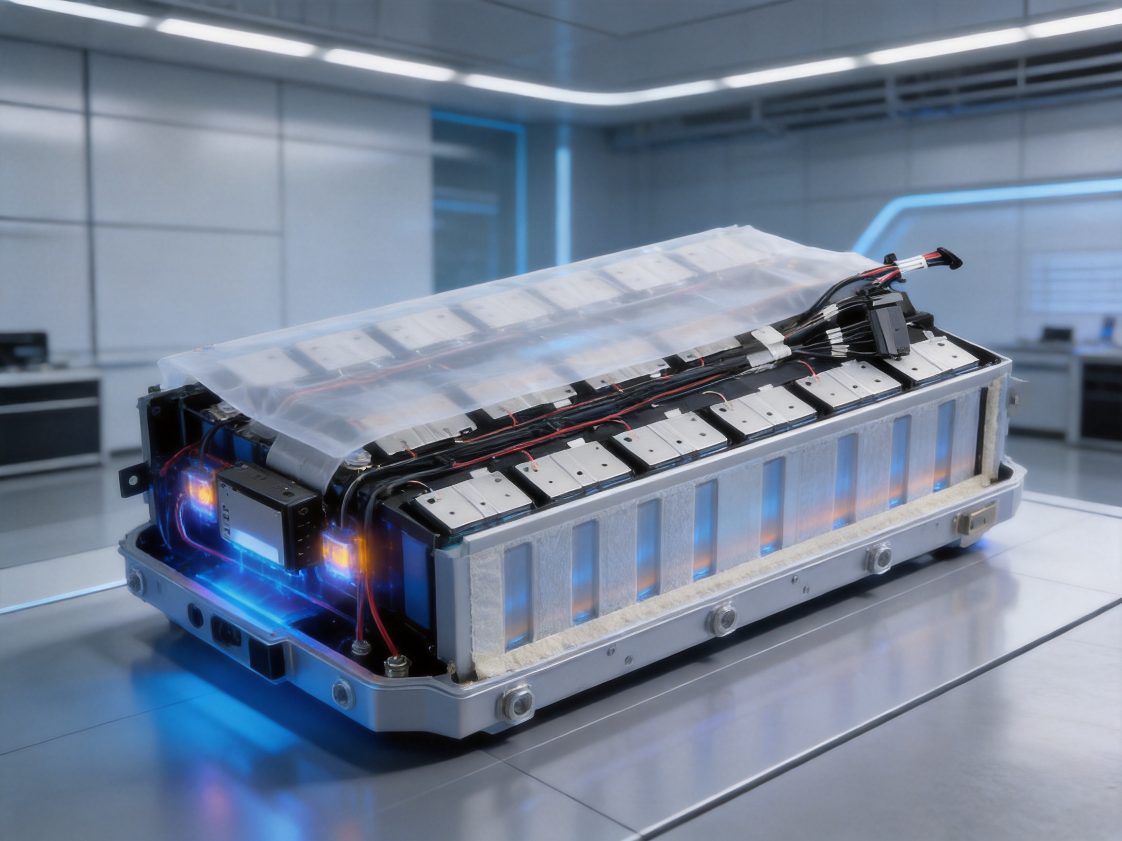
The rapid development of electric vehicles, battery energy storage systems, portable power equipment, and industrial electrification has created a strong demand for compact, reliable, and highly integrated electrical connection systems. Inside a modern battery module, the connection system must perform several functions at the same time. It must connect individual cells electrically, collect voltage information, measure temperature, provide insulation, maintain mechanical stability, and support automated assembly. A conventional collection system may require several separate components and multiple assembly operations. A Cells Contact System, commonly known as a CCS, combines many of these functions into one engineered assembly.
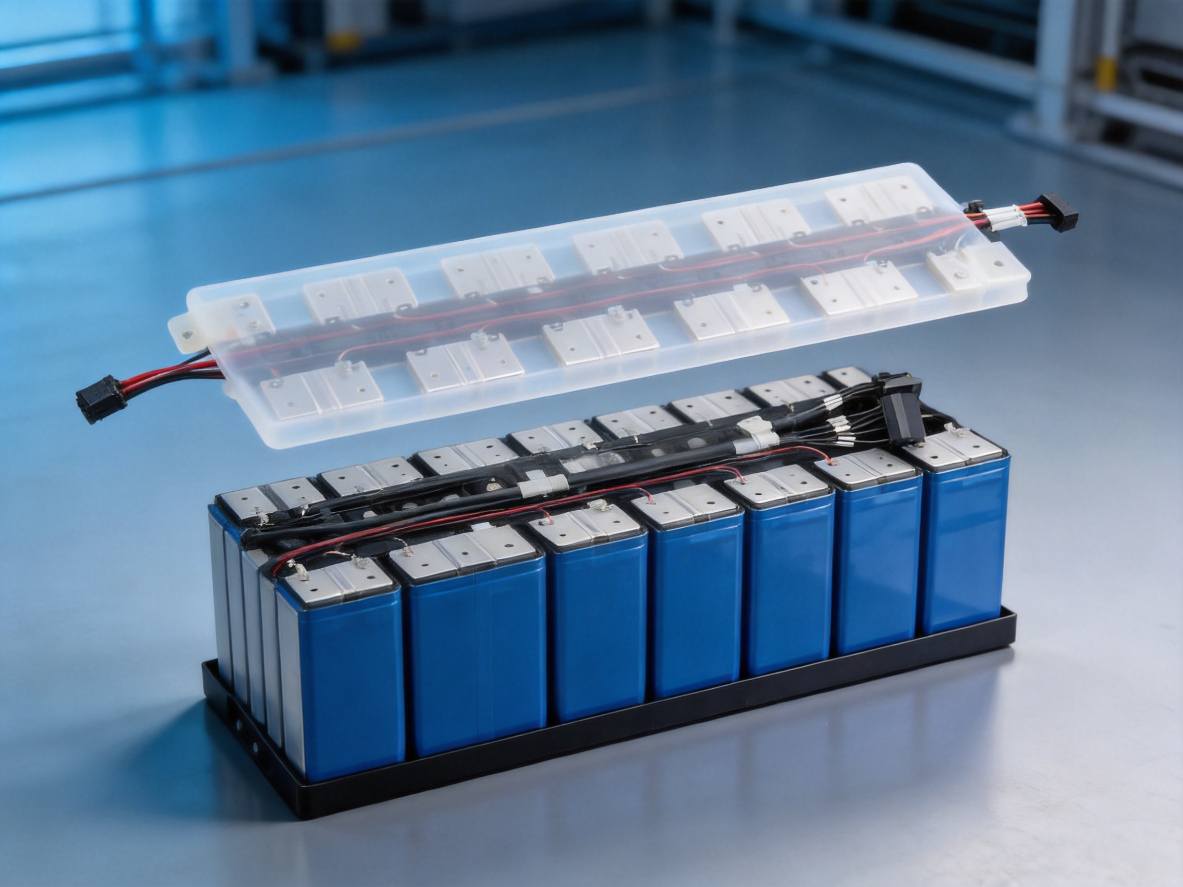
The Wire Harness Type Plastic Cover CCS Integrated Busbar is designed as a multifunctional battery connection and sensing solution. It combines an insulated plastic cover, a flexible wire harness, aluminum busbars, nickel-plated positive and negative terminals, and temperature-sensing components. This structure is intended for energy storage modules and other battery pack applications where electrical performance, sensing accuracy, safety, compactness, and manufacturing efficiency are important.
By integrating current collection and signal transmission into one coordinated product, the assembly can reduce the complexity of battery module construction. It also provides a flexible platform for customized layouts, different cell arrangements, and changing system requirements. Its combination of aluminum busbars, high-temperature XLPE wires, molded or formed insulation components, thermistors, and automated joining processes makes it suitable for demanding applications in new energy transportation and stationary energy storage.
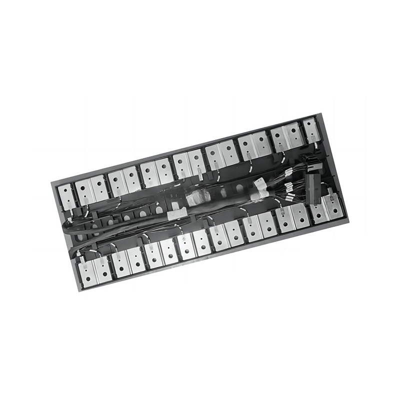
Wire Harness Type Plastic Cover CCS Integrated Busbar
Content
- What Is a Wire Harness Type Plastic Cover CCS?
- Core Product Construction
- Key Technical Specifications
- Advantages Over Conventional Battery Connection Assemblies
- Manufacturing Processes and Quality Strengths
- Engineering Design and Application Analysis
- Material Selection and Incoming Inspection
- Precision Forming of Aluminum Busbars
- Nickel Plating and Surface Preparation
- Wire Cutting, Stripping, and Harness Assembly
- Laser Welding and Automated Joining
- Plastic Molding and Component Integration
- Electrical and Mechanical Testing
- Company Manufacturing and Development Capabilities
- Application Areas
- Design Considerations for OEM Customers
- Installation and Integration Guidance
- Why Custom Manufacturing Matters
- Quality, Reliability, and Validation
- Comparison with Alternative Solutions
- Role in Advanced Energy-Storage Manufacturing
- Purchasing and Project Development Checklist
- Frequently Asked Questions
- What is the primary purpose of this CCS integrated busbar?
- Which materials are used in the product?
- Can the thermistor specification be customized?
- What is the operating temperature range?
- Does the CCS support high-voltage battery modules?
- What flame-retardant performance is specified?
- Why is aluminum used for the busbar?
- What are the benefits of the wire harness structure?
- How is the CCS connected to battery cells?
- Can the product be used in LFP battery systems?
- What testing should be performed before mass production?
- Can the plastic cover be changed for a different module design?
- What should customers provide when requesting a customized solution?
- Conclusion
- References
- Product: Wire Harness Type Plastic Cover CCS Integrated Busbar
What Is a Wire Harness Type Plastic Cover CCS?
A Wire Harness Type Plastic Cover CCS is an integrated cell contact and sensing assembly used in a battery module. The assembly is installed over or alongside a group of battery cells. Its busbars establish electrical connections between selected cell terminals, while its wire harness routes voltage and temperature signals to the battery management system or another monitoring controller.
The plastic cover acts as the structural and insulating foundation of the product. Depending on the required design, it may be produced from PP-GF20, PPO, or PC-ABS. These materials are selected for their combination of mechanical strength, dimensional stability, electrical insulation, heat resistance, and flame-retardant performance. The cover can be designed around the geometry of a particular cell group, allowing the integrated busbar to remain properly positioned during assembly and operation.
The wire harness uses XLPE insulation rated for service temperatures up to 150°C. This gives the signal wiring a substantial thermal margin over the stated operating range of the finished product. The harness can be routed according to the module layout and connected to sensing points without requiring a separate loose-wire installation process.
The current-collection components use AL1060 aluminum. Aluminum is well suited to battery module busbar applications because it is lightweight, has favorable electrical conductivity, dissipates heat efficiently, and can help reduce the total mass of the pack. The positive and negative electrodes can be nickel-plated with a 0.1 mm nickel layer to improve surface compatibility, joining performance, and resistance to environmental influences.
Thermistor components are integrated into the assembly for temperature monitoring. Typical resistance options include 10K3930, 10K3435, and 10K3950, while customized resistance and B-value specifications can also be considered. The stated resistance accuracy is 1 percent, and the B-value accuracy is also 1 percent. These characteristics support accurate temperature estimation when the sensor is properly matched with the battery management system.
Core Product Construction
Plastic Cover and Insulation Structure
The plastic cover is more than a protective shell. It provides a controlled mounting structure for the busbars, wires, and sensing components. A carefully designed cover helps prevent accidental contact between conductive parts and nearby metallic structures. It also contributes to electrical clearance, creepage distance, component positioning, and resistance to vibration.
PP-GF20 is a glass-fiber-reinforced polypropylene option that can provide useful rigidity and dimensional stability while maintaining relatively low weight. PPO can be selected where a higher level of heat resistance and electrical performance is required. PC-ABS can offer a balanced combination of impact resistance, processing flexibility, and appearance. The final material selection should be based on the battery module’s temperature, chemical exposure, flame-retardancy, mechanical, and regulatory requirements.
The insulation plate may also be manufactured from flame-retardant PC-ABS, PA66, or another suitable engineering plastic. The selection of the insulation material allows the CCS design to be adapted to different module structures and operating environments. A properly engineered insulation system protects the busbars and terminals while maintaining a compact overall assembly.
Aluminum Busbar
The busbar is the primary conductive element within the integrated CCS. AL1060 aluminum provides a lightweight conductive path and supports efficient heat dissipation. Compared with a heavier copper structure, an aluminum busbar can contribute to weight reduction, which is especially valuable in electric vehicles and mobile energy systems.
Aluminum also provides design flexibility. It can be formed into straight, stepped, offset, or otherwise customized geometries to follow the arrangement of cylindrical, prismatic, or pouch-cell modules. The low impedance design described for this product supports efficient current collection and helps control electrical losses when the busbar dimensions and connection points are correctly engineered.
Busbar thickness, width, shape, hole pattern, terminal position, and insulation coverage can be customized according to the battery module. This makes the product suitable for application-specific designs rather than a single universal layout. Engineering customization is particularly important because cell spacing, series-parallel configuration, thermal paths, and enclosure dimensions vary significantly between battery systems.
Nickel-Plated Electrodes
The positive and negative aluminum electrodes are nickel-plated with a stated thickness of 0.1 mm. Nickel plating can improve the surface characteristics of the terminal and provide a more suitable interface for joining, welding, or connection to compatible cell components. It may also help address the challenges associated with joining dissimilar conductive materials.
Surface cleanliness is another important requirement. The stated cleanliness target is RFU below 100. In battery manufacturing, contamination control is essential because particles, oils, oxides, and residues can affect welding quality, electrical resistance, insulation performance, and long-term reliability. Maintaining a controlled surface condition supports stable production and reduces the risk of defects during module assembly.
Wire Harness and Signal Routing
The flexible wire harness transmits voltage and temperature signals from the battery cells to the monitoring electronics. XLPE insulation rated at 150°C provides a robust solution for environments that may experience heat generated by charging, discharging, current flow, or nearby components.
A harness-based architecture offers practical advantages over a collection of separately installed wires. Wires can be cut to controlled lengths, routed in predetermined channels, and secured to the cover. This reduces the possibility of incorrect routing, wire entanglement, or accidental interference with cell surfaces and other components. It can also make the battery module easier to assemble and inspect.
The flexible nature of the harness supports design modifications. If the battery cell arrangement or connector location changes, the wire routing and cover geometry can often be revised without redesigning the complete electrical concept. This flexibility is valuable for original equipment manufacturers and battery integrators developing several related module platforms.
Thermistors and Temperature Sensing
Temperature measurement is an essential function in a battery system. A battery management system uses temperature information to monitor cell health, control charging and discharging, detect abnormal conditions, and apply thermal protection strategies. The integrated CCS uses thermistors or equivalent encapsulated resistance components to provide this information.
Typical thermistor options include 10K3930, 10K3435, and 10K3950. The first number generally identifies the nominal resistance at 25°C, while the second number represents the B-value, which describes the resistance-temperature relationship. The use of a specified and controlled resistance curve allows the battery management system to interpret sensor output accurately.
The stated R25 resistance accuracy is 1 percent, and the B-value accuracy is also 1 percent. These specifications can support high sensitivity and rapid response. However, the final temperature accuracy of a complete battery system also depends on sensor placement, thermal contact, wiring resistance, signal-conditioning electronics, calibration, and the software model used by the battery management system.
Key Technical Specifications
| Item | Stated Specification | Application Significance |
|---|---|---|
| Plastic cover materials | PP-GF20, PPO, or PC-ABS | Provides insulation, structural support, and customized module integration |
| Wire harness insulation | XLPE, rated to 150°C | Supports reliable signal routing in elevated-temperature environments |
| Busbar material | AL1060-O | Offers low weight, favorable conductivity, and efficient heat dissipation |
| Electrode surface | Positive and negative electrodes nickel-plated, 0.1 mm | Improves terminal surface suitability for joining and connection |
| Thermistor options | 10K3930, 10K3435, 10K3950, or customized types | Supports cell temperature monitoring and system-specific calibration |
| Resistance accuracy | R25°C 1%; B-value 1% | Enables consistent temperature-sensing performance |
| Operating temperature | -40°C to 125°C | Supports a broad range of vehicle and energy-storage environments |
| Withstand voltage | 3000 V AC for 60 seconds; leakage current below 1 mA | Supports dielectric-strength verification of the assembly |
| Insulation resistance | More than 500 megohms at 1000 VDC | Helps confirm strong electrical separation |
| Flame-retardant rating | Meets UL94 V-0 | Supports fire-safety objectives for insulated components |
| Output signal | Analog signal output | Allows integration with battery monitoring electronics |
| Finished-product voltage statement | Up to 4200 VDC, subject to design verification | Indicates suitability for high-voltage module architectures when validated |
The specifications in this table describe the supplied product information. Actual performance depends on the final design, materials, dimensions, assembly method, testing conditions, and customer requirements. High-voltage systems should always be evaluated through a complete validation program rather than by relying on a component rating alone.
Advantages Over Conventional Battery Connection Assemblies
Higher Functional Integration
A conventional battery module may use separate busbars, loose voltage-sensing wires, independent temperature sensors, individual insulation parts, and manually installed fasteners. Each additional part increases the number of assembly steps and creates more opportunities for installation errors. A CCS integrates many of these functions into one coordinated assembly.
The integrated structure can simplify logistics, reduce the number of loose components, and make assembly instructions easier to standardize. It can also provide a cleaner internal module layout. For high-volume battery manufacturing, this type of integration may improve line efficiency and support more consistent product quality.
Reduced Weight
AL1060 aluminum busbars help reduce the mass of the electrical connection system. Weight reduction is valuable in electric vehicles because lower mass can contribute to improved driving range, acceleration, and energy efficiency. In stationary storage systems, lower weight can simplify transportation, cabinet installation, and maintenance handling.
The weight advantage does not mean that the busbar can be made arbitrarily thin. Current capacity, temperature rise, mechanical strength, connection resistance, and short-circuit requirements must all be considered. The benefit comes from selecting an aluminum structure that is appropriately engineered for the required current and thermal conditions.
Flexible Design Modification
The wire harness architecture supports variations in cell arrangement, sensing location, connector direction, and module geometry. This is a major advantage over rigid, fixed-layout systems that require extensive rework when a battery platform changes.
Customization may include busbar shape, terminal spacing, sensor quantity, wire length, connector type, insulation material, mounting features, and output configuration. The ability to revise these details gives battery manufacturers more freedom during product development and helps shorten the transition from prototype to production.
Improved Signal Management
Stable signal transmission is essential for accurate monitoring. A designed wire harness keeps sensing wires organized and reduces the chance of accidental damage during module assembly. The harness can be routed through defined paths and supported by the plastic cover, improving repeatability from one module to another.
Analog temperature and voltage signals must be protected from noise, mechanical stress, and unintended contact with power conductors. The exact signal-integrity result depends on harness routing and the battery management system, but a purpose-built CCS provides a better starting point than a collection of unstructured wires.
Reliable Temperature Monitoring
The integration of thermistors into the CCS places sensing components close to the cell connection area. This can provide timely feedback about temperature changes. Fast response is valuable when the battery is charged or discharged at high current, when thermal gradients develop within a module, or when an abnormal cell condition must be detected quickly.
The product information indicates high sensitivity and resistance and B-value accuracy of up to ±1 percent. Such consistency can reduce variation between sensor channels and simplify calibration. The sensing design should nevertheless be validated under actual operating conditions, including low-temperature operation, high-temperature storage, rapid charging, vibration, and repeated thermal cycling.
Strong Insulation and Fire Resistance
The plastic cover and insulation plate provide physical separation around conductive components. The stated insulation resistance is greater than 500 megohms when tested at 1000 VDC. The stated dielectric test is 3000 V AC for 60 seconds with leakage current below 1 mA. The materials are also described as meeting UL94 V-0 flame-retardant requirements.
These characteristics support the safety design of a battery module. They can help reduce the risk of unintended current paths, flashover, and ignition propagation. Electrical insulation performance must be assessed together with creepage distance, clearance, contamination level, humidity, mechanical deformation, and the complete battery enclosure design.
Efficient Heat Dissipation
Aluminum offers good thermal conductivity and can help transfer heat away from connection areas. The busbar’s low impedance also helps reduce resistive heat generation when the conductor is correctly sized and the joints are properly formed. Efficient heat management supports long-term stability and helps protect the cells and adjacent components.
The overall thermal performance of a battery module depends on many additional factors, including cell chemistry, current profile, cooling plates, thermal interface materials, module compression, enclosure ventilation, and ambient conditions. The CCS contributes to the electrical and local thermal design but should not be viewed as a replacement for a complete battery thermal-management system.
Manufacturing Processes and Quality Strengths
Engineering Design and Application Analysis
The manufacturing process begins with a clear understanding of the battery module. Engineers evaluate cell type, cell pitch, series-parallel configuration, current level, sensing points, available installation space, connector direction, and insulation requirements. They also review mechanical tolerances and the expected environmental conditions.
Computer-aided design can be used to define the busbar profile, wire paths, cover geometry, mounting features, and terminal positions. The design process should include checks for electrical clearance, assembly accessibility, bend radii, heat paths, and possible interference with cell housings or cooling structures.
Because the product is intended for customized battery integration, the engineering process is an important competitive advantage. A manufacturer that can connect design, tooling, material selection, welding, testing, and production support in one workflow can help customers reduce development complexity.
Material Selection and Incoming Inspection
Reliable CCS performance depends on controlled raw materials. Aluminum sheet or strip must meet the required alloy, temper, thickness, surface condition, and dimensional tolerances. Nickel-plating materials and processes must be controlled to achieve the specified layer thickness and surface quality. Plastic materials must be checked for grade, color, flame-retardant characteristics, and processing suitability.
XLPE wire should be verified for conductor size, insulation thickness, temperature rating, voltage rating, flexibility, and traceability. Thermistors should be inspected for nominal resistance, B-value, tolerance, encapsulation quality, and response consistency. Incoming inspection reduces the likelihood that material variation will affect downstream assembly.
Precision Forming of Aluminum Busbars
Aluminum busbars may be cut, stamped, bent, punched, or formed according to the product design. Precision forming is needed to maintain terminal position and ensure that the finished assembly fits the battery module without excessive force. Burrs and sharp edges must be controlled because they can damage insulation or create local electric-field concentrations.
The busbar’s surface should be cleaned and protected as required before plating or joining. Dimensional inspection can verify length, width, thickness, hole location, bend angle, flatness, and terminal alignment. Automated or semi-automated equipment may be used to improve repeatability and production speed.
Nickel Plating and Surface Preparation
Nickel plating is applied to the specified positive and negative electrode areas. The plating process must provide consistent coverage, adhesion, thickness, and cleanliness. Surface preparation before plating is critical because oils, oxides, and particles may reduce adhesion or affect the quality of subsequent joining operations.
After plating, the parts can be inspected through visual examination, thickness measurement, adhesion verification, and cleanliness testing. The stated RFU below 100 cleanliness target reflects the importance of controlling residues on battery connection parts. Production records can be maintained to support traceability and continuous improvement.
Wire Cutting, Stripping, and Harness Assembly
The XLPE wire harness is produced according to the approved drawing and electrical schematic. Wire lengths must be controlled carefully because excess length can create loops and interference, while insufficient length can apply stress to terminals or connectors. Stripping operations must expose the correct conductor length without nicking or weakening the conductor.
Terminals, connectors, sensor leads, and protective features are assembled using controlled processes. Crimp height, pull-out force, insertion force, continuity, and polarity can be inspected according to the relevant customer specification. Proper strain relief is important because vibration and thermal movement can otherwise transfer stress to the sensing components.
Laser Welding and Automated Joining
The product information identifies laser welding as a connection and fixing method. Laser welding can provide precise, repeatable, and clean joints when the materials, energy input, focus, speed, and clamping conditions are properly controlled. It is suitable for automated manufacturing and can help create strong, visually consistent connections.
Compared with a highly manual joining process, automated laser welding can improve positional accuracy and reduce variation between production batches. The process can also be monitored through equipment parameters and inspection systems. Weld quality may be evaluated using visual inspection, electrical resistance measurement, pull testing, cross-sectional analysis, or other methods defined by the production-control plan.
Polymer diffusion welding and other advanced joining technologies may also be used within a manufacturer’s wider precision-component capability. These processes can support low-resistance, high-reliability electrical connections when applied to suitable material combinations and validated through appropriate testing.
Plastic Molding and Component Integration
The plastic cover and insulation plate can be produced through injection molding or another controlled polymer-forming process. Tooling must account for shrinkage, warpage, wall thickness, fastening points, clips, wire channels, and cell-module tolerances. Proper mold design helps achieve stable dimensions and a smooth surface that will not damage wires or cell insulation.
After molding, the cover can be combined with the busbar, harness, sensors, and terminals. Assembly fixtures help maintain component location while the parts are joined or secured. A fixture-based process improves repeatability and reduces the risk of incorrectly positioned sensors or misaligned terminals.
Electrical and Mechanical Testing
Each finished CCS can be subjected to inspection and testing appropriate to its application. Electrical tests may include continuity, resistance, polarity, insulation resistance, and dielectric withstand. The stated withstand test is 3000 V AC for 60 seconds with leakage current below 1 mA, while the stated insulation resistance exceeds 500 megohms at 1000 VDC.
Thermistor checks may confirm nominal resistance, resistance-temperature behavior, B-value consistency, and channel identification. Mechanical tests may include terminal pull force, wire retention, connector engagement, dimensional inspection, and vibration-related assessment. The finished assembly may also be checked for visual defects, contamination, cracks, incomplete welds, loose components, or damaged insulation.
When the design is intended for higher-voltage applications, the stated finished-product withstand capability of up to 4200 VDC should be validated under the exact customer design and test conditions. Voltage rating can be affected by spacing, material selection, humidity, contamination, geometry, and test method. A responsible qualification program therefore evaluates the complete assembly, not only individual components.
Company Manufacturing and Development Capabilities
Zhejiang Zhongyan New Energy Co., Ltd. is a high-tech enterprise focused on new energy conductive components and precision electrical connection products. Its product scope includes high-voltage electrical copper foil soft connections, special-shaped soft connections, battery soft connections, and related components for power transmission, electric vehicles, rail transit, communications, and energy storage.
The company brings together engineering personnel, technical teams, production equipment, and quality-management resources for the development and manufacture of soft connection products. This combination is significant for CCS production because the product requires coordination between conductive materials, polymer insulation, precision forming, sensing technology, welding, testing, and battery-module integration.
Established in 2022, the company has developed capabilities in new energy precision components, including battery soft connections. Its independently developed polymer diffusion welding and laser technology patents are intended to support electrical connections with low internal resistance and high reliability. These capabilities can strengthen the production of customized busbars and other battery connection components.
The company states that it supplies leading enterprises including BYD, CATL, and Jaguar. Such stated customer relationships indicate experience with demanding requirements, although each project’s quality level, qualification status, and delivery performance should be evaluated according to the specific purchasing and audit process of the customer.
The company is also developing a broader research and development system covering materials science, precision machining, testing, and verification. This integrated approach is useful for CCS projects because successful battery integration often requires more than manufacturing a drawing. It may require material recommendations, process adjustments, prototype development, sample testing, design-for-manufacturing reviews, and production ramp-up assistance.
Application Areas
Electric Vehicles
Electric vehicle battery packs require compact, lightweight, and dependable electrical connection systems. The integrated CCS can connect battery cells and transmit voltage and temperature information to the battery management system. Its aluminum structure can help limit pack weight, while the insulated cover supports safe integration into a high-voltage battery enclosure.
Vehicle applications also expose components to vibration, thermal cycling, humidity, rapid charging, and long service periods. For this reason, the final CCS must undergo qualification testing that reflects the vehicle platform, cell chemistry, module design, and environmental requirements.
Battery Energy Storage Systems
Stationary energy storage modules used for renewable-energy integration, peak shaving, backup power, and industrial power management require reliable cell monitoring and current collection. A CCS can support modular battery architecture while helping manufacturers standardize the internal connection system.
Energy storage installations may operate in warehouses, outdoor cabinets, containerized systems, or utility sites. The appropriate insulation, flame-retardant, moisture-resistance, and temperature requirements vary by installation. A customized plastic cover and harness layout can help adapt the CCS to different module formats.
Industrial and Portable Power Equipment
Battery-powered tools, robotics, material-handling equipment, portable power stations, and specialized industrial machines can benefit from integrated busbar and sensing assemblies. These applications often value compact design, easy assembly, and reliable temperature feedback.
The flexible harness can be adapted to different connector positions and cell arrangements. The product may also support battery modules that require a balance between high current capability, low weight, and efficient production.
Design Considerations for OEM Customers
Cell Chemistry and Cell Format
The CCS should be matched to the cell chemistry and format. Lithium iron phosphate batteries, nickel-manganese-cobalt batteries, and other lithium-ion chemistries may have different voltage, thermal, and safety characteristics. Cylindrical, prismatic, and pouch cells also require different terminal layouts and mechanical support structures.
For LFP battery systems, the integrated busbar must be designed around the selected cell dimensions, connection method, maximum current, balancing architecture, and battery management system. A product that is appropriate for one cell format may not be suitable for another without modifications.
Current, Voltage, and Thermal Requirements
Busbar dimensions should be selected according to continuous current, peak current, allowable temperature rise, short-circuit conditions, and cooling design. The electrical resistance of joints and terminals must also be included in the thermal analysis. A low-resistance busbar is beneficial, but the complete current path must be analyzed.
For high-voltage modules, insulation spacing and dielectric performance are equally important. The designer should evaluate working voltage, transient voltage, test voltage, pollution level, altitude, humidity, and enclosure conditions. The stated 3000 V AC test and up to 4200 VDC finished-product statement provide reference points, but the final design must be qualified for its intended system.
Connector and Interface Definition
The output connector must match the battery management system and module communication architecture. Pin assignment, wire color, wire gauge, connector locking, keying, sealing, and serviceability should be defined before tooling is finalized. Correct polarity and channel identification are essential for safe commissioning.
Customers should provide interface drawings, cell maps, electrical schematics, and installation requirements during the design phase. Early information exchange helps prevent changes after tooling and reduces the risk of mismatches during prototype assembly.
Environmental Protection
The product advantages include waterproof and moisture-proof temperature measurement performance. The actual protection level depends on the encapsulation, cover design, connector sealing, wire routing, and module enclosure. Environmental testing should include humidity, condensation, thermal shock, salt exposure where applicable, vibration, and chemical compatibility.
Battery modules can contain electrolytes, adhesives, coolants, cleaning agents, and other substances. The plastic and wire materials should be evaluated for compatibility with substances that may be present during manufacture or operation.
Installation and Integration Guidance
Before installation, the battery module and CCS should be checked for contamination, deformation, damaged insulation, loose components, and incorrect part numbers. The cell arrangement should correspond to the approved assembly drawing. The installer should avoid bending busbars or wires beyond their designed range.
Terminals should be aligned with the cell connection points before welding or fastening. Excessive force can damage cell terminals, deform the busbar, or alter the position of the thermistor. If laser welding is used, the welding parameters should be controlled according to the approved process window.
After installation, electrical continuity, polarity, insulation resistance, and sensor resistance should be checked. Temperature sensors should be verified through a controlled temperature comparison or another approved calibration method. The module should not be energized until all high-voltage and insulation checks have passed.
Service personnel should follow appropriate high-voltage battery safety procedures. The CCS is an integrated component, but it does not eliminate the need for system-level protection such as fuses, contactors, isolation monitoring, pre-charge circuits, current sensors, and protective enclosures.
Why Custom Manufacturing Matters
Battery modules are rarely identical across industries. Even two products using the same nominal cell type may differ in cell spacing, current demand, cooling arrangement, connector location, and enclosure structure. A custom CCS therefore provides greater value than an off-the-shelf component that only partially matches the module.
Custom manufacturing allows the busbar to follow the shortest practical current path, the harness to reach the correct sensing points, and the insulation cover to fit the available space. It also allows the customer to select materials and thermistor characteristics that match the environmental and control requirements.
Customization should be managed through a documented engineering process. This normally includes drawing review, electrical schematic confirmation, prototype sampling, dimensional approval, process validation, reliability testing, and production release. Clear revision control prevents an outdated design from entering production.

Quality, Reliability, and Validation
Reliability is created through the combination of design, material control, process control, inspection, and application testing. A CCS should be considered a safety-related battery component because an electrical connection failure or insulation defect can affect the operation of the entire module.
Recommended validation activities may include thermal cycling from low to high temperature, high-temperature aging, humidity exposure, vibration, mechanical shock, current-carrying tests, dielectric withstand, insulation resistance, connector durability, wire pull testing, weld strength evaluation, and contamination assessment.
Temperature sensors should be evaluated for response time, resistance stability, drift, encapsulation integrity, and performance after thermal cycling. Busbars should be assessed for resistance growth, joint integrity, deformation, and corrosion. Plastic covers should be checked for cracking, warpage, flame behavior, and retention after environmental exposure.
Production quality records should connect the final part to the relevant material batch, tooling condition, welding parameters, inspection results, and operator or equipment information. Traceability is particularly useful when customers operate large battery production lines and need to investigate field or process issues.
Statistical process control can be applied to important characteristics such as busbar dimensions, plating thickness, wire length, crimp height, sensor resistance, insulation resistance, and weld resistance. Monitoring these characteristics helps identify process drift before it creates a large number of nonconforming assemblies.
Comparison with Alternative Solutions
Loose-wire battery sensing systems may have a lower initial tooling requirement, but they often require more manual routing and fastening. They can be difficult to organize in compact modules and may have greater variation between assemblies. A wire harness type CCS provides a defined structure and a more repeatable installation method.
Rigid copper busbar systems can provide high conductivity, but they may increase weight and require additional insulation or support parts. The AL1060 busbar approach can reduce mass and improve heat dissipation while retaining the ability to customize the conductor geometry.
Separate temperature-sensor assemblies can provide flexibility, but they add components and installation operations. Integrating thermistors into the CCS can reduce the number of individual parts and place sensors in controlled locations.
Purely rigid collection plates may be less adaptable when the battery layout changes. The flexible wire harness and customizable plastic cover provide greater design freedom for revised cell spacing, output interfaces, and module structures.
These comparisons do not mean that one architecture is suitable for every battery. The right solution depends on current, voltage, cell format, production volume, service requirements, and qualification standards. The main advantage of the Wire Harness Type Plastic Cover CCS is the coordinated integration of several functions into a single customizable assembly.
Role in Advanced Energy-Storage Manufacturing
The battery industry is moving toward higher energy density, faster production, stronger traceability, and more automated assembly. These trends favor components that are designed for manufacturing rather than assembled manually from many independent parts.
A CCS can support automation through controlled component positioning, laser welding, harness routing, connector installation, and electrical testing. Automated processes can improve repeatability and reduce the effect of operator variation. They can also provide production data that supports quality analysis and customer audits.
The company’s focus on new energy conductive components, precision machining, polymer diffusion welding, laser technology, and integrated battery connection systems aligns with these manufacturing trends. Its development direction includes the integration of battery cells and connection systems, which may enable more coordinated optimization of electrical, mechanical, thermal, and sensing functions.
For customers, this means that supplier capability should be evaluated not only by the appearance of a sample. Important questions include whether the supplier can control material quality, manage tooling, validate welding, maintain cleanliness, provide inspection data, support engineering changes, and deliver consistent production quantities.
Purchasing and Project Development Checklist
When requesting a quotation for a customized CCS, the customer should provide the cell drawing, module layout, electrical schematic, maximum current, operating voltage, temperature range, connector requirements, sensing points, installation method, and applicable standards.
The supplier should clarify the proposed busbar alloy and temper, busbar thickness, nickel-plating thickness, plastic material, wire specification, thermistor curve, connector model, welding method, insulation requirements, and inspection plan. The quotation should identify which specifications are standard and which require customization.
Prototype quantities should be used to confirm fit, connector orientation, wire routing, sensor position, terminal alignment, weld appearance, and electrical performance. Design changes are generally easier and less costly during the prototype stage than after mass-production tooling has been approved.
Before production release, both parties should approve the final drawing, bill of materials, control plan, test requirements, packaging method, labeling, and change-control procedure. This documentation creates a clear technical basis for consistent supply.
Frequently Asked Questions
What is the primary purpose of this CCS integrated busbar?
Its primary purpose is to connect battery cells electrically while simultaneously routing voltage and temperature signals to the battery management system. The plastic cover provides insulation and structural support, creating a more integrated alternative to separate busbars, wires, sensors, and insulation components.
Which materials are used in the product?
The plastic cover may use PP-GF20, PPO, or PC-ABS. The wire harness uses XLPE insulation rated to 150°C. The busbar uses AL1060 aluminum, and the positive and negative electrodes are nickel-plated with a stated thickness of 0.1 mm. Thermistor components are encapsulated resistance sensors with customizable specifications.
Can the thermistor specification be customized?
Yes. Typical options include 10K3930, 10K3435, and 10K3950. Resistance accuracy and B-value accuracy are stated at 1 percent, and customized resistance and B-value requirements can be discussed according to the battery management system and application.
What is the operating temperature range?
The stated operating temperature range is -40°C to 125°C. The wire insulation is rated to 150°C, providing an additional material rating margin. Final application suitability should be confirmed through testing under the customer’s actual thermal conditions.
Does the CCS support high-voltage battery modules?
The product information states a 3000 V AC withstand test for 60 seconds and a finished-product voltage capability of up to 4200 VDC. These figures should be treated as design and test references. The actual working-voltage suitability must be confirmed for the complete customized assembly and its intended battery system.
What flame-retardant performance is specified?
The plastic material is stated to meet the UL94 V-0 flame-retardant rating. The exact rating must be verified for the selected material grade, thickness, molded part, and applicable certification requirements.
Why is aluminum used for the busbar?
AL1060 aluminum offers a favorable combination of low weight, electrical conductivity, and heat dissipation. It can reduce the mass of the battery connection system compared with heavier alternatives. The busbar must still be sized and validated for the required current, temperature rise, mechanical strength, and short-circuit conditions.
What are the benefits of the wire harness structure?
The wire harness organizes voltage and temperature signal paths, supports stable transmission, reduces loose-wire assembly, and allows the layout to be modified for different battery modules. It can also improve installation repeatability when used with a properly designed plastic cover.
How is the CCS connected to battery cells?
The connection method depends on the cell design and customer requirements. The product information identifies laser welding as a connection and fixing method. The approved welding process must be developed and validated for the selected cell terminal, busbar, plating, and production equipment.
Can the product be used in LFP battery systems?
It can be considered for LFP battery modules when the busbar layout, voltage, current, sensing requirements, insulation, and mechanical design are properly matched. The final product must be customized and validated for the selected LFP cell format and battery management system.
What testing should be performed before mass production?
Recommended testing includes dimensional inspection, continuity, polarity, resistance, thermistor verification, insulation resistance, dielectric withstand, weld strength, wire retention, thermal cycling, humidity, vibration, and current-carrying evaluation. The exact test plan should reflect the customer’s standards and application.
Can the plastic cover be changed for a different module design?
Yes. The cover can be redesigned to match different cell spacing, terminal positions, mounting points, wire routes, connectors, and insulation requirements. The redesign should be controlled through approved drawings and prototype verification.
What should customers provide when requesting a customized solution?
Customers should provide cell drawings, module dimensions, electrical schematics, current and voltage requirements, temperature-sensing points, connector details, environmental conditions, applicable standards, and expected production quantities. Complete information helps the manufacturer develop a practical and cost-effective design.
Conclusion
The Wire Harness Type Plastic Cover CCS Integrated Busbar is a multifunctional solution for modern battery modules. It combines aluminum current collection, insulated structural support, flexible signal wiring, and accurate temperature sensing in one coordinated assembly. Its principal advantages include reduced component count, lower weight, flexible customization, organized signal transmission, efficient heat dissipation, strong insulation, and compatibility with automated manufacturing.
The product is particularly suitable for electric vehicles, energy storage systems, LFP battery modules, industrial equipment, and other applications that require reliable cell connection and monitoring. The use of AL1060 aluminum, nickel-plated electrodes, XLPE wire, engineering-plastic covers, and thermistors provides a foundation for high-performance battery integration.
Zhejiang Zhongyan New Energy Co., Ltd. contributes capabilities in new energy conductive components, battery soft connections, precision manufacturing, laser welding, polymer diffusion welding, materials engineering, and testing. Its integrated development approach can support customers from initial design and prototype production through validation and mass manufacturing.
As battery systems become more compact, powerful, and automated, integrated connection systems will become increasingly important. A well-designed CCS is not simply a busbar with wires attached. It is an engineered interface between the cells, the battery management system, the mechanical module, and the safety architecture. When its materials, structure, manufacturing processes, and testing requirements are matched carefully to the application, it can help battery manufacturers achieve safer, more consistent, and more efficient production.
References
1. Product technical information for Wire Harness Type Plastic Cover CCS Integrated Busbar, including material, electrical, thermal, insulation, and sensing specifications.
2. General engineering principles for lithium-ion battery module design, cell interconnection, voltage monitoring, and temperature measurement.
3. UL 94, Standard for Tests for Flammability of Plastic Materials for Parts in Devices and Appliances.
4. General practices for dielectric withstand testing and insulation-resistance measurement in high-voltage electrical assemblies.
5. Engineering references for aluminum busbar design, electrical resistance, current capacity, thermal management, and mechanical joining.
6. Manufacturing quality-control principles for laser welding, polymer joining, wire-harness assembly, material traceability, and production validation.
7. Battery-management-system design guidance for thermistor resistance curves, B-value accuracy, temperature calibration, and analog signal integration.
Product: Wire Harness Type Plastic Cover CCS Integrated Busbar

Driven by the development of new energy and aiming for "zero carbon".
Copyright © Zhejiang Zhongyan New Energy Co., Ltd. All Rights Reserved.
