Laminated Busbars: High-Frequency Performance, Flex Life, and Power Module Integration
Why Are Laminated Busbars Better Suited for High-Frequency Applications Than Standard Copper Busbars?
The high-frequency advantage of laminated busbars
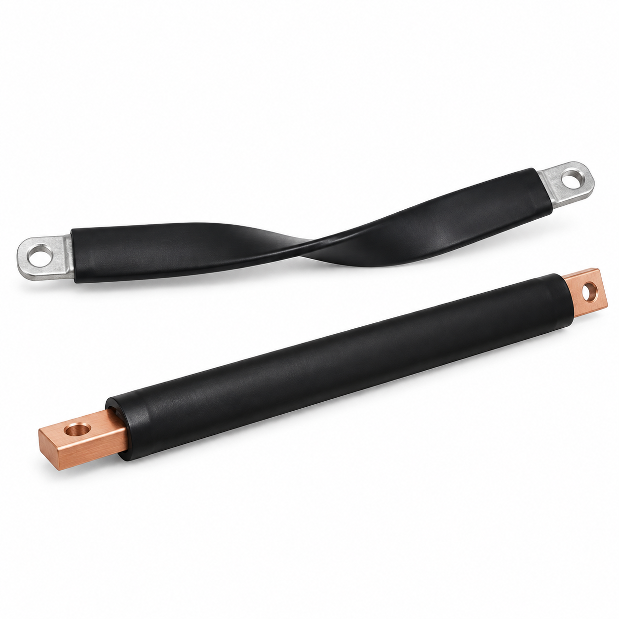
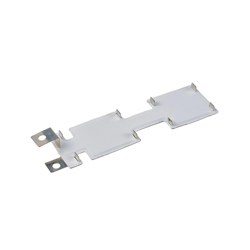
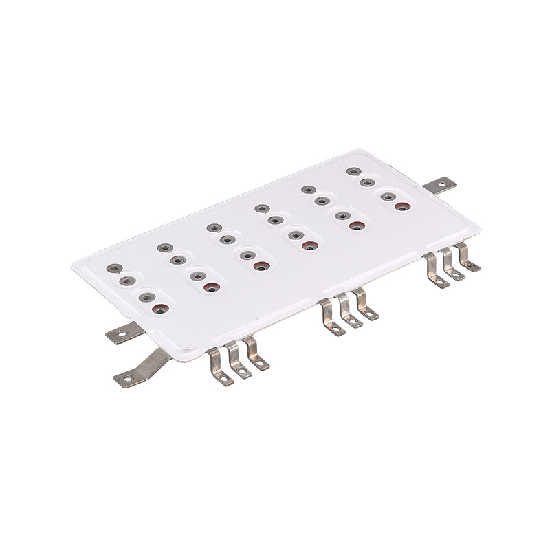
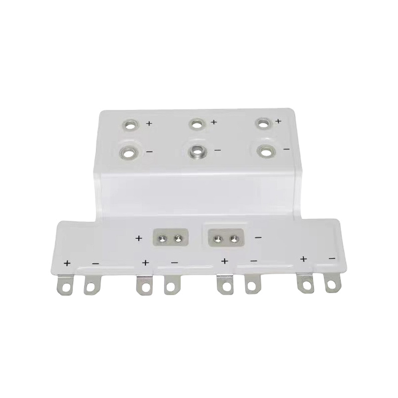
Laminated busbars are constructed from multiple thin layers of copper separated by a thin dielectric insulation. This laminated structure provides superior performance in high-frequency applications compared to standard copper busbars. The advantages are rooted in the reduction of skin effect and proximity effect losses, and the control of parasitic inductance and capacitance.
The skin effect in high-frequency applications
At high frequencies, current tends to concentrate on the surface of a conductor—this is the skin effect. In a solid copper busbar, the skin effect increases the effective resistance, reducing the current-carrying capacity and generating more heat. The laminated busbar, with its multiple thin conductors, provides multiple parallel paths for current flow. The skin effect is less pronounced in the thin layers, resulting in lower AC resistance and more effective use of the conductor material. This is a significant advantage in high-frequency applications such as power converters and inverters.
The proximity effect
The proximity effect causes current to concentrate in regions of the conductor that are closest to the return path, creating additional losses. The laminated busbar's layered construction reduces the proximity effect by providing a uniform field distribution and minimizing the distance between the forward and return current paths.
The parasitic inductance and capacitance
The layered construction also reduces parasitic inductance and provides controlled capacitance. The tight coupling between the layers lowers the inductance, which is essential for reducing voltage overshoot and electromagnetic interference in high-frequency circuits. The controlled capacitance can be used to filter noise and reduce the size of external filtering components.
The Difference of laminated and solid copper busbars for high-frequency applications
- Laminated busbars: reduced skin effect, lower proximity effect, lower parasitic inductance, controlled capacitance, lower AC resistance, suitable for high-frequency
- Solid copper busbars: significant skin effect, higher proximity effect, higher parasitic inductance, uncontrolled capacitance, higher AC resistance, not suitable for high-frequency
The bending cycle life of laminated flexible busbars
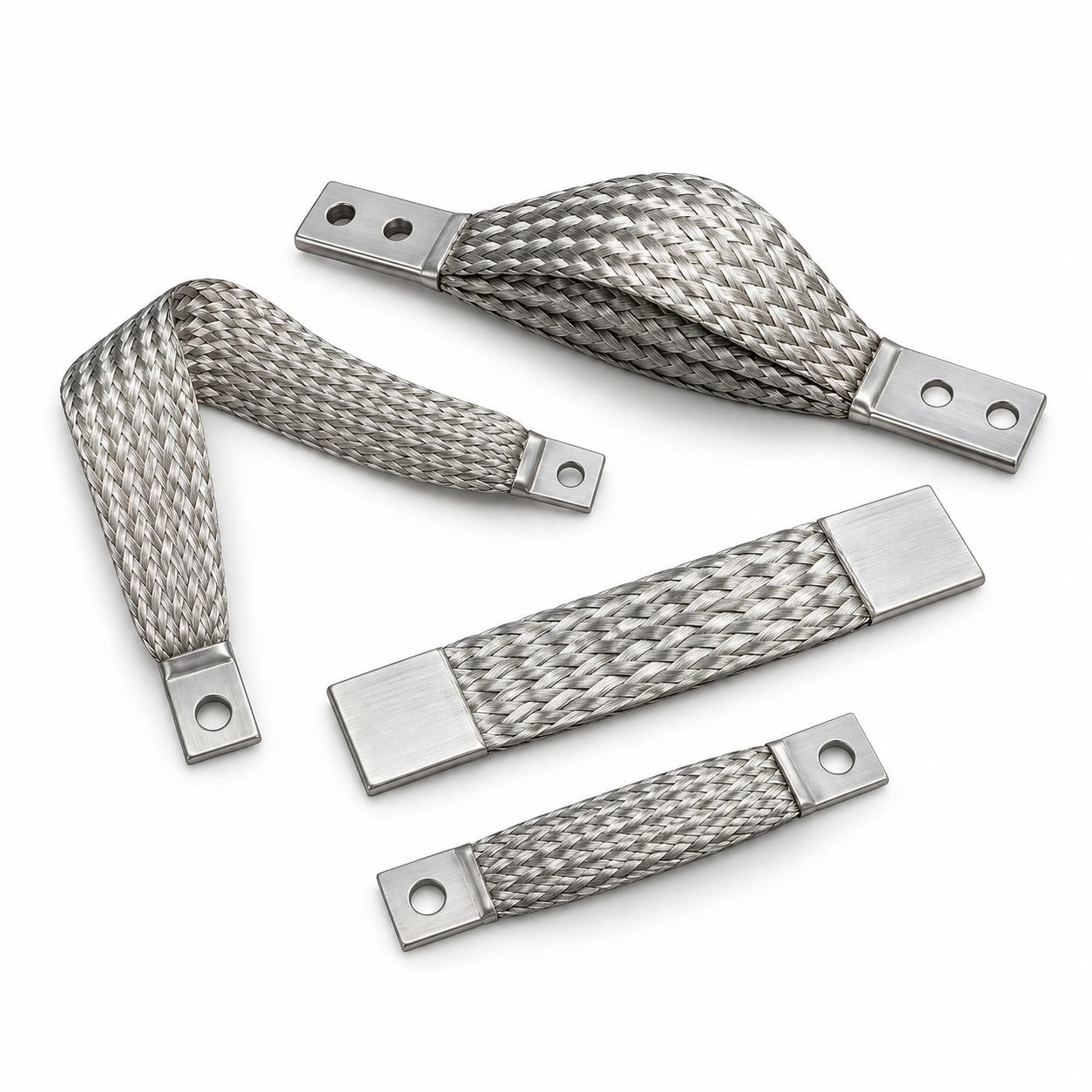
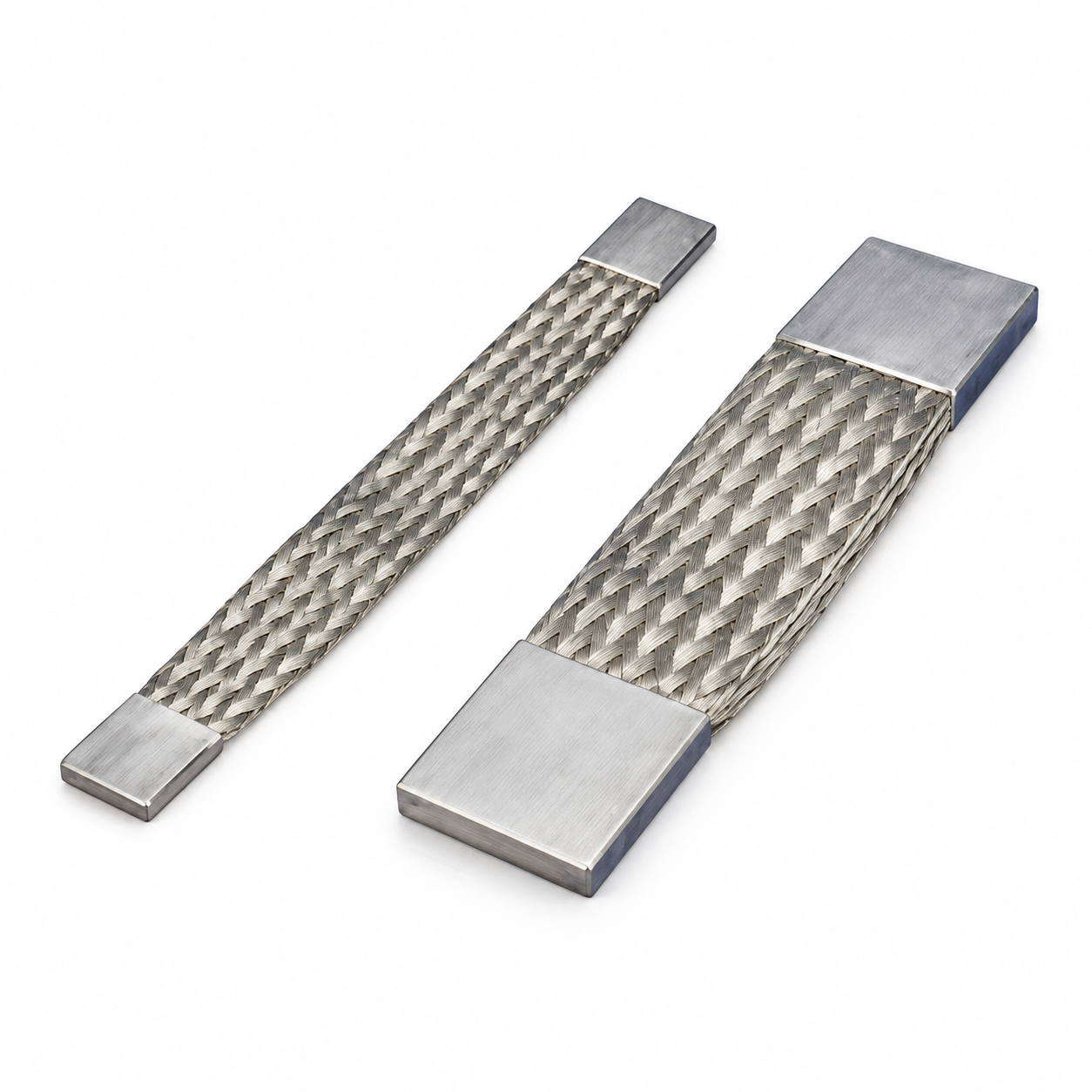
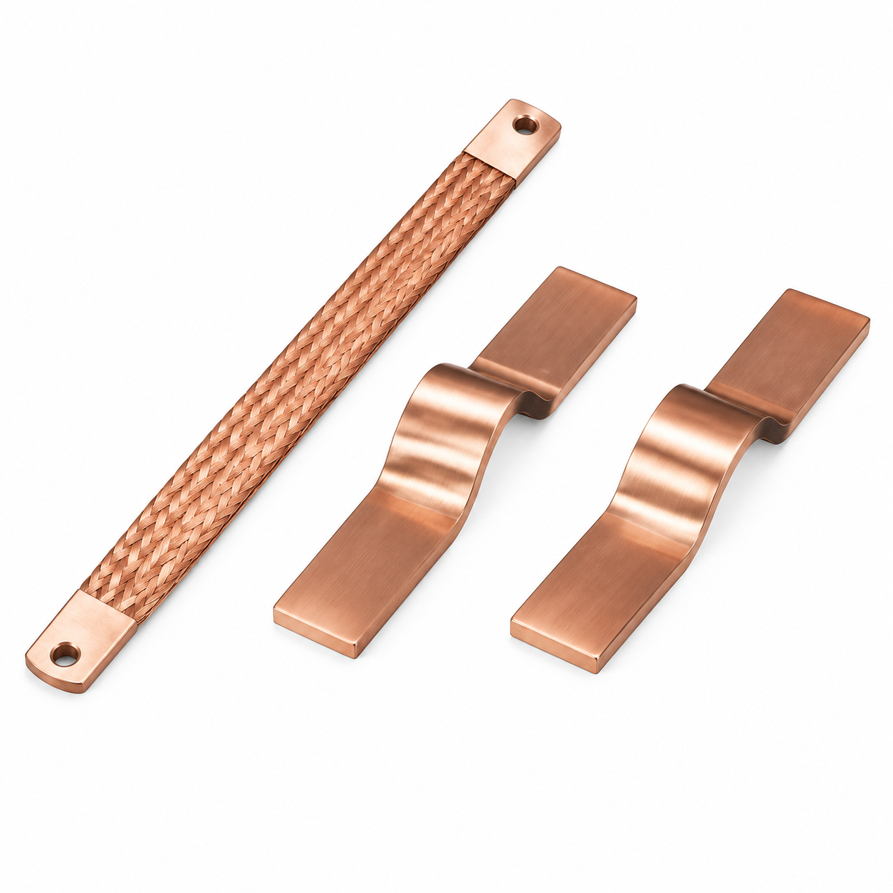
Laminated flexible busbars are designed to withstand repeated bending in applications where movement, vibration, or thermal expansion must be accommodated. How many bending cycles a laminated flexible busbar can withstand depends on the material, the construction, and the bending conditions.
The factors affecting bending cycle life
The bending cycle life is primarily determined by the thickness of the individual copper layers and the bending radius. Thinner layers—typically 0.1–0.3 mm—can withstand more bending cycles before fatigue failure occurs. The bending radius is a critical factor. A larger bending radius reduces the strain on the material, increasing the cycle life. The temperature also affects cycle life. Higher temperatures reduce the fatigue strength of the copper, reducing the cycle life.
The typical bending cycle life
For a laminated flexible busbar with a copper layer thickness of 0.1–0.2 mm and a bending radius of 10–20 times the thickness, the bending cycle life is typically in the range of 10,000–100,000 cycles. This is sufficient for most applications. For high-flex applications, such as robotic arms or continuously moving components, a cycle life of 100,000–1,000,000 cycles may be required, achieved with thinner layers and a larger bending radius.
The bending cycle life Difference
|
Construction
|
Layer Thickness
|
Bending Radius (x thickness)
|
Typical Cycle Life
|
Application
|
|
Standard flexible
|
0.2 mm
|
10x
|
10,000–50,000 cycles
|
Moderate flex applications
|
|
High-flex
|
0.1 mm
|
15x
|
50,000–100,000 cycles
|
High-cycle applications
|
|
Ultra-high-flex
|
0.05 mm
|
20x
|
100,000–1,000,000 cycles
|
Continuous flex applications
|
|
Standard solid
|
N/A (solid)
|
Not applicable
|
0 cycles (solid)
|
Static applications only
|
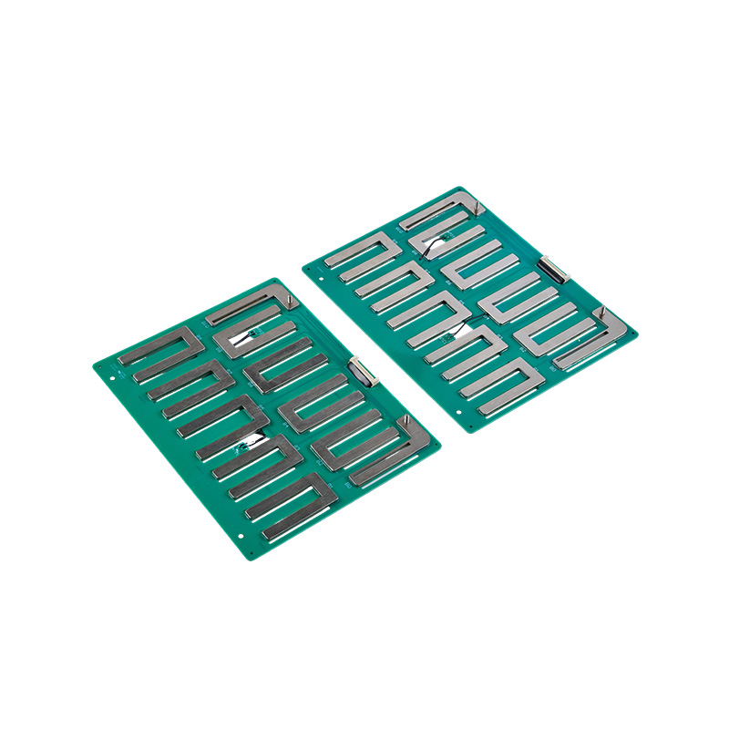
The application of composite laminated busbars in power module integration
Composite laminated busbars are a key enabling technology for power module integration. How composite laminated busbars are applied in power module integration involves their use in connecting power semiconductor devices, capacitors, and other components in a compact, high-performance assembly.
The power module integration requirements
Power modules integrate multiple power semiconductor devices—IGBTs, MOSFETs, and diodes—into a single package. The busbars must provide low-inductance connections to the devices, accommodate the current-carrying requirements, and provide thermal management. The busbar must also provide a means of connecting the module to the external circuitry.
The laminated busbar contribution
The laminated busbar provides the low-inductance connections required for high-speed switching. The low inductance minimizes voltage overshoot and reduces switching losses. The busbar also provides the low-resistance connections required for high-current operation. The thin layers of copper provide a path for heat dissipation, conducting heat away from the power devices. The integration of the busbar into the module package also simplifies the assembly and improves the reliability of the connections.
The integration process
The busbar is integrated into the module package by attaching the power devices to the busbar and then encapsulating the assembly. The busbar may be incorporated into the module substrate, replacing the traditional printed circuit board, or it may be a separate component attached to the substrate. The integration reduces the number of connection points, improving reliability and simplifying the assembly.
The Difference of laminated busbars and traditional connections in power modules
- Laminated busbars: low inductance, low resistance, thermal management, integrated connection, reduced assembly, improved reliability
- Traditional connections (wire bonds, PCB traces): higher inductance, higher resistance, limited thermal management, multiple connection points, more complex assembly, more failure points
- Laminated busbars: enable high-speed switching, reduce switching losses, simplify assembly, improve reliability
- Traditional connections: limit switching speed, increase switching losses, increase assembly complexity, more failure points
FAQ
Q1: Why are laminated busbars better for high-frequency applications?
Laminated busbars reduce skin effect and proximity effect losses, lowering AC resistance and improving efficiency. They also provide low parasitic inductance and controlled capacitance, reducing voltage overshoot and electromagnetic interference.
Q2: How many bending cycles can a laminated flexible busbar withstand?
The bending cycle life depends on the layer thickness and bending radius. For a standard flexible busbar with 0.2 mm layers and a 10x bending radius, the life is typically 10,000–50,000 cycles. High-flex designs can achieve 100,000–1,000,000 cycles.
Q3: What is a composite laminated busbar?
A composite laminated busbar is a busbar that combines multiple layers of conductive material with insulation and other materials to create a single integrated component. It provides electrical connection, thermal management, and structural support in power modules.
Q4: How are laminated busbars used in power modules?
Laminated busbars are used to connect power semiconductor devices, capacitors, and other components in a power module. They provide low-inductance, low-resistance connections with integrated thermal management, enabling high-performance switching.
Q5: What are the advantages of laminated busbars over traditional wiring in power modules?
Laminated busbars offer lower inductance, lower resistance, better thermal management, fewer connection points, simplified assembly, and improved reliability compared to traditional wiring. They also enable higher switching speeds and lower losses.

 English
 Español