The Architecture of Battery Busbars: Cross-Sectional Design, Flexible Connections, and Structural Choices
The cross-sectional design of battery connection busbars
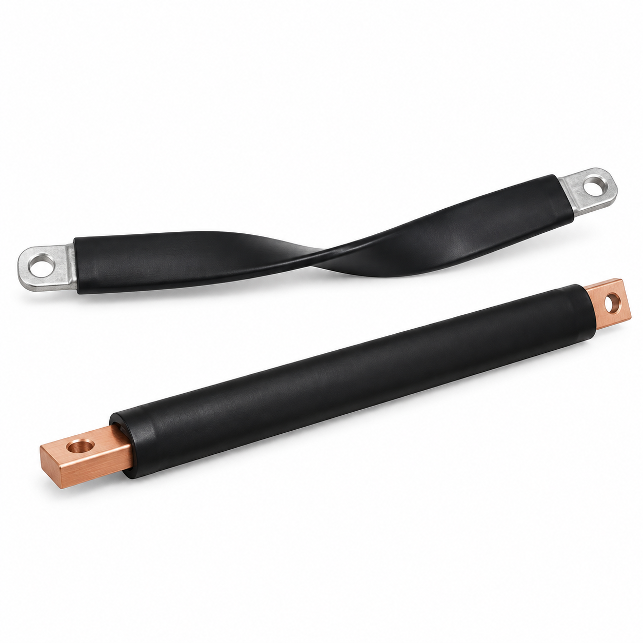
The cross-sectional design of a battery connection busbar determines its current-carrying capacity, voltage drop, and thermal performance. The cross-sectional design of battery connection busbars must balance electrical performance with space constraints and mechanical considerations.
The rectangular cross-section
The rectangular cross-section is the standard for most battery busbar applications. It provides a good balance of current-carrying capacity, space efficiency, and manufacturability. The width-to-thickness ratio affects the current distribution and heat dissipation. A wider busbar has more surface area for cooling, improving the thermal performance.
The laminated cross-section
The laminated cross-section consists of multiple thin layers of metal, typically copper or aluminum, separated by insulation. This construction allows for very high current density in a compact footprint, making it ideal for space-constrained applications.
The round or tubular cross-section
The round or tubular cross-section is less common but may be used in specific applications where bending or routing requirements favor a round profile. The round shape has a smaller surface area for cooling compared to a rectangular busbar of the same cross-sectional area.
The cross-sectional design choices for battery busbars
|
Design Type
|
Cross-Section
|
Application
|
Advantage
|
Limitation
|
|
Rectangular
|
Width-to-thickness ratio optimized for current
|
Standard battery interconnects, main busbars
|
Versatile; good heat dissipation; easy to manufacture
|
Requires space for width
|
|
Laminated
|
Multiple thin layers with insulation
|
High-current, space-constrained applications
|
High current density in small footprint
|
Higher cost; more complex manufacturing
|
|
Round/tubular
|
Circular cross-section
|
Bending and routing applications
|
Bends easily; good for routing
|
Less surface area for cooling
|
|
Tapered
|
Varying cross-section along length
|
Current distribution balancing
|
Optimizes current distribution
|
More complex to manufacture
|
What Is the Flexible Connection Design for EV Battery Busbars?
The flexible connection design for EV battery busbars
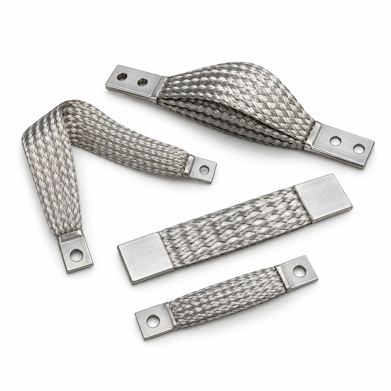
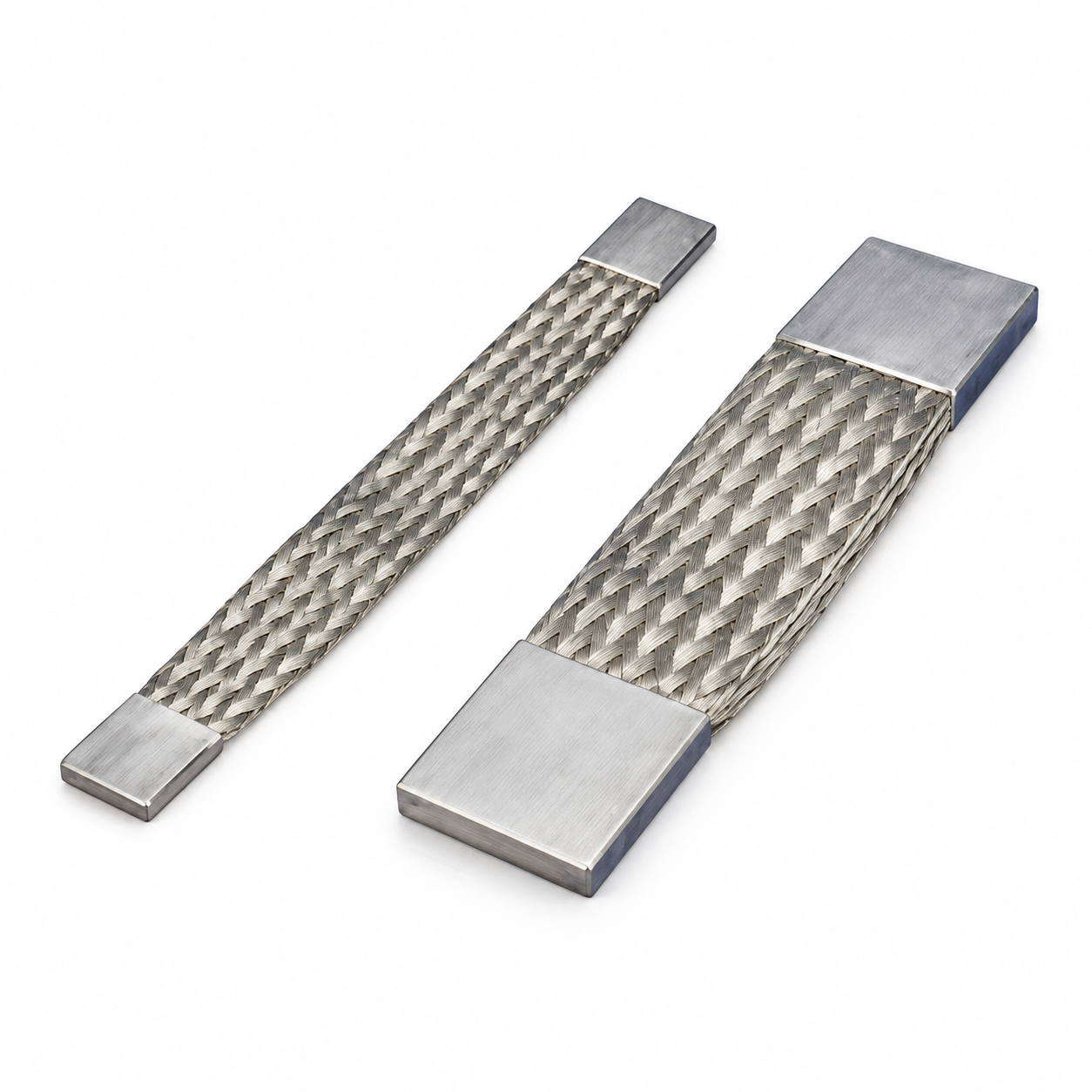
Flexible connections are used in EV battery busbars to accommodate movement, vibration, and thermal expansion. The flexible connection design for EV battery busbars addresses the mechanical challenges of connecting battery cells and modules.
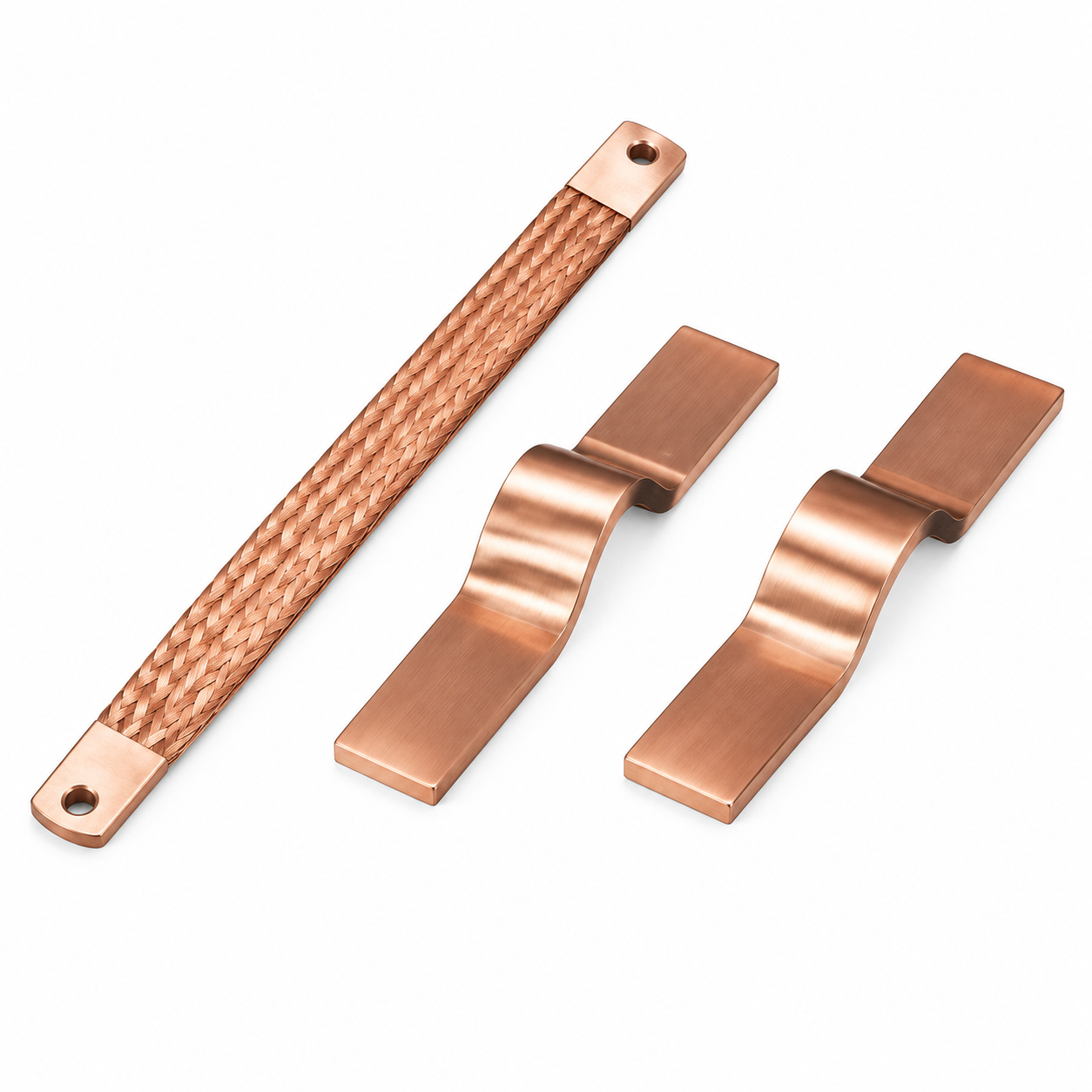
The flexible connection structure
Flexible connections are typically made of multiple layers of thin copper or aluminum foil, stacked and bonded together. The stack allows the connection to flex in multiple directions while maintaining high electrical conductivity. The foil layers are typically 0.1–0.3 mm thick. The connection can be formed into various shapes, such as U-bends and S-bends, to accommodate movement and offset.
The advantages of flexible connections
Flexible connections provide stress relief. They absorb vibration and movement, preventing damage to the battery cells and connections. The low spring rate of the stack ensures minimal force is transmitted to the battery cells. They are also suitable for applications where the connection point must be flexible to allow for thermal expansion and contraction.
The limitations of flexible connections
Flexible connections have higher electrical resistance than solid busbars due to the multiple contact interfaces and the effective conductor length. The resistance is a function of the number of layers and the contact pressure. The connection must be designed to minimize resistance while maintaining flexibility.
The Difference of flexible and rigid connection designs
- Flexible connection: multiple thin layers, allows movement and vibration, lower spring rate, higher resistance, suitable for thermal expansion
- Rigid connection: solid busbar, no flexibility, higher spring rate, lower resistance, not suitable for thermal expansion
Is a Flexible or Rigid Connection Better for the Structural Design of Battery Busbar Connectors?
The Difference of flexible and rigid connections
The choice between flexible and rigid connections for battery busbar connectors depends on the application requirements. Whether a flexible or rigid connection is better for the structural design of battery busbar connectors is determined by the mechanical, thermal, and electrical demands of the specific application.
The case for flexible connections
Flexible connections are better for applications where movement, vibration, or thermal expansion is a concern. The flexibility of the connection prevents stress from being transmitted to the battery cells, extending their life. The connection also reduces the risk of mechanical failure due to fatigue and accommodates misalignment between components.
The case for rigid connections
Rigid connections are better for applications where low resistance, compactness, and high structural strength are required. The solid busbar provides the lowest possible resistance and the most compact design. The connection is simple, reliable, and cost-effective for static applications.
The application-specific considerations
For EV battery packs, both flexible and rigid connections are used. Flexible connections are used for connections that must accommodate relative movement, such as between modules or to external connections. Rigid connections are used for connections where there is no relative movement, such as within a module.
The Difference of flexible and rigid battery busbar connectors
- Flexible connections: better for movement, vibration, and thermal expansion; prevents stress on battery cells; ideal for module-to-module connections
- Rigid connections: better for static applications; lower resistance; more compact; ideal for within-module connections
- Flexible connections: higher resistance; requires careful design to minimize losses; accommodates misalignment
- Rigid connections: lower resistance; no accommodation for movement; higher risk of stress damage
FAQ
Q1: What is the most common cross-section design for battery busbars?
The rectangular cross-section is the most common design for battery busbars. It offers a balance of current-carrying capacity, manufacturability, and compatibility with standard connection hardware.
Q2: Why are flexible connections used in EV battery busbars?
Flexible connections are used to accommodate movement, vibration, and thermal expansion, preventing stress on the battery cells and connections. The flexibility reduces the risk of mechanical failure due to fatigue.
Q3: What are the disadvantages of flexible connections?
Flexible connections have higher electrical resistance than rigid busbars due to the multiple contact interfaces and the effective conductor length. The resistance must be minimized through design, using appropriate materials and contact pressure.
Q4: How do you choose between flexible and rigid connections?
The choice depends on the application. Flexible connections are better for applications with movement, vibration, or thermal expansion. Rigid connections are better for static applications where low resistance and compactness are required.
Q5: Can flexible connections be used for high-current applications?
Yes, flexible connections can be used for high-current applications, but they must be designed carefully to minimize resistance and manage heat dissipation. The number of layers, contact pressure, and material selection are critical.

 English
 Español