The Integration Revolution: How CCS Busbars Are Reshaping Battery Pack Connectivity
How Do Battery Pack Busbars Balance Cross-Sectional Area with Space Constraints?
The balance between cross-sectional area and space constraints
Battery pack busbars must carry high currents while fitting into increasingly limited space. How battery pack busbars balance cross-sectional area with space constraints is a fundamental design challenge in electric vehicle battery engineering.
The cross-sectional area and current-carrying capacity
The cross-sectional area determines the busbar's current-carrying capacity. A larger area means lower electrical resistance, less heat generation, and higher current capacity. The relationship is linear for DC applications, where the resistance is inversely proportional to the area. The area must be sufficient to carry the maximum current without exceeding the allowable temperature rise. For AC applications, the skin effect reduces the effective area at higher frequencies.
The space constraint challenge
The space available for busbars in a battery pack is limited. The busbar must fit within the available envelope while providing the required current-carrying capacity. The cross-section must be optimized for the available space. This often requires a trade-off between the height and width of the busbar.
The strategies for balancing area and space
The strategies for balancing area and space include using a taller busbar with a smaller width, which allows for more efficient use of vertical space. Another strategy is using a laminated busbar, which consists of multiple thin layers, offering high current density in a compact footprint. A third strategy is using a flat, wide busbar, which fits in low-profile spaces but requires more horizontal space. The use of custom cross-sections, tailored to the specific space, is also effective.
Table: cross-sectional strategies for battery pack busbars
|
Strategy
|
Cross-Section
|
Space Efficiency
|
Current Capacity
|
Application
|
|
Tall and narrow
|
Height > width
|
Uses vertical space efficiently
|
Moderate; limited by width
|
Vertical space available
|
|
Wide and flat
|
Width > height
|
Uses horizontal space
|
Good; more surface area for cooling
|
Low-profile applications
|
|
Laminated
|
Multiple thin layers
|
High density; compact
|
Very high
|
Space-constrained, high-current applications
|
|
Custom profile
|
Tailored to space
|
Optimized for available space
|
Optimized for application
|
Specific space constraints
|
Why Are CCS Integrated Busbars Replacing Traditional Wiring Harnesses?
The replacement of traditional wiring harnesses by CCS integrated busbars
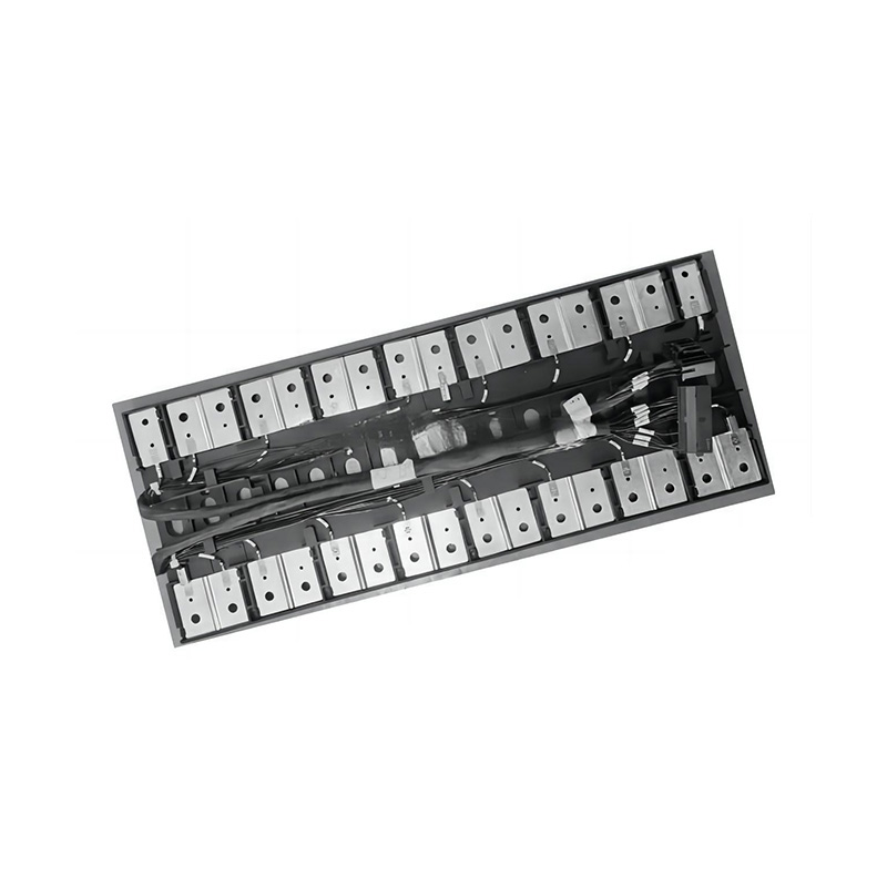
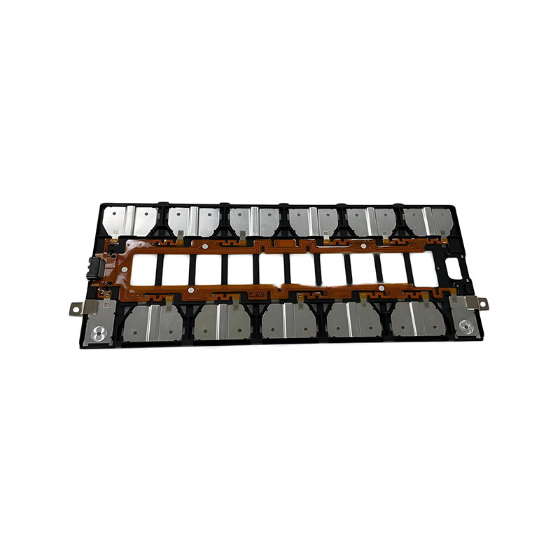
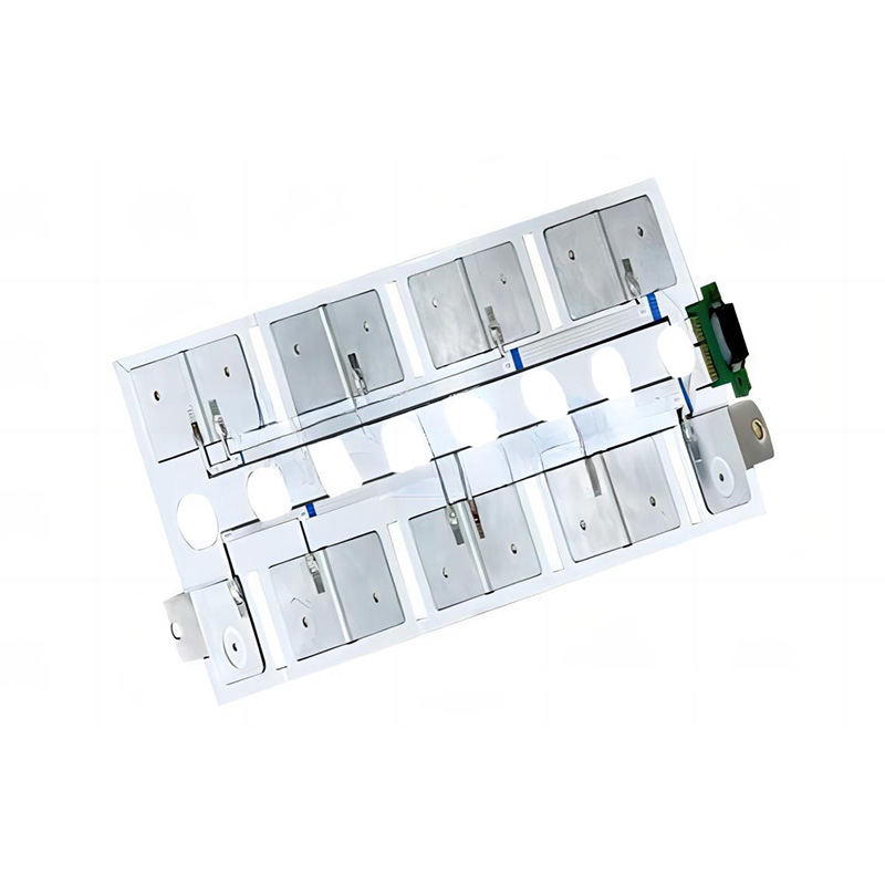
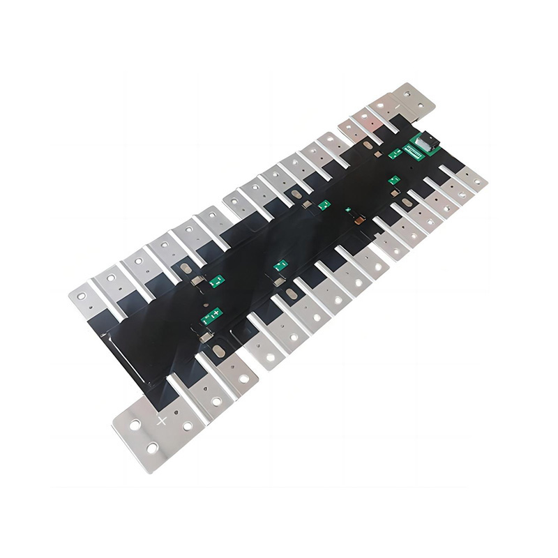
CCS (Cell Contacting System) integrated busbars are rapidly replacing traditional wiring harnesses in EV battery packs. Why CCS integrated busbars are replacing traditional wiring harnesses is driven by the need for increased reliability, reduced assembly time, and improved thermal management.
The reliability advantage
Traditional wiring harnesses have multiple individual wires and connectors, each representing a potential failure point. Connections can loosen over time due to vibration and thermal cycling. CCS integrated busbars eliminate most individual wire connections, reducing failure points and simplifying the assembly process. The integrated design also provides improved vibration resistance, reducing the risk of disconnection during vehicle operation.
The assembly and cost advantage
The assembly of a traditional wiring harness is labor-intensive, requiring manual installation of each wire and connector. The process is also subject to variability, as individual wires must be routed and connected with precision. CCS busbars are pre-assembled, requiring only the attachment of the busbar to the battery cells. The assembly is faster and less variable, reducing assembly time and labor costs.
The thermal management advantage
CCS busbars provide a larger surface area for heat dissipation than individual wires. The busbar acts as a heat sink, conducting heat away from the connections. This improves the thermal management of the battery pack, reducing the temperature rise and extending the life of the components.
The Difference of CCS integrated busbars and traditional wiring harnesses
- CCS integrated busbars: reduced failure points, improved vibration resistance, faster assembly, lower assembly cost, better thermal management
- Traditional wiring harnesses: multiple individual wires and connectors, more failure points, slower assembly, higher assembly cost, limited thermal management
The mainstream adoption of CCS busbars
CCS busbars for battery connections are becoming the mainstream choice in EV battery design. Why CCS busbars for battery connections are becoming the mainstream choice is driven by the demand for higher performance, lower cost, and improved manufacturing efficiency.
The performance advantages
CCS busbars provide lower electrical resistance than traditional wiring harnesses, resulting in reduced voltage drop and heat generation. The improved performance contributes to higher efficiency and longer battery life. The integrated design also allows for better thermal management, reducing the temperature rise in the connection area.
The manufacturing efficiency
The use of CCS busbars simplifies the battery assembly process. The busbar is pre-assembled and tested before installation, reducing the need for manual assembly and testing. The manufacturing process is faster and less variable, reducing assembly time and cost.
The reliability and durability
CCS busbars are more reliable than traditional wiring harnesses due to the reduction in the number of individual connections. The integrated design is also more resistant to vibration and thermal cycling, increasing the durability of the battery pack.
The Difference of CCS busbars and traditional harnesses
- CCS busbars: mainstream choice, lower resistance, better thermal management, faster assembly, lower cost, improved reliability, more durable
- Traditional harnesses: decreasing market share, higher resistance, limited thermal management, slower assembly, higher cost, more failure points, less durable
- CCS busbars: pre-assembled and tested, reduces assembly variability, improves quality control, streamlines the manufacturing process
- Traditional harnesses: manual assembly, more variable, quality control challenges, more labor-intensive
FAQ
Q1: What is a CCS busbar?
A CCS (Cell Contacting System) busbar is an integrated busbar assembly used in EV battery packs to connect individual battery cells. It provides electrical connection, mechanical support, and thermal management in a single integrated component.
Q2: Why are CCS busbars replacing wiring harnesses?
CCS busbars are replacing wiring harnesses due to their lower resistance, improved thermal management, faster assembly, and higher reliability. They also reduce the number of individual connections, minimizing potential failure points.
Q3: How do CCS busbars improve thermal management?
CCS busbars have a larger surface area than individual wires, providing a path for heat dissipation. The busbar acts as a heat sink, conducting heat away from the connection points and improving the overall thermal management of the battery pack.
Q4: Are CCS busbars more reliable than wiring harnesses?
Yes, CCS busbars are more reliable due to the reduction in the number of individual connections. The integrated design is more resistant to vibration and thermal cycling, increasing the durability of the battery pack.
Q5: What is the assembly process for CCS busbars?
CCS busbars are typically pre-assembled and tested before installation. The busbar is attached to the battery cells using methods such as laser welding, ultrasonic welding, or bolted connections. The assembly is faster and less variable than traditional wiring harness assembly.

 English
 Español