 English
 Español

Wire-Harness Plastic-Cover CCS Integrated Busbar for High-Performance Battery Systems
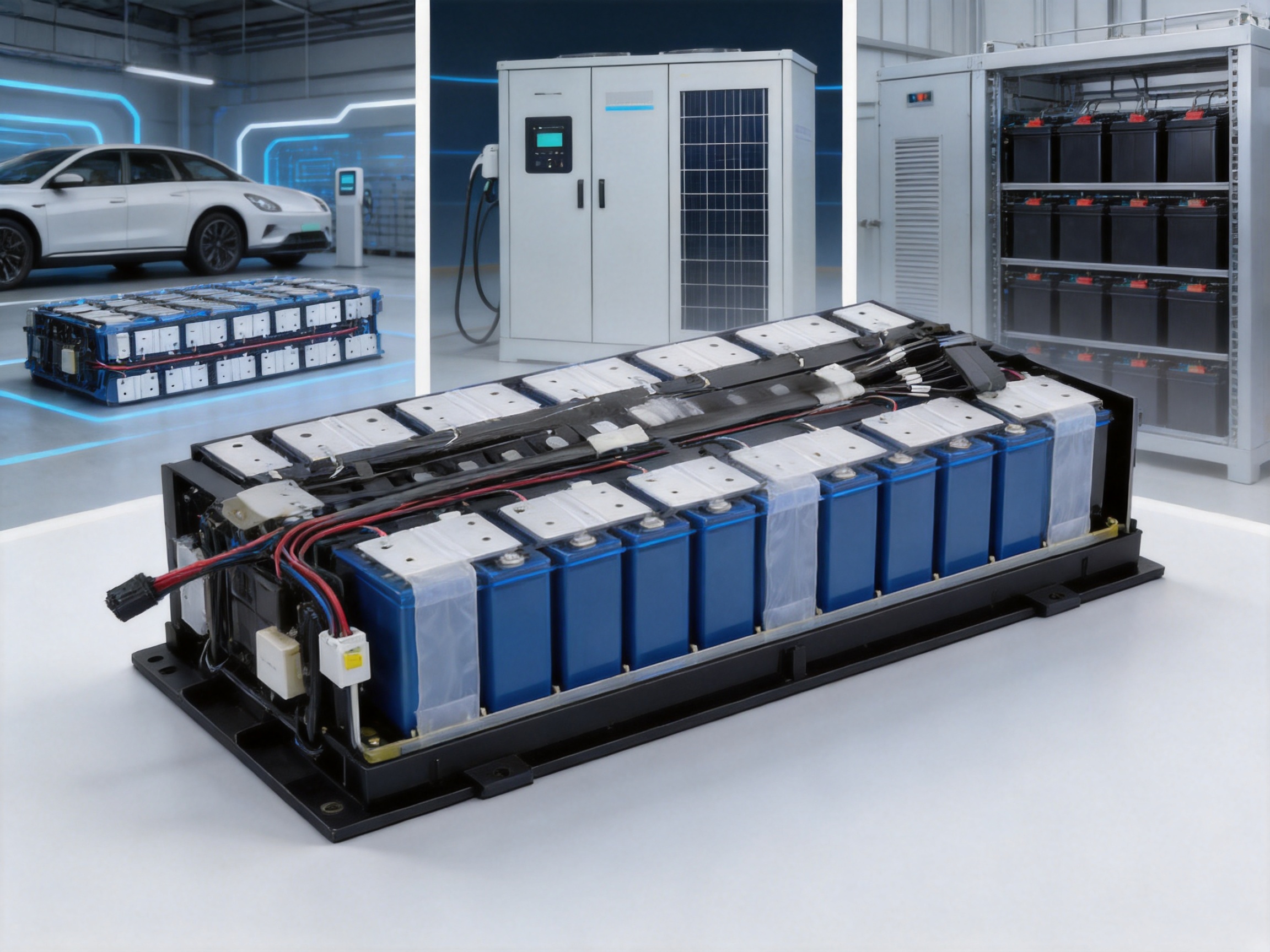
Modern battery packs require more than reliable electrical conduction. They must also provide accurate temperature sensing, dependable voltage monitoring, high insulation performance, efficient thermal management, mechanical stability, and a level of integration suitable for automated production. The wire-harness type plastic-cover Cells Contact System (CCS) integrated busbar is designed to address these requirements in a single battery connection and monitoring assembly.
This integrated CCS solution combines an aluminum busbar, plastic insulation cover, temperature-sensing components, voltage measurement points, and a structured wire harness. It is intended for energy-storage modules, lithium battery packs, electric vehicles, industrial battery systems, and other applications where safe and compact cell interconnection is essential. By integrating multiple functions into one engineered assembly, the product can reduce the need for separate components, simplify pack construction, and improve the consistency of electrical and thermal monitoring.
The system is produced by Zhejiang Zhongyan New Energy Co., Ltd., a manufacturer specializing in new-energy conductive components, battery soft connections, special-shaped connections, and precision electrical assemblies. Its capabilities in material selection, polymer diffusion welding, laser processing, busbar manufacturing, testing, and battery connection design support the development of customized CCS products for demanding applications.
Content
- What Is a Wire-Harness Type Plastic-Cover CCS Integrated Busbar?
- Core Material Configuration
- Functional Advantages of the Integrated Design
- Product Performance Specifications
- Engineering Benefits Compared with Conventional Assemblies
- Manufacturing Process and Quality Control
- Applications in Energy Storage and Electric Mobility
- Company Manufacturing Strengths
- Customization Options
- Installation and Integration Considerations
- Why Select This CCS Solution?
- Frequently Asked Questions
- What is the main purpose of this integrated busbar?
- Why is aluminum used for the busbar?
- What thermistor specifications are available?
- What temperature range can the product support?
- Is the product suitable for high-voltage battery systems?
- What plastic materials can be used for the cover?
- Can the wire harness be customized?
- How does the product support automated manufacturing?
- Does the product provide waterproof protection by itself?
- What information should a customer provide for customization?
- How should the CCS be tested before mass production?
- What makes the product different from a simple busbar?
- Conclusion
- References
- Product: Wire Harness Type Plastic Cover CCS Integrated Busbar
What Is a Wire-Harness Type Plastic-Cover CCS Integrated Busbar?
A Cells Contact System is an integrated electrical and sensing structure installed across a group of battery cells. Its primary purpose is to connect cells electrically while collecting information such as cell voltage and temperature. In a battery module, the CCS generally sits above or alongside the cell array and connects selected cell terminals to the battery management system.
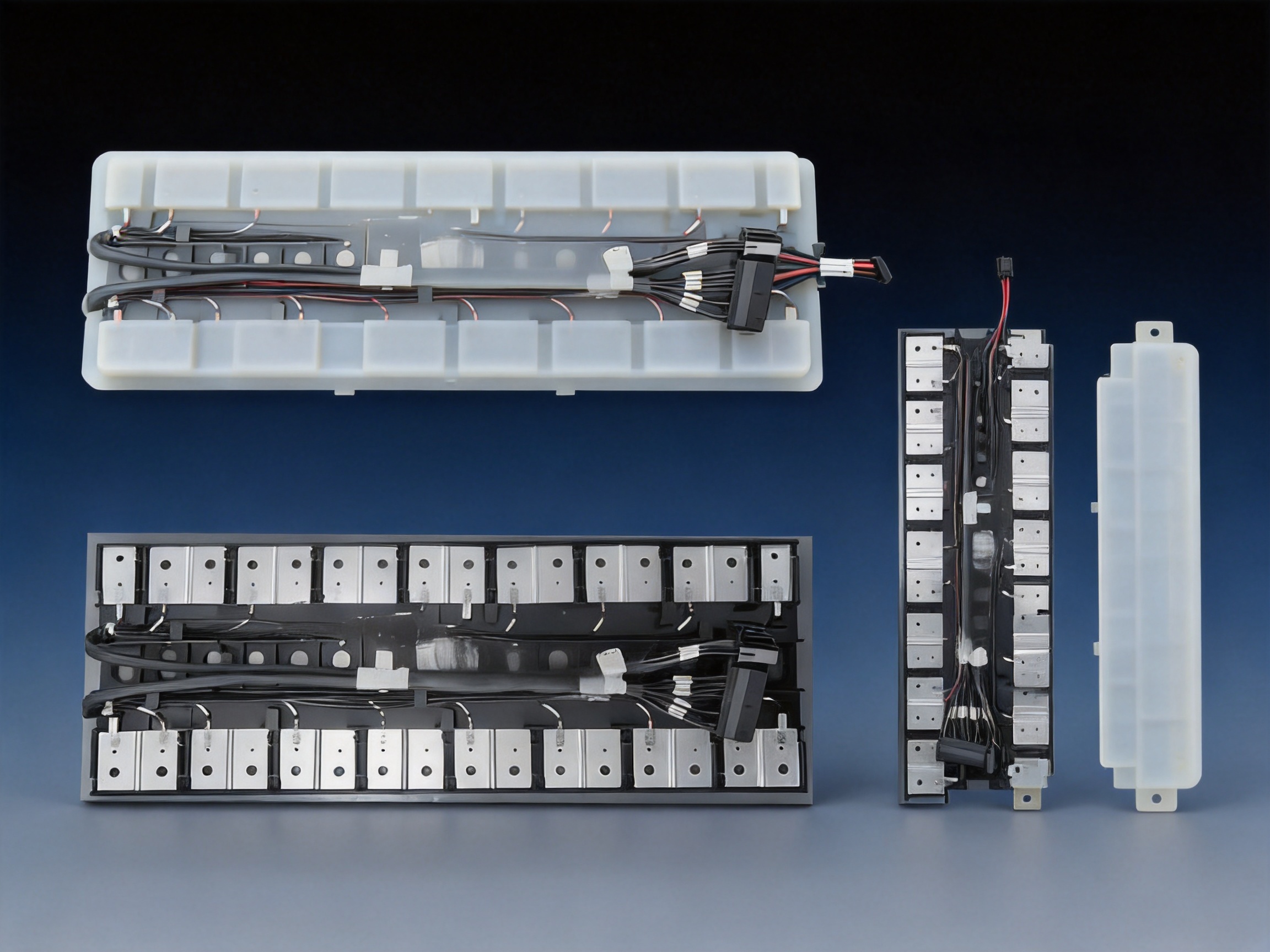
The wire-harness type plastic-cover version uses a molded or formed plastic cover to support and insulate the conductive components. A wire harness connects the sensing points with the module control interface. The design can include aluminum busbars, nickel-plated positive and negative electrodes, thermistors, encapsulated resistors, and other sensing elements. These components are assembled into a compact, organized structure suitable for battery module integration.
Unlike a basic flat busbar that performs only the electrical connection function, an integrated CCS combines power conduction and monitoring functions. This means that the battery pack designer can receive temperature and voltage signals without installing a large number of independent wires, clips, brackets, and insulating parts. The result is a cleaner architecture with fewer loose components and a more controlled assembly process.
The product is especially suitable for energy-storage modules where numerous cells must be interconnected in a limited space. Its flexible wire-harness arrangement supports design changes, different module geometries, and customized output interfaces. This flexibility is valuable for battery manufacturers serving different pack capacities, cell formats, module widths, and system voltage ranges.
Core Material Configuration
Plastic Cover Materials
The plastic cover can be manufactured from PP-GF20, PPO, PC-ABS, or other engineering plastics selected according to the application. These materials provide electrical insulation and mechanical support while maintaining dimensional stability during battery operation.
PP-GF20 is a glass-fiber-reinforced polypropylene material that offers a practical balance of strength, weight, chemical resistance, and cost. The glass-fiber reinforcement improves rigidity compared with unfilled polypropylene, helping the cover maintain its position over the busbar and sensing components.
PPO is suitable for applications requiring strong electrical insulation, low moisture absorption, and good dimensional stability. It can support the requirements of battery environments in which temperature variation, humidity, and long service life are important design considerations.
PC-ABS combines characteristics associated with polycarbonate and ABS. It can provide impact resistance, structural strength, and processability for complex cover geometries. For applications requiring a higher flame-retardant level, material selection and formulation can be adjusted to meet the required safety standard.
Wire-Harness Insulation
The wire harness uses XLPE insulation rated for temperatures up to 150°C. Cross-linked polyethylene offers good electrical insulation, heat resistance, abrasion resistance, and chemical stability. These properties help the harness maintain reliable signal transmission in the thermal and mechanical environment of a battery module.
The wire layout can be configured according to the module’s sensing points and connector position. A customized harness may include voltage-sensing conductors, temperature-sensing conductors, grounding or reference circuits, and the required interface connection to the battery management system. Harness routing can be designed to minimize bending stress, avoid interference with cell surfaces, and maintain a controlled bend radius.
Aluminum Busbar
The primary busbar material is AL1060. This aluminum grade is widely used in conductive components because of its low density, good electrical conductivity, corrosion resistance, and suitability for forming and welding processes. Compared with a copper busbar of similar current capacity, an aluminum busbar can provide a significant weight advantage.
The material may be supplied in an O temper or H24 condition according to the required forming, strength, and assembly process. The selection between material conditions depends on the busbar geometry, bending requirements, welding process, current rating, and mechanical design.
The aluminum busbar provides low electrical impedance and efficient heat dissipation. Its lightweight structure is particularly valuable in electric vehicles and mobile energy-storage systems, where reducing inactive mass can improve overall energy efficiency and system performance.
Nickel-Plated Electrode Areas
The positive and negative electrode areas can be nickel-plated to a thickness of approximately 0.1 mm. Nickel plating supports reliable terminal contact and can improve the compatibility of the aluminum conductor with welding or joining procedures used during module assembly.
Surface treatment also helps address the different material and environmental requirements at the terminal interface. Plating specifications, adhesion, surface cleanliness, and coating uniformity should be controlled during production to ensure stable resistance and consistent weld quality.
Temperature-Sensing Components
The CCS can incorporate thermistors or encapsulated resistors with customized resistance and B-value specifications. Typical options include 10K3930, 10K3435, and 10K3950. The nominal resistance accuracy can reach 1%, while the B-value accuracy can also reach 1%, subject to the selected component and customer specification.
Accurate temperature measurement is vital to battery safety and performance. The battery management system can use temperature data to control charging and discharging current, detect abnormal heating, balance operating conditions, and initiate protective actions when required. A sensing component with stable characteristics and controlled placement can improve the quality of this data.
Functional Advantages of the Integrated Design
Electrical Connection and Monitoring in One Assembly
The most important advantage of an integrated CCS is the combination of current conduction, voltage measurement, and temperature sensing in one organized product. Traditional battery assemblies may use separate busbars, independent sensing wires, individual thermistors, and manually installed insulating sheets. Each additional part increases assembly time and creates more opportunities for incorrect routing or connection.
The integrated design reduces the number of separate components that the battery manufacturer must source, store, position, and inspect. It also enables the supplier to perform more of the assembly and verification work before the product reaches the battery pack production line.
Flexible Structure for Customized Battery Packs
The wire-harness configuration provides more design freedom than a fully rigid printed circuit structure. The harness can be routed around module features, adjusted for different cell spacing, and connected to an interface at a suitable position. This is useful for battery systems with non-standard outlines or multiple module configurations.
Design modifications can include busbar length, terminal position, sensing-point location, wire length, connector selection, plastic cover geometry, mounting features, and the number of monitoring channels. The flexible structure supports customized engineering without requiring the entire battery architecture to be redesigned.
Reliable Signal Transmission
A controlled wire harness helps maintain stable transmission of voltage and temperature signals. Conductors can be selected according to signal requirements, insulation class, operating temperature, and mechanical conditions. The harness is positioned and fixed by the plastic structure, reducing the likelihood of uncontrolled movement, abrasion, or accidental contact with conductive surfaces.
Stable signal transmission is important because the battery management system relies on accurate measurements to make operating decisions. A poor connection, damaged insulation, or inconsistent routing can create false readings or reduce the effectiveness of protection functions. The integrated structure helps create a repeatable sensing network from module to module.
Effective Moisture and Water Resistance
The product is designed to provide excellent waterproof and moisture-resistant performance when the selected materials, encapsulation method, connector system, and installation design are correctly matched to the application. The plastic cover protects internal conductive areas and sensing components from incidental environmental exposure.
Water resistance is particularly important in vehicle battery systems, outdoor energy-storage cabinets, and industrial environments where condensation, humidity, cleaning fluids, or accidental liquid exposure may occur. Final protection depends on the complete battery module design, including enclosure sealing, connector protection, drainage, and validation testing.
Improved Insulation and Safety
The plastic cover separates conductive components from surrounding structures and helps prevent unintended contact. The system is specified with an insulation resistance greater than 500 megohms at 1000 VDC. Its dielectric withstand performance is specified at 3000 VAC for 60 seconds with leakage current below 1 mA, while certain finished-product configurations can withstand voltages up to 4200 VDC.
These values should be understood as product or configuration specifications that must be confirmed against the final design, test method, and customer acceptance standard. Different battery architectures may require different test voltages, durations, ramp rates, and fixture arrangements. The appropriate validation protocol should therefore be established during engineering approval.
Lightweight Conductive Structure
Aluminum provides a lower-density alternative to copper for many busbar applications. In a large battery module containing multiple conductors, this weight reduction can be significant. Lower mass can simplify handling, reduce structural loading, and support the design objectives of electric vehicles and mobile energy-storage equipment.
Aluminum also provides effective heat dissipation. When the busbar geometry is properly designed, heat generated by current flow can be distributed through the conductor and transferred toward the surrounding structure. Thermal behavior depends on current, cross-sectional area, contact resistance, ambient temperature, mounting conditions, and duty cycle.
High Automation Potential
Laser welding and controlled assembly processes support a high degree of automation. Automated joining can improve positioning accuracy, repeatability, appearance, and production efficiency compared with highly manual connection methods.
The integrated product can arrive at the battery assembly line as a preconfigured module. Operators or automated equipment can place the CCS onto the cell array, complete the required terminal connections, and perform electrical and functional inspections. This reduces the number of individual operations performed near the cells and helps standardize production.
Product Performance Specifications
The following table summarizes the principal specifications provided for the wire-harness type plastic-cover CCS integrated busbar. Actual values may vary according to the battery design, selected materials, sensing components, and customer requirements.
| Item | Specification or Option | Engineering Significance |
|---|---|---|
| Busbar material | AL1060 aluminum | Low weight, low impedance, and efficient heat dissipation |
| Busbar condition | O temper or H24 condition | Selected according to forming and mechanical requirements |
| Electrode surface | Nickel-plated positive and negative areas, approximately 0.1 mm | Supports terminal joining and interface reliability |
| Plastic cover | PP-GF20, PPO, PC-ABS, or equivalent specified material | Insulation, structural support, and environmental protection |
| Wire insulation | XLPE, rated up to 150°C | Heat-resistant signal transmission |
| Thermistor options | 10K3930, 10K3435, 10K3950, or customized type | Temperature monitoring matched to the battery management system |
| Resistance accuracy | R25°C accuracy of 1% | Supports consistent temperature measurement |
| B-value accuracy | 1%, customizable | Improves temperature calculation accuracy |
| Operating temperature | -40°C to 125°C | Suitable for demanding battery operating environments |
| Insulation resistance | Greater than 500 megohms at 1000 VDC | High resistance against leakage through insulation |
| Withstand voltage | 3000 VAC for 60 seconds, leakage current below 1 mA | Dielectric safety verification |
| Finished-product voltage capability | Up to 4200 VDC in specified configurations | Supports high-voltage validation requirements |
| Flame retardancy | UL94-V0 requirement | Reduces flame propagation risk when the specified material is used |
| Output signal | Analog signal output | Provides sensing information to the battery management system |
| Joining process | Laser welding and related precision methods | Supports repeatable, clean, and automated assembly |
Engineering Benefits Compared with Conventional Assemblies
Fewer Separate Parts
A conventional module may require independent busbars, sensor wires, insulating plates, clips, brackets, and terminal covers. Each part must be correctly selected and installed. The CCS integrates many of these functions, reducing the part count and simplifying the bill of materials.
Fewer parts can also reduce inventory complexity. A battery manufacturer can work with a defined CCS assembly rather than coordinating multiple suppliers for separate conductive, insulating, and sensing components. This may simplify procurement and improve production planning.
Reduced Assembly Risk
Loose wires and manually installed sensing components can be vulnerable to incorrect routing, pinching, insufficient fixation, or contact with sharp edges. The plastic cover and harness arrangement provide a controlled path for the conductors and help keep the system in its intended position.
By moving more assembly work to a specialized supplier, the battery manufacturer can reduce the number of delicate tasks performed directly over the cell array. The result is a more repeatable assembly sequence and a lower risk of accidental damage during pack construction.
Better Space Utilization
Battery modules are designed around compact cell spacing and limited vertical clearance. An integrated CCS can be shaped to match the available envelope. The cover, busbar, and wire harness can be designed together instead of being installed independently with overlapping clearances.
This coordinated design can free space for other components, improve enclosure utilization, and support higher packing efficiency. In electric vehicles and stationary storage systems, the ability to use available space effectively can contribute to greater energy capacity within the same overall enclosure.
Consistent Measurement-Point Positioning
Temperature and voltage measurement quality depends partly on where the sensing components are located. A pre-engineered CCS places the sensors at defined positions relative to the cell terminals or module structure. This helps reduce variation from one module to another.
Consistent positioning also supports repeatable thermal modeling and battery management system calibration. When sensor locations are uncontrolled, measured values may not accurately represent the temperature of the intended cell area. A controlled CCS structure helps create a more predictable relationship between the sensor reading and the cell condition.
Improved Production Traceability
As an integrated product, the CCS can be inspected and documented as a defined assembly. Incoming inspection may include dimensional checks, material verification, resistance measurement, continuity testing, insulation testing, appearance inspection, and welding-quality verification.
Traceability can be organized around production batches, material lots, sensor specifications, welding parameters, and test records. This is valuable for high-volume battery manufacturing, where consistent quality and rapid fault analysis are essential.
Manufacturing Process and Quality Control
Engineering Design and Product Customization
Manufacturing begins with a review of the battery module requirements. Important input data includes cell type, cell dimensions, terminal arrangement, nominal and maximum current, module voltage, temperature range, available installation space, connector position, sensing-channel count, and the required communication interface.
Engineers then determine the busbar cross section, terminal geometry, cover layout, harness route, sensor placement, joining method, and mounting features. The design should account for electrical clearance, creepage distance, thermal expansion, mechanical vibration, assembly tolerance, and service conditions.
Three-dimensional modeling and prototype evaluation can be used to confirm the fit between the CCS and the battery module. Design reviews should examine interference with cell housings, end plates, cooling components, fasteners, and protective covers. Early analysis reduces the risk of late-stage modifications after tooling or mass production has begun.
Aluminum Busbar Processing
AL1060 aluminum material is cut, formed, and shaped according to the approved design. The processing route may include blanking, bending, punching, forming, edge treatment, and cleaning. Dimensional control is important because small deviations in terminal position can affect module assembly and welding alignment.
Edges should be managed carefully to reduce the possibility of damaging wire insulation or plastic components. The busbar surface must be sufficiently clean before plating or joining. Contamination, oxidation, oil, or particles can negatively affect welding quality and electrical resistance.
Nickel Plating and Surface Preparation
Specified positive and negative electrode areas receive nickel plating. Coating thickness, coverage, adhesion, and surface appearance should be monitored. The plating process must be compatible with the intended welding method and should provide a stable interface during the product’s operating life.
After plating, the parts may undergo cleaning and inspection before assembly. Surface cleanliness is especially important for battery components. The specified cleanliness level of RFU below 100 indicates a strong emphasis on controlling residue and contamination. Final cleanliness requirements should be defined using the customer’s inspection method and acceptance criteria.
Plastic Cover Manufacturing
The plastic cover may be injection molded or otherwise formed using the selected engineering polymer. Tooling must provide the required dimensional accuracy, wall thickness, fixing features, wire channels, sensor pockets, and clearance zones.
Material drying, molding temperature, injection pressure, cooling conditions, and mold maintenance all influence the quality of the finished cover. Warpage or shrinkage can affect busbar alignment, sensor placement, and module installation. For flame-retardant materials, the formulation and processing conditions must be controlled to preserve the intended safety performance.
Wire-Harness Preparation
XLPE-insulated wires are cut to length, stripped where required, terminated, marked, and routed according to the approved harness drawing. The harness must be checked for conductor continuity, correct channel sequence, insulation damage, terminal retention, and connector orientation.
Wire routing should avoid sharp bending, excessive tension, and contact with unprotected metal edges. Fixing features may be incorporated into the cover to maintain the harness position during transportation, installation, and vibration. The final bend radius should be compatible with the wire specification.
Sensor Installation
Thermistors or encapsulated resistors are installed at designated measurement points. The component type must match the approved resistance curve and B-value. Sensor attachment should provide stable thermal contact without placing excessive mechanical stress on the component or its leads.
Because temperature measurement is affected by thermal contact, sensor position, surrounding materials, and airflow, the installation method should be validated with representative battery cells. The selected sensor design can be customized for response speed, packaging form, mechanical protection, and connection method.
Laser Welding and Precision Joining
Laser welding can join selected conductive components with high positional accuracy and limited heat input. Compared with less controlled joining methods, a properly developed laser process can produce clean welds with consistent penetration and repeatable appearance.
Welding parameters may include laser power, pulse or continuous mode, travel speed, focus position, shielding conditions, and overlap pattern. Process validation should include tensile or peel testing where appropriate, metallographic examination, electrical resistance measurement, and visual inspection.
Laser welding is also compatible with automated production. Fixtures can position the components while sensors and control systems monitor the process. This supports a high degree of repeatability, which is particularly important when the CCS is produced in large quantities for battery module manufacturing.
Electrical and Safety Testing
Finished assemblies can be subjected to continuity testing, resistance testing, insulation resistance testing, dielectric withstand testing, temperature-sensor verification, connector inspection, and visual examination. Tests are selected according to the product configuration and customer quality plan.
The insulation resistance test verifies that conductive paths remain electrically isolated from the specified reference points. The withstand-voltage test checks the ability of the insulation system to tolerate a defined electrical stress for a specified time. These tests must be conducted with suitable fixtures and controlled procedures to protect operators and prevent damage to the assembly.
Cleanliness and Final Inspection
Battery components require strict control of particles, oil, metal residues, and other contaminants. Final cleaning and inspection can be carried out before packaging. Cleanliness testing may use extraction, particle counting, microscopy, or another customer-approved method.
Final inspection also verifies dimensions, cover appearance, busbar alignment, plating condition, wire routing, connector labeling, sensor specifications, and packaging protection. The product should be packed in a way that prevents deformation, abrasion, moisture exposure, and contamination during storage and transportation.
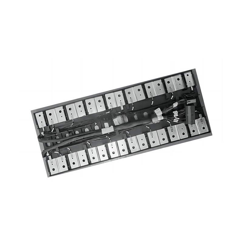
Wire Harness Type Plastic Cover CCS Integrated Busbar
Applications in Energy Storage and Electric Mobility
Stationary Energy-Storage Modules
Stationary energy-storage systems contain many battery cells arranged into modules and racks. These systems require reliable cell interconnection and continuous monitoring during charging, discharging, balancing, and standby operation.
The CCS integrated busbar can support modular battery designs by combining conductive pathways and sensing circuits in a compact structure. The plastic cover helps organize the assembly, while the temperature sensors provide the battery management system with information needed for thermal supervision.
In outdoor or industrial storage applications, the environmental design may need to address humidity, condensation, dust, vibration, and repeated temperature cycling. The CCS should therefore be validated as part of the complete battery enclosure and not treated as an isolated component.
Electric Vehicles
Electric vehicles place strong emphasis on low mass, compact packaging, vibration resistance, high-voltage insulation, and production consistency. The aluminum busbar and flexible harness structure support these objectives.
Automotive battery modules may use different cell formats and geometries, including prismatic, cylindrical, or pouch-cell arrangements. A customized CCS can be adapted to the terminal configuration and available module space. Its integrated form can also simplify the connection between the cell array and the battery management system.
Industrial Battery Systems
Forklifts, automated guided vehicles, backup-power systems, railway equipment, and industrial machinery may use battery packs that require robust sensing and electrical connection. These applications can benefit from a structured assembly that is easier to install and inspect than a collection of loose wires and separate busbars.
The operating temperature range of -40°C to 125°C provides a broad design basis for many industrial applications. Final suitability depends on the actual duty cycle, enclosure temperature, current profile, vibration level, chemical exposure, and applicable industry standards.
Specialized Lithium Battery Packs
Customized lithium battery packs often have non-standard shapes or limited installation space. The flexible wire-harness configuration can accommodate unusual module layouts, side-entry connectors, offset sensing points, and special cover profiles.
This adaptability allows the CCS to be developed as part of the battery pack rather than selected as a generic component after the pack architecture has already been fixed. Early supplier involvement can improve the balance between cell arrangement, electrical performance, manufacturability, and serviceability.
Company Manufacturing Strengths
Zhejiang Zhongyan New Energy Co., Ltd. focuses on new-energy conductive components and precision connection systems. Its product scope includes high-voltage electrical copper foil soft connections, special-shaped soft connections, battery soft connections, and other components used in power transmission, electric vehicles, rail transit, communication, and energy-storage applications.
The company was established in 2022 and has developed its capabilities around battery connection technologies and new-energy precision components. Its engineering team combines experience in material science, product design, processing, testing, and manufacturing. This combination is important because a CCS is not simply a stamped conductor or a plastic cover; it is a multi-material system requiring coordination among electrical, thermal, mechanical, and manufacturing disciplines.
The company has invested in polymer diffusion welding and laser technology. These technologies support the production of conductive components with low internal resistance and high reliability. They also provide a foundation for designing specialized connections according to the customer’s cell architecture and module requirements.
Advanced manufacturing equipment helps support repeatable production and controlled process parameters. Modern quality-management practices can be applied to material inspection, in-process control, finished-product testing, cleanliness management, and traceability. Such systems are essential when supplying components for high-voltage battery applications.
The company’s development strategy includes building capabilities across materials science, precision machining, testing, and verification. Its knowledge of battery cells and connection systems also supports the expansion into lithium battery manufacturing and integrated battery-cell and connection-system design.
For customers, this integrated technical background can reduce communication barriers between the battery design team and the busbar supplier. Instead of treating the CCS as an isolated purchased part, the supplier can participate in the development of the complete connection and monitoring architecture.
Customization Options
The product can be customized for different battery modules and system requirements. Typical customization areas include busbar length, width, thickness, terminal shape, hole pattern, bend angle, nickel-plating area, cover geometry, mounting features, harness length, wire color, connector type, sensor position, and signal-channel arrangement.
Thermistors can be selected according to nominal resistance, B-value, accuracy, response characteristics, and packaging structure. Common options include 10K3930, 10K3435, and 10K3950, while other specifications can be developed for a particular battery management system.
The insulation system can also be adapted. PP-GF20, PPO, PC-ABS, PA66, or another approved flame-retardant material may be considered based on temperature, mechanical strength, chemical exposure, dimensional stability, and regulatory requirements.
Customers should provide complete technical information during the design stage. Useful information includes cell drawings, terminal material, welding method, current rating, voltage rating, module dimensions, number of cells, temperature-monitoring strategy, connector definition, environmental conditions, and required tests.
Prototype samples should be evaluated before mass production. Prototype validation can include dimensional fit, terminal joining, sensor response, insulation performance, vibration resistance, thermal cycling, humidity exposure, cleanliness, and compatibility with the battery management system.
Installation and Integration Considerations
The CCS should be installed according to a controlled work instruction. The cell terminals and busbar contact areas must be clean and correctly aligned before joining. Excessive force should not be applied to the plastic cover, wire harness, sensor leads, or connector.
Clearance and creepage distances must remain consistent with the battery system voltage and applicable safety requirements. Conductive components should not be placed in a way that allows contact with the enclosure or neighboring structures under vibration or thermal expansion.
Connector routing should avoid areas of high heat, moving parts, sharp edges, and possible coolant contact unless the connector and protection system are specifically designed for those conditions. The harness should be supported at suitable intervals without being compressed or bent beyond its permitted radius.
Welding or fastening procedures should be validated for the selected cell terminal and busbar combination. Aluminum, nickel, copper, and cell-terminal materials may require different process parameters. Welding quality should be checked through appropriate destructive and non-destructive methods.
After installation, the module should undergo continuity, polarity, insulation, and sensor verification. The battery management system should confirm that each measurement channel corresponds to the correct cell or sensing location. Incorrect channel sequence can produce misleading measurements even when the physical assembly appears intact.
Why Select This CCS Solution?
The wire-harness type plastic-cover CCS integrated busbar offers a balanced combination of electrical conduction, temperature measurement, insulation, mechanical support, and production flexibility. Its principal value lies in integration: several functions that are often handled by separate components are brought together into one engineered assembly.
The use of AL1060 aluminum helps reduce mass while providing low impedance and heat dissipation. The XLPE wire harness supports stable signal transmission at elevated temperature. The engineering-plastic cover provides insulation and structural organization. Nickel-plated electrode areas support reliable terminal joining, while laser welding enables repeatable production.
The product also offers a practical customization path. Battery manufacturers can request changes to the geometry, sensing configuration, connector arrangement, materials, and output structure. This is more suitable for specialized battery systems than a one-size-fits-all component that may require additional adapters or manual modifications.
Compared with a conventional collection of independent busbars and sensing wires, the integrated CCS can improve assembly efficiency, reduce loose-part risk, enhance measurement-point consistency, and simplify inspection. When supported by appropriate process validation and quality control, it can contribute to a safer, cleaner, and more scalable battery manufacturing process.
Frequently Asked Questions
What is the main purpose of this integrated busbar?
The main purpose is to connect battery cells electrically while also supporting voltage and temperature measurement. The assembly combines aluminum busbars, a protective plastic structure, temperature-sensing components, and a wire harness for connection to the battery management system.
Why is aluminum used for the busbar?
AL1060 aluminum offers low density, good conductivity, low impedance, corrosion resistance, and effective heat dissipation. It can reduce the weight of the battery module compared with a similarly sized copper conductor, although the final current capacity and geometry must be designed for the application.
What thermistor specifications are available?
Typical thermistor options include 10K3930, 10K3435, and 10K3950. Resistance accuracy and B-value accuracy can reach 1%, and customized specifications may be available according to the battery management system and temperature-measurement requirements.
What temperature range can the product support?
The stated operating temperature range is -40°C to 125°C. The complete battery module must also be evaluated because actual performance depends on cell temperature, enclosure conditions, current profile, connector limitations, and the selected plastic and wire materials.
Is the product suitable for high-voltage battery systems?
Yes. The product is specified with an insulation resistance greater than 500 megohms at 1000 VDC and a dielectric withstand specification of 3000 VAC for 60 seconds with leakage current below 1 mA. Certain finished-product configurations can withstand up to 4200 VDC. The exact rating must be confirmed for the final design and validation method.
What plastic materials can be used for the cover?
Available material options include PP-GF20, PPO, PC-ABS, and other approved engineering plastics such as PA66 where appropriate. The selection depends on flame retardancy, mechanical strength, temperature resistance, moisture exposure, dimensional stability, and customer standards.
Can the wire harness be customized?
Yes. Wire length, routing, conductor arrangement, connector type, terminal format, labeling, sensing-channel count, and output position can be customized according to the module layout and battery management system interface.
How does the product support automated manufacturing?
The busbar and sensor assembly can be designed for fixture-based production, laser welding, automated inspection, and preassembled module installation. Controlled joining and repeatable component positioning help reduce manual operations and improve production consistency.
Does the product provide waterproof protection by itself?
The product is designed to provide strong moisture and waterproof performance when the selected materials, cover structure, encapsulation, connectors, and installation conditions are properly matched. However, the final water-ingress rating belongs to the complete battery module or enclosure and must be validated as a system.
What information should a customer provide for customization?
Customers should provide cell drawings, terminal specifications, module dimensions, current and voltage requirements, sensor locations, connector information, operating temperature, environmental conditions, welding method, insulation requirements, cleanliness limits, and applicable validation standards.
How should the CCS be tested before mass production?
Recommended validation may include dimensional inspection, electrical continuity, resistance measurement, polarity verification, temperature-sensor accuracy, insulation resistance, dielectric withstand, welding strength, thermal cycling, vibration, humidity exposure, cleanliness, connector retention, and module-level fit testing.
What makes the product different from a simple busbar?
A simple busbar primarily provides electrical conduction. This integrated CCS adds wire-based monitoring, thermistors, insulation, mechanical support, terminal organization, and an interface for the battery management system. It is therefore a broader battery connection and monitoring solution rather than only a conductor.

Conclusion
The wire-harness type plastic-cover CCS integrated busbar is designed for battery systems that require dependable electrical connection, accurate thermal monitoring, high-voltage insulation, compact packaging, and efficient manufacturing. By combining an AL1060 aluminum busbar, nickel-plated electrode areas, XLPE-insulated wires, engineering-plastic protection, and customized thermistors, the product addresses multiple battery-module requirements in one coordinated assembly.
Its flexible structure supports customized cell layouts and design modifications, while laser welding and automated production methods support repeatable quality. The lightweight aluminum construction can reduce inactive mass, and the integrated sensing architecture can simplify the connection between the cell array and the battery management system.
Zhejiang Zhongyan New Energy Co., Ltd. brings together experience in new-energy conductive components, battery soft connections, precision manufacturing, polymer diffusion welding, laser processing, and product verification. This combination provides a foundation for developing customized CCS products for electric vehicles, energy-storage systems, industrial batteries, and specialized lithium battery packs.
For customers seeking a reliable alternative to separate busbars, loose sensing wires, and manually installed insulating components, an integrated CCS can improve design organization, assembly efficiency, measurement consistency, and production scalability. Final performance should always be verified against the completed battery module, but the product provides a strong technical platform for safe and highly integrated battery connection systems.
References
1. IEC 60664-1, Insulation Coordination for Equipment within Low-Voltage Systems.
2. IEC 62619, Secondary Cells and Batteries Containing Alkaline or Other Non-Acid Electrolytes—Safety Requirements for Secondary Lithium Cells and Batteries for Use in Industrial Applications.
3. UL 94, Tests for Flammability of Plastic Materials for Parts in Devices and Appliances.
4. ISO 16750, Road Vehicles—Environmental Conditions and Testing for Electrical and Electronic Equipment.
5. Aluminum Association, Aluminum Standards and Data.
6. Battery management system design principles for lithium-ion battery monitoring and protection.
7. Internal product specifications for wire-harness type plastic-cover CCS integrated busbar assemblies.
8. Manufacturer engineering information concerning AL1060 busbars, XLPE wire harnesses, nickel-plated terminals, thermistor integration, laser welding, and battery connection systems.
Product: Wire Harness Type Plastic Cover CCS Integrated Busbar

Driven by the development of new energy and aiming for "zero carbon".
Copyright © Zhejiang Zhongyan New Energy Co., Ltd. All Rights Reserved.
