 English
 Español

High-Voltage Bolt Connectors for Safe, High-Current Battery and Energy Storage Systems
Modern battery systems require connection components that can carry substantial current, withstand high direct-current voltage, remain mechanically stable over long service periods, and support efficient installation. As energy storage cabinets, electric vehicles, charging equipment, and industrial power systems become more powerful, the requirements for high-voltage connectors continue to increase. A connector must do more than join two conductors. It must maintain a dependable electrical path, control insulation distances, resist heat and vibration, simplify field wiring, and support safe integration into a complete battery architecture.
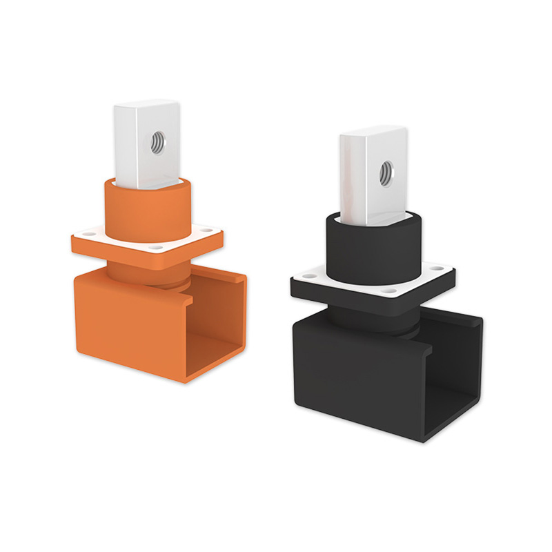
The Bolt Connector is a dedicated wall-mounted, through-panel connector designed for high-voltage battery and energy storage applications. Its bolt-based connection method, square through-wall structure, high-conductivity metal terminal, and flame-retardant PA66 housing provide a practical solution for high-current power transmission. The connector is suitable for high-voltage battery packs, energy storage systems, high-voltage boxes, industrial and commercial energy storage cabinets, new energy vehicle wiring harnesses, and other equipment that requires a reliable high-current connection through an enclosure wall.
Available configurations cover a wide range of current and voltage requirements. Depending on the selected model, the product family supports rated currents from approximately 100 A to 400 A, rated voltages from 600 V DC to 1500 V DC, and dielectric strength levels from 3000 V AC to 4000 V AC. Terminal screw options include M6, M8, and M10, while M4 mounting screws are used for panel installation. This range allows equipment designers to select a connector that matches the electrical and mechanical requirements of a specific battery or power-distribution system.
Bolt Connector
1. The Role of a Bolt Connector in High-Voltage Power Systems
In a battery storage system, electrical energy must move between cells, modules, battery racks, protection devices, contactors, busbars, inverters, and external loads. Each transition point introduces the possibility of electrical resistance, mechanical loosening, insulation failure, or installation error. A properly engineered bolt connector reduces these risks by combining a secure conductive terminal with a robust insulated housing and a controlled panel-mounting structure.
The Bolt Connector is primarily designed as a through-wall connection point. Instead of routing an unprotected conductor through an enclosure opening, the connector creates a dedicated insulated passage between the internal and external sides of a high-voltage box, battery enclosure, or energy storage cabinet. This arrangement helps maintain enclosure organization and supports a cleaner separation between internal power circuits and external harnesses.
The square wall-through construction offers several practical benefits. It provides a defined mounting position, helps prevent unwanted rotation during installation, and supports stable positioning of the terminals. The design is suitable for applications where the connector must be installed on the wall of a high-voltage box or energy storage cabinet while maintaining controlled insulation around the conductive components.
The bolt connection method is especially useful in high-current applications. A properly tightened bolt can generate consistent contact pressure between conductive surfaces, reducing the risk of intermittent contact caused by weak spring force or poor terminal engagement. It also allows technicians to inspect, tighten, or replace the connection using familiar tools and standard installation procedures.
For equipment manufacturers, this type of connector can simplify the transition from internal busbars or battery terminals to external high-voltage wiring harnesses. For system integrators, it offers a standardized connection point that can be incorporated into cabinet layouts, battery racks, and high-voltage distribution assemblies.
2. Product Structure and Main Materials
PA66 Flame-Retardant Insulating Housing
The insulating housing is manufactured from PA66 plastic with a UL94 V-0 flame-retardant grade. PA66 is commonly used in demanding electrical and mechanical applications because it combines good mechanical strength, dimensional stability, and resistance to elevated operating temperatures. The V-0 classification provides an important layer of fire-safety performance for electrical equipment, although the complete system must still be evaluated according to its enclosure design, operating environment, wiring method, and applicable safety standards.
The housing surrounds and supports the conductive elements while helping maintain the required separation between energized parts and the equipment enclosure. Its insulating function is particularly important in high-voltage battery systems, where accidental contact or insufficient clearance can cause serious safety hazards.
The housing also contributes to mechanical stability. The connector must remain fixed to the panel while cables, busbars, and terminal hardware are being installed or serviced. A rigid, accurately formed housing helps keep the terminal aligned and reduces the risk of movement that could place stress on the conductor or mounting screws.
Nickel-Plated H59 Brass Conductor
The conductive terminal uses H59 brass with nickel plating. Brass provides a useful combination of electrical conductivity, strength, machinability, and resistance to mechanical deformation. These properties are valuable in a bolted connection, where the terminal must withstand tightening force and maintain a stable interface over repeated installation or service operations.
Nickel plating improves the surface properties of the brass conductor. It can help protect the base material against oxidation and environmental exposure while providing a durable contact surface. In high-current equipment, surface condition is important because contamination, corrosion, or uneven contact can increase resistance and generate additional heat.
The combination of H59 brass and nickel plating is therefore intended to support reliable current transfer and long-term mechanical performance. The material selection also supports consistent machining of the terminal, including the production of threaded or bolted features required for M6, M8, or M10 connection hardware.
Bolted Electrical Interface
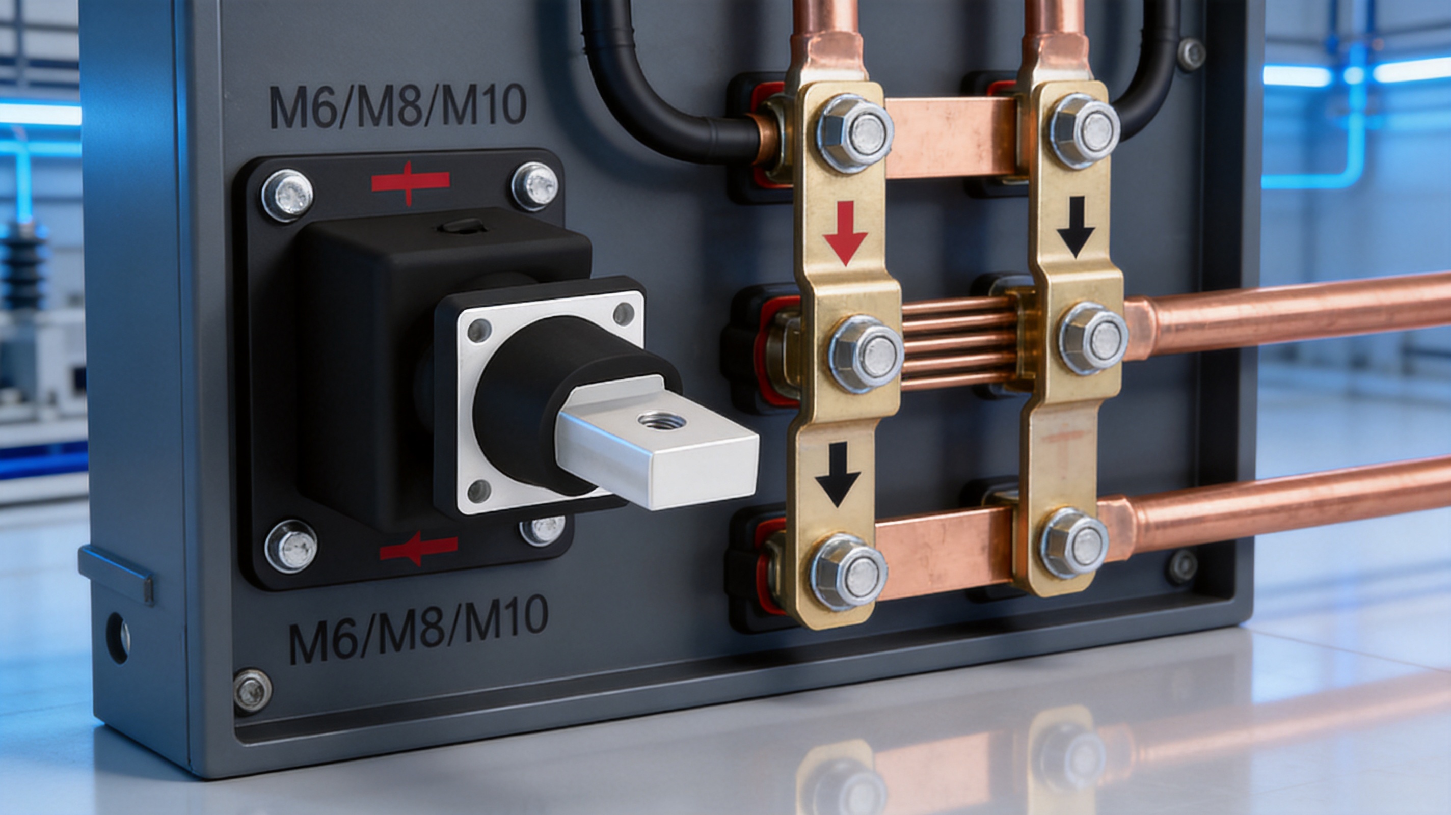
The core electrical interface is based on a screw or bolt connection. Depending on the model, the main terminal screw size may be M6, M8, or M10. The larger terminal options are suitable for higher-current versions and for conductors or busbars that require increased mechanical strength and contact area.
A bolted interface provides a clear installation method. The conductor or terminal lug is placed against the conductive connection surface and secured with the specified screw, nut, and appropriate tightening procedure. When installed correctly, the connection provides a stable current path and reduces the likelihood of accidental disconnection during vibration or equipment movement.
Connection quality depends on the complete installation process. The conductor must be correctly prepared, the contact surfaces must be clean, and the fastener must be tightened according to the equipment manufacturer’s instructions. The connector provides the engineered interface, while proper assembly ensures that the electrical and mechanical benefits are achieved in practice.
3. Electrical Performance and Available Ratings
The product family is designed to cover different power levels through multiple configurations. Published specifications include low-current options around 100 A and 120 A, medium-current options around 150 A and 200 A, and high-current options around 300 A, 350 A, and 400 A. Depending on the chosen model, the rated voltage is listed as 600 V DC, 1000 V DC, or 1500 V DC.
Because battery systems vary significantly in architecture, the correct model should be selected according to the actual continuous current, peak current, voltage, temperature, conductor type, installation arrangement, and applicable safety requirements. A connector with a nominal current rating should not automatically be used at that current in every environment. Thermal conditions, enclosure ventilation, cable size, contact resistance, duty cycle, and installation quality all influence real-world performance.
| Configuration Range | Typical Rated Current | Typical Rated Voltage | Dielectric Strength | Main Terminal Screw | Mounting Screw |
|---|---|---|---|---|---|
| Lower-current models | 100 A / 120 A | 600 V DC / 1000 V DC | 3000 V AC | M6 | M4 |
| Medium-current models | 150 A / 200 A | 600 V DC / 1500 V DC | 4000 V AC | M6 / M8 | M4 |
| High-current models | 300 A / 350 A / 400 A | 1500 V DC | 4000 V AC | M8 / M10 | M4 |
The values in the table represent the available specification ranges provided for the product family. Final performance depends on the exact model, conductor arrangement, thermal conditions, and installation method. For a complete product selection, the system designer should confirm the required rating with the technical documentation and application conditions.
High-Voltage Insulation
High-voltage battery systems require insulation that can withstand both normal operating voltage and temporary test stresses. The product information specifies rated voltage options up to 1500 V DC and dielectric strength testing up to 4000 V AC for selected configurations. This indicates that the connector is intended for demanding high-voltage environments rather than ordinary low-voltage wiring.
Dielectric strength is a test characteristic that evaluates the ability of an insulating system to withstand a higher applied voltage for a specified test period without breakdown. It should not be interpreted as a continuous operating voltage. The rated voltage identifies the intended normal operating range, while dielectric strength verifies an additional insulation margin under controlled test conditions.
The PA66 housing, the spacing around the conductive terminal, and the through-wall design work together to support insulation performance. These elements are particularly important in battery cabinets, where conductive parts may be installed close to metal enclosure panels, grounding structures, other terminals, and control components.
High-Current Connection Capability
High-current connections are sensitive to contact resistance. Even a small resistance can create significant heat when current increases. For example, the power loss caused by a connection is related to the square of the current multiplied by resistance. This means that maintaining a clean, stable, and sufficiently compressed conductive interface becomes increasingly important as current rises.
The use of a substantial H59 brass terminal and a bolted interface supports the requirements of high-current applications. The high-current models with M8 or M10 terminal screws are designed to accommodate the stronger mechanical and electrical demands associated with currents up to the 400 A range, subject to the specified model and installation conditions.
In practical system design, the connector should be paired with correctly sized cables, flexible links, copper busbars, or other conductors. The conductor must be able to carry the required current without excessive temperature rise, and the connection surface should match the terminal geometry to ensure even pressure and effective current transfer.
4. Advantages Compared with General-Purpose Connectors
General-purpose connectors may be suitable for control circuits, low-voltage wiring, or moderate-current applications, but they are not automatically appropriate for high-voltage battery systems. Battery and energy storage equipment creates a combination of electrical, thermal, mechanical, and safety requirements that ordinary connectors may not address.
Designed for High-Voltage Battery Environments
The Bolt Connector is specifically positioned for high-voltage battery and energy storage applications. Its voltage range, insulation structure, and through-wall format are aligned with the needs of high-voltage boxes, battery racks, and energy storage cabinets. This specialized design reduces the need to adapt general-purpose components for high-energy equipment.
Secure Mechanical Fixation
A bolt connection provides a firm mechanical interface that is familiar to electrical assembly technicians. Compared with a simple push-fit arrangement, a properly tightened bolt can offer greater resistance to accidental separation and movement. This is valuable in equipment exposed to vibration, transportation, thermal cycling, or repeated service operations.
Improved Installation Organization
The wall-mounted structure creates a defined route through the equipment enclosure. Instead of allowing high-voltage conductors to pass through improvised openings, the connector provides a dedicated panel interface. This can improve cabinet organization, support more consistent wiring layouts, and simplify inspection during production or maintenance.
Multiple Current and Voltage Options
The available models cover lower, medium, and high-current requirements. A system designer can select a 100 A or 120 A version for a lower-power circuit, a 150 A or 200 A version for an intermediate application, or a 300 A to 400 A version for a high-current battery or energy storage connection. This range is more flexible than a single fixed-rating connector.
Positive and Negative Pole Identification
The product information indicates that positive and negative pole color recognition is available to help prevent wiring errors. Polarity identification is an important practical feature in direct-current systems. Incorrect polarity can damage equipment, create hazardous fault conditions, or require extensive rework. Clear color differentiation supports more efficient assembly and inspection.
Flexible Wiring Orientation
The product is described as supporting wiring at any angle of 360 degrees. This feature can be useful when a cabinet layout requires cables to approach from different directions. Flexible orientation may simplify routing around battery modules, busbars, cooling components, protective barriers, and other internal equipment.
5. Manufacturing Strengths and Engineering Capabilities
Zhejiang Zhongyan New Energy Co., Ltd. specializes in new energy conductive components and precision electrical connection products. Its product scope includes high-voltage copper foil soft connections, special-shaped soft connections, battery soft connections, and related components for energy storage, electric vehicles, rail transit, communication, and power transmission and distribution.
The company was established in 2022 and has developed capabilities covering product design, research and development, precision manufacturing, testing, and application support. Its engineering team works with conductive materials, insulation components, joining technologies, and battery connection systems. This background is relevant to the development of high-voltage bolt connectors because connector performance depends on the coordinated design of the conductor, housing, fastening system, and installation interface.
Material and Component Engineering
Material selection is an important part of high-voltage connector development. The conductive material must offer suitable conductivity and mechanical strength, while the insulating material must maintain dimensional stability and electrical separation. The use of nickel-plated H59 brass for the conductor and flame-retardant PA66 for the housing reflects an approach that considers both electrical and mechanical requirements.
Material engineering also supports consistency between production batches. When the composition, surface treatment, and dimensions of a conductor are controlled, the manufacturer can work toward more stable contact resistance, thread quality, terminal geometry, and installation behavior. Likewise, controlled molding of the insulating housing helps maintain repeatable fit and insulation distances.
Polymer Diffusion Welding and Laser Technology
The company has independently developed polymer diffusion welding and laser technology patents for new energy precision components. These technologies are especially relevant to the broader product portfolio, including battery soft connections and copper foil connection assemblies. They demonstrate experience in joining conductive and insulating materials with high precision.
Although a bolt connector uses a mechanical fastening method for its main electrical connection, experience with diffusion welding and laser processing can strengthen the manufacturer’s overall understanding of heat input, material behavior, dimensional control, and connection reliability. These capabilities are valuable when designing complete battery connection systems in which bolt connectors may work alongside laminated busbars, flexible copper links, terminal plates, or cell contact systems.
Precision Manufacturing
Precision manufacturing is essential for a connector that must fit a panel, accept a specified fastener, maintain insulation distances, and provide a consistent conductive interface. The production process may include metal cutting or forming, machining, plating, plastic molding, assembly, dimensional inspection, and electrical testing.
Accurate metal processing helps ensure that the terminal is properly aligned and that the screw or bolt engages smoothly. Controlled nickel plating supports a consistent protective surface. Precision molding helps ensure that the PA66 housing fits the terminal correctly and that mounting features align with the enclosure opening.
Manufacturing consistency is especially important for original equipment manufacturers and system integrators. A connector used across a large number of battery cabinets must have repeatable dimensions and performance so that automated or semi-automated assembly processes can operate reliably.
Quality Management and Verification
The company reports the use of modern production and quality management systems. For high-voltage connectors, quality management should include incoming material inspection, process control, dimensional checks, terminal and plating verification, assembly inspection, and electrical testing.
Important verification activities may include insulation resistance testing, dielectric withstand testing, terminal continuity testing, dimensional inspection, mounting-fit verification, and visual examination of the housing and conductive surfaces. Depending on the target market, additional evaluation may be required for vibration, temperature cycling, humidity, salt exposure, mechanical endurance, and flammability.
Testing should be conducted using procedures appropriate to the exact product configuration and intended application. The stated dielectric strength and voltage ratings provide useful reference points, but equipment manufacturers should also evaluate the connector as part of the complete battery or energy storage assembly.
6. Applications in Battery and Energy Storage Equipment
High-Voltage Battery Packs
Battery packs for electric vehicles, industrial vehicles, and specialized mobile equipment require secure connections between modules and high-voltage distribution components. The Bolt Connector can serve as a through-wall interface between the battery enclosure and an external high-voltage harness. Its insulated housing helps separate the energized terminal from the metal structure of the enclosure.
In a battery pack, installation space is often limited. The 360-degree wiring orientation can help designers route cables according to the available space while avoiding sharp bends and unnecessary conductor stress. The connector can also support clearer separation between positive and negative circuits when color identification is used consistently.
Energy Storage Systems
Residential, commercial, and industrial energy storage systems use battery racks or cabinets connected to power conversion equipment. These systems often require high-current paths between battery modules, busbars, fuses, contactors, disconnect devices, and inverters. The Bolt Connector can be used as a cabinet wall interface for these high-voltage paths.
The 1500 V DC versions are suitable for system architectures that operate at elevated DC voltage, subject to the final design and relevant certification requirements. Higher system voltage can reduce current for a given power level, but it also increases insulation and safety requirements. A dedicated high-voltage connector helps system designers manage this interface in a controlled way.
High-Voltage Boxes
High-voltage boxes integrate important battery protection and distribution components, including contactors, fuses, pre-charge circuits, current sensors, and service disconnects. The box must provide safe transitions between internal components and external cables. A wall-mounted bolt connector creates a defined penetration point that can support a cleaner, more maintainable layout.
The square through-wall structure is particularly suitable for high-voltage boxes because it can be integrated into a flat panel. The mounting screws secure the connector to the box wall, while the insulated body separates the conductive terminal from the enclosure.
Industrial and Commercial Energy Storage Cabinets
Industrial and commercial storage cabinets may be installed in factories, data centers, commercial buildings, renewable energy facilities, or microgrids. These systems may experience high operating currents, regular maintenance activity, and demanding environmental conditions. Mechanical stability and clear polarity identification are therefore important.
The connector range allows cabinet manufacturers to select different current ratings for battery input, DC bus, auxiliary distribution, or parallel cabinet connections. A standardized connector family can also simplify spare-parts management and support common assembly procedures across multiple cabinet models.
New Energy Vehicle Wiring Harnesses
Electric vehicles and hybrid vehicles use high-voltage wiring harnesses to connect battery packs, inverters, onboard chargers, DC-DC converters, electric compressors, and other power components. A high-voltage through-wall connector can support the transition from an enclosed battery or power unit to an external harness.
Vehicle applications place strong demands on vibration resistance, compact packaging, temperature management, and assembly consistency. The final selection should be based on the specific vehicle environment, including vibration levels, thermal exposure, sealing requirements, ingress protection, and applicable automotive standards.
7. Installation and Application Considerations
Panel Preparation
The equipment panel should be prepared according to the connector’s approved dimensional drawing. The opening must provide adequate clearance for the body while allowing the mounting screws to engage correctly. Burrs, sharp edges, metal particles, and paint contamination should be removed before installation.
The connector should be installed on a structurally stable panel. If the enclosure wall is too thin or flexible, additional reinforcement may be necessary to prevent movement during cable installation or service. The panel should also provide sufficient space for the required bend radius of the connected cable or busbar.
Terminal Preparation
The conductor or cable lug must match the selected terminal screw size and contact surface. Cable strands should not be damaged during stripping or crimping. If a lug is used, the crimp should be made with an approved tool and inspected for complete compression.
Contact surfaces should be clean and free from grease, dirt, loose oxide, or metal chips. Any coating or surface treatment must be compatible with the connector and the installation instructions. Poor surface preparation can increase resistance and create localized heating.
Fastener Tightening
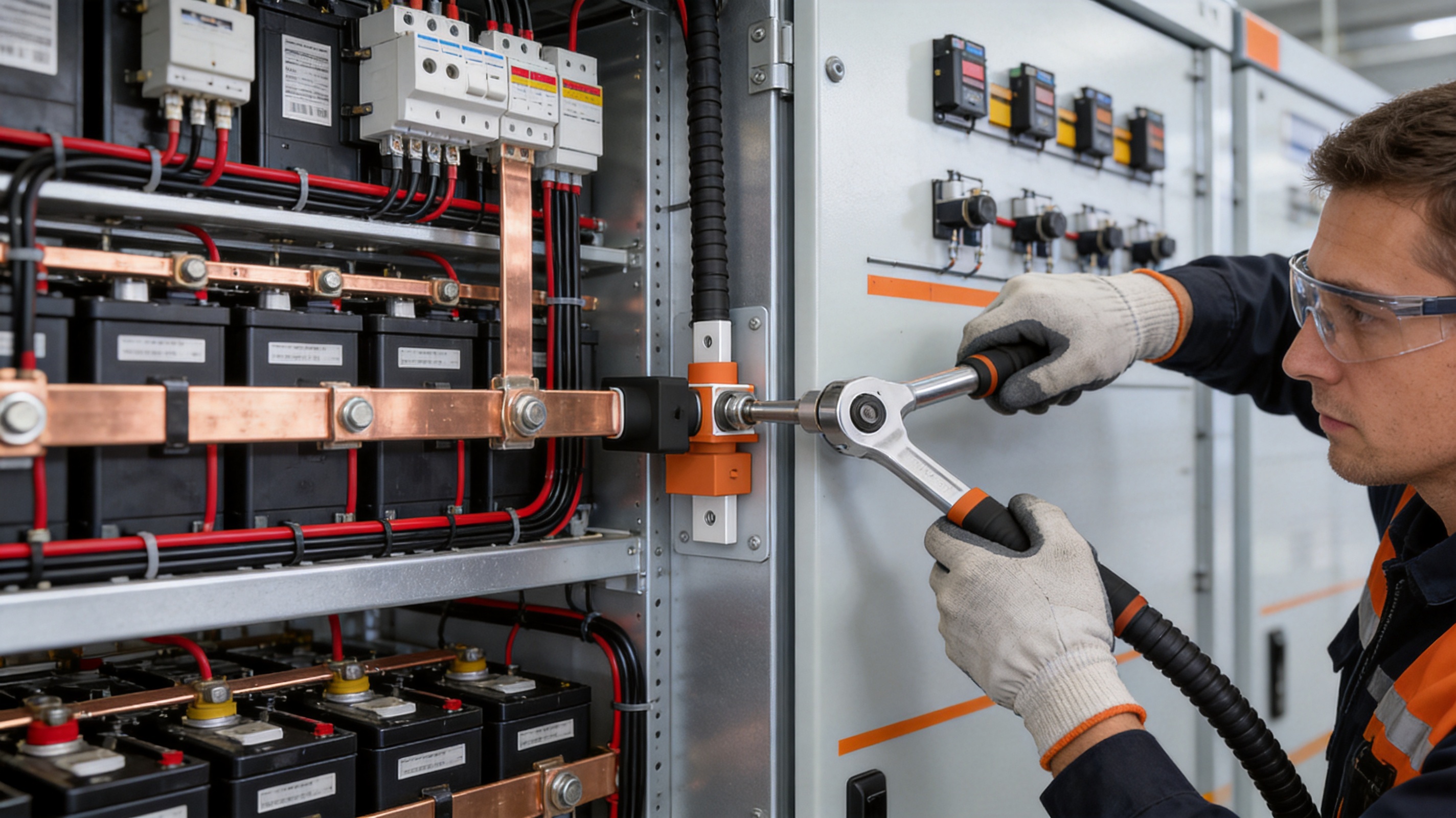
The main terminal screw should be tightened to the specified torque for the exact model and conductor arrangement. Under-tightening may cause insufficient contact pressure, while over-tightening may damage the terminal, screw, conductor lug, or housing. A calibrated torque tool is recommended for production and service work.
Mounting screws should also be tightened evenly so that the housing remains properly aligned against the panel. Uneven mounting pressure can place unnecessary stress on the plastic body or create gaps around the panel interface.
Polarity and Inspection
Before energizing the system, technicians should verify positive and negative polarity, terminal identification, cable routing, fastener tightness, insulation condition, and clearance from grounded metal parts. Color recognition can assist the process, but it should be combined with electrical verification and documented inspection procedures.
The completed connection should be checked for mechanical movement and signs of conductor stress. Cables should be supported independently where necessary so that their weight or vibration does not load the connector terminal. The connector is intended to provide an electrical interface, not to function as the sole support for heavy or unsupported cables.

8. Reliability, Safety, and Maintenance Benefits
Reliability in a high-voltage battery system depends on many factors, including cell quality, busbar design, protection circuitry, thermal management, enclosure construction, and connection integrity. The Bolt Connector contributes to this reliability by providing a dedicated, insulated, and mechanically secure connection point.
The use of nickel-plated brass helps protect the conductive interface, while the PA66 V-0 housing provides flame-retardant insulation. The through-wall structure reduces the need for improvised cable passages, and the bolt connection allows visual and mechanical inspection during maintenance.
Maintenance technicians can check the terminal for signs of discoloration, corrosion, looseness, contamination, or heat damage. If a connection has been subjected to abnormal current, short-circuit stress, water ingress, or mechanical impact, it should be inspected according to the system maintenance procedure. Any damaged connector, terminal, housing, or fastener should be replaced rather than returned to service without evaluation.
Color-coded polarity identification can help shorten inspection time and reduce the risk of reversing high-voltage DC connections. However, safe maintenance also requires appropriate lockout and isolation procedures. The connector should never be serviced while the battery system is energized or capable of delivering hazardous voltage.
9. Customization and OEM Support
Battery equipment manufacturers often require more than a standard catalog component. They may need a specific terminal size, mounting pattern, housing color, polarity marking, cable approach, current rating, or packaging method. A manufacturer with experience in conductive components and battery connection systems can support customization more effectively than a supplier focused only on general electrical hardware.
The product family already includes several current, voltage, terminal, and insulation-strength combinations. This provides a starting point for OEM projects. Custom development may involve adapting the mounting geometry, confirming conductor compatibility, optimizing the terminal interface, adjusting markings, or coordinating the connector with a battery pack’s busbar and harness design.
Engineering collaboration should begin with a complete application specification. Important information includes continuous and peak current, operating voltage, short-circuit conditions, ambient temperature, enclosure material, panel thickness, conductor type, available installation space, required protection level, expected vibration, service frequency, and applicable certification requirements.
The company’s broader capabilities in soft connections, special-shaped conductors, battery components, laser processing, and polymer joining can support integrated connection projects. For customers developing a complete battery module or energy storage cabinet, this may make it possible to coordinate the bolt connector with flexible copper connections, laminated busbars, cell contact systems, and other conductive components.
10. Why Choose a Specialized Manufacturer
A high-voltage connector is a safety-related component. Its performance depends not only on the nominal current rating but also on material selection, terminal geometry, insulation design, production accuracy, plating quality, assembly control, and verification. Working with a specialized manufacturer can help customers address these factors as part of a coordinated engineering process.
Zhejiang Zhongyan New Energy Co., Ltd. focuses on new energy conductive components and has experience serving power transmission, electric vehicle, rail transit, communication, and energy storage applications. The company has developed a technical team and production capability covering design, development, manufacturing, testing, and solution support.
Its experience with leading energy and automotive customers, including BYD, CATL, and Jaguar, reflects participation in demanding new energy supply chains. Such experience can help strengthen process discipline, documentation, quality consistency, and response to OEM requirements. Customers should still evaluate each product against their own technical specifications and required approvals.
The company is also expanding its capabilities in battery cells and connection systems. This direction supports a more integrated understanding of the relationship between cells, module-level conductors, battery management structures, high-voltage distribution, and external connections. For system developers, a supplier with knowledge of the complete connection chain may provide more useful technical coordination than a supplier offering an isolated component.
11. Product Selection Guide
Selecting the Current Rating
Begin by determining the continuous current and maximum expected current for the connection. Consider normal operation, charging, discharging, overload, peak power, thermal conditions, and duty cycle. The selected connector should provide adequate margin for the intended application without relying on theoretical conditions that cannot be maintained in the actual enclosure.
Selecting the Voltage Rating
Confirm the highest normal DC voltage, possible voltage transients, and the system’s insulation coordination requirements. Options include models rated at 600 V DC, 1000 V DC, and 1500 V DC. The rating should be selected according to the complete system, including pollution level, clearance, creepage, enclosure arrangement, and regulatory requirements.
Selecting the Terminal Screw
Choose M6, M8, or M10 based on current, conductor size, mechanical load, and available installation space. A larger screw is not automatically better if the conductor, lug, panel, or enclosure cannot accommodate it. The connection should be designed as a complete mechanical and electrical assembly.
Confirming Environmental Conditions
Evaluate ambient temperature, humidity, dust, vibration, chemical exposure, water exposure, and altitude. The connector’s PA66 housing and nickel-plated terminal provide a foundation for demanding applications, but the final protection level depends on the enclosure, seals, cable routing, and installation environment.
Checking System Compatibility
Confirm that the connector is compatible with the selected cable, busbar, terminal lug, fuse, contactor, service disconnect, and enclosure. Mechanical interference should be checked in a three-dimensional layout before production tooling or cabinet fabrication begins.
12. Frequently Asked Questions
What is the Bolt Connector used for?
It is used as a high-voltage, high-current through-wall connection for battery packs, energy storage systems, high-voltage boxes, industrial and commercial energy storage cabinets, and new energy vehicle wiring harnesses.
What current ratings are available?
The product family includes configurations in the approximate range of 100 A to 400 A. Listed options include 100 A, 120 A, 150 A, 200 A, 300 A, 350 A, and 400 A, depending on the specific model.
What voltage ratings are available?
Available specifications include 600 V DC, 1000 V DC, and 1500 V DC versions. The exact rating depends on the selected product configuration.
What material is used for the conductive terminal?
The conductor is made from H59 brass with nickel plating. This combination is selected for conductivity, mechanical strength, machinability, and surface protection.
What material is used for the insulating housing?
The housing uses PA66 plastic with a UL94 V-0 flame-retardant grade. It provides insulation and mechanical support around the conductive terminal.
Which terminal screw sizes are available?
The listed main terminal screw sizes include M6, M8, and M10. The correct size depends on the current rating and model.
What size are the mounting screws?
The product information specifies M4 mounting screws for the panel installation interface.
Can the connector be wired from different directions?
The product is designed to support wiring at any angle of 360 degrees. This can help simplify cable routing in compact battery and cabinet layouts.
How does the connector help prevent polarity mistakes?
Positive and negative pole color recognition is available to support visual identification. Polarity should still be confirmed through documented assembly checks and electrical testing before the system is energized.
Is the connector suitable for a 1500 V DC system?
Selected high-current models are specified at 1500 V DC. Suitability must be confirmed against the exact model, system insulation design, operating environment, and applicable safety requirements.
What dielectric strength is specified?
Depending on the model, the stated dielectric strength is 3000 V AC or 4000 V AC. This is a test value and should not be treated as the normal operating voltage.
Can the connector be customized for OEM projects?
OEM support can be discussed based on current, voltage, terminal size, mounting arrangement, conductor type, marking, enclosure design, and other application requirements. The manufacturer’s broader experience with battery connection systems can support coordinated product development.
What should be checked during installation?
Technicians should check panel dimensions, housing alignment, terminal cleanliness, conductor preparation, polarity, fastener torque, cable support, insulation clearance, and mechanical stability. The system must be isolated and de-energized before installation or maintenance.
Can the connector replace a fuse, contactor, or disconnect device?
No. The Bolt Connector provides an electrical and mechanical connection point. It does not replace protective devices, switching equipment, current sensors, battery management systems, or service disconnects.
13. Conclusion
The Bolt Connector is engineered for the demanding connection requirements of high-voltage batteries and energy storage systems. Its through-wall square structure, bolt connection method, PA66 V-0 insulating housing, nickel-plated H59 brass conductor, and broad range of current and voltage configurations make it suitable for many battery and power-distribution applications.
Compared with ordinary low-voltage or general-purpose connectors, it provides a more specialized solution for high-current and high-voltage equipment. The secure bolted interface supports stable electrical contact, while the wall-mounted design improves enclosure organization and wiring control. Positive and negative pole identification, 360-degree wiring flexibility, and multiple terminal sizes further support efficient installation.
The product is backed by a manufacturer focused on new energy conductive components, battery soft connections, precision connection systems, and related technologies. Its capabilities in material engineering, polymer diffusion welding, laser processing, precision manufacturing, testing, and quality management provide a foundation for both standard supply and OEM development.
For battery pack manufacturers, energy storage integrators, high-voltage box producers, and new energy vehicle suppliers, the connector can serve as a reliable interface between internal power assemblies and external high-voltage harnesses. Correct model selection, proper installation, appropriate conductor sizing, and complete system-level verification remain essential to achieving safe and dependable performance.
References
1. Product technical information for the Bolt Connector and LSP-series wall-mounted high-voltage connectors.
2. UL 94, Tests for Flammability of Plastic Materials for Parts in Devices and Appliances.
3. IEC 60664-1, Insulation Coordination for Equipment Within Low-Voltage Systems.
4. IEC 62477-1, Safety Requirements for Power Electronic Converter Systems and Equipment.
5. IEC 60900, Live Working—Hand Tools for Use Up to 1000 V AC and 1500 V DC.
6. General engineering practices for high-voltage battery packs, energy storage cabinets, and DC power distribution systems.
Product: Bolt Connector

Driven by the development of new energy and aiming for "zero carbon".
Copyright © Zhejiang Zhongyan New Energy Co., Ltd. All Rights Reserved.
