 English
 Español

Inverter Composite Laminated Busbar: High-Performance Power Distribution for Modern Energy Systems
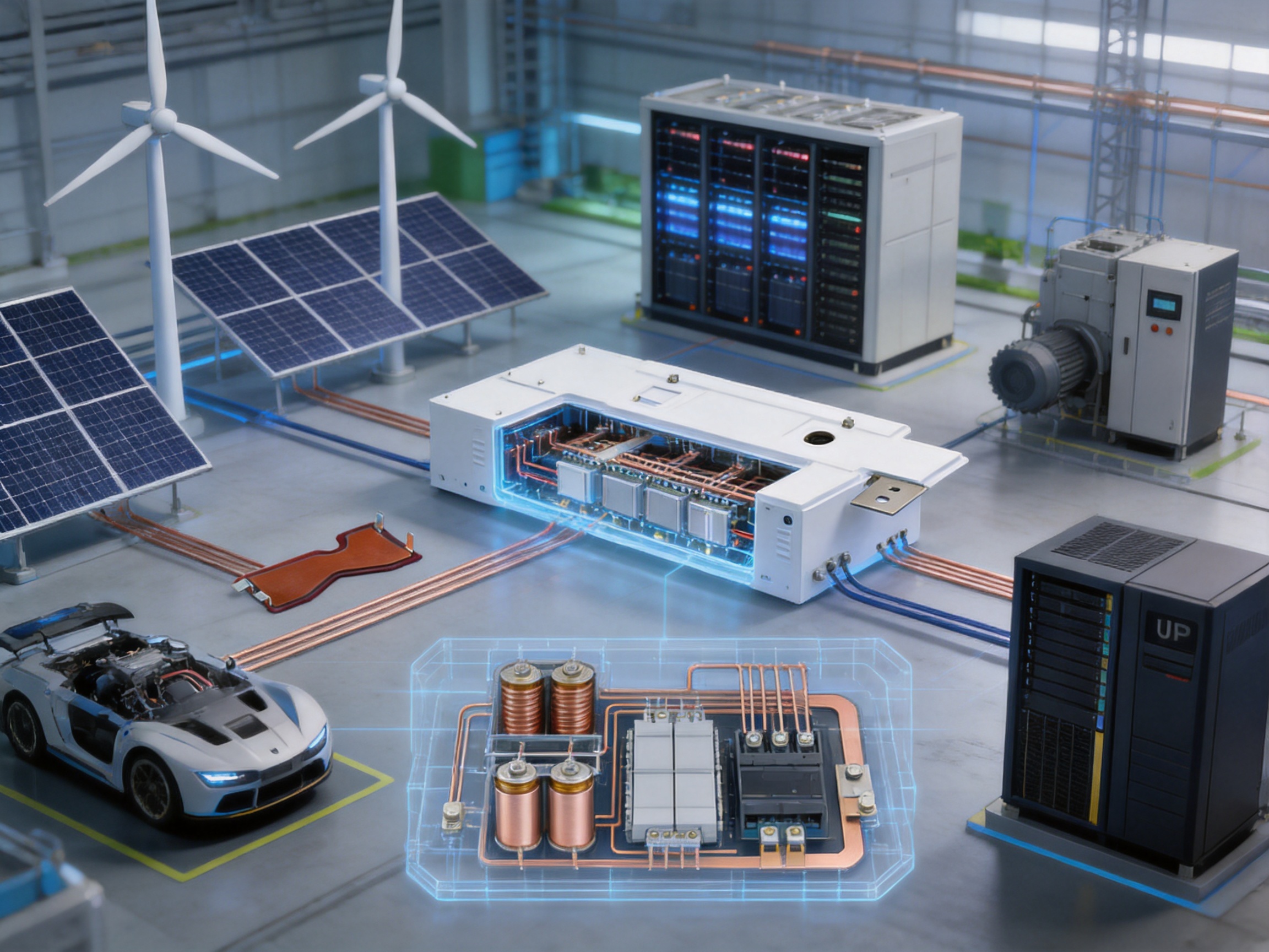
Modern power-conversion equipment must handle increasingly high voltages, high currents, compact installation spaces, rapid switching frequencies, and demanding safety requirements. Inverters used in renewable energy, energy storage, electric transportation, industrial automation, and uninterruptible power supplies are especially dependent on reliable internal power distribution. The busbar is not simply a metal conductor inside the enclosure. Its geometry, insulation system, plating, dielectric performance, thermal behavior, and manufacturing accuracy directly influence the safety, efficiency, service life, and maintainability of the complete electrical system.
The inverter composite laminated busbar is designed to address these requirements through a multilayer structure that integrates conductive copper plates with insulating materials into a compact, engineered assembly. Compared with conventional cable assemblies or separated solid busbars, a laminated busbar can reduce loop inductance, improve electrical consistency, simplify installation, and provide more controlled insulation performance. It is particularly suitable for high-power converters, photovoltaic inverters, wind power converters, railway equipment, electric propulsion systems, UPS systems, industrial drives, and other applications in which stable power transmission is essential.
Zhejiang Zhongyan New Energy Co., Ltd. supplies customized conductive components and composite laminated busbar solutions for demanding electrical applications. The company combines engineering design, precision processing, surface treatment, insulation integration, testing, and quality management to produce busbars according to specific voltage, current, space, and connection requirements. Its broader expertise in copper soft connections, battery connection systems, new energy components, and precision conductive parts supports a practical understanding of high-current electrical systems.
What Is an Inverter Composite Laminated Busbar?
An inverter composite laminated busbar is a prefabricated electrical connection assembly generally made from two or more conductive metal layers separated and surrounded by insulating materials. Copper is commonly used as the primary conductor because of its high electrical conductivity, good thermal performance, mechanical strength, and compatibility with plating processes. Depending on the electrical and environmental requirements, the conductive layers may receive tin, nickel, silver, or another suitable surface treatment.
The laminated structure is engineered to connect power semiconductor modules, capacitors, reactors, filters, terminals, and other elements within an inverter or power-conversion cabinet. The busbar can incorporate mounting holes, slots, bends, connection tabs, countersinks, threaded features, and other customized details. Instead of requiring an installer to route multiple cables or assemble several independent conductors, the laminated busbar provides a defined and repeatable connection path.
In a conventional arrangement, positive, negative, and sometimes phase conductors may be installed as separate copper bars or flexible cables. The physical distance between these conductors can create larger current loops and greater parasitic inductance. A laminated structure places associated conductors closer together, allowing magnetic fields to partially cancel and reducing the effective loop area. This characteristic is important in high-speed switching circuits, where voltage overshoot, electromagnetic interference, and switching losses can affect system performance.
The term “composite” refers to the integration of different materials and functional layers. Conductive copper layers provide current transmission, insulation layers provide electrical separation, bonding materials maintain structural integrity, and surface treatments support corrosion resistance and connection reliability. The final product is therefore a coordinated electrical and mechanical component rather than a simple flat metal strip.
Why Laminated Busbars Are Important in Inverter Design
Inverters convert electrical energy between direct current and alternating current or modify voltage and current characteristics for a specific application. These operations involve power semiconductor devices such as insulated-gate bipolar transistors, metal-oxide-semiconductor field-effect transistors, silicon carbide devices, and other switching technologies. Modern devices can switch faster and operate at higher power densities than earlier generations, increasing the importance of the internal connection system.
When a switching current passes through a conductor with parasitic inductance, the rate of current change can generate an additional voltage. This voltage may appear as overshoot across the switching device and can contribute to electrical stress, ringing, electromagnetic interference, and additional losses. A carefully designed laminated busbar helps reduce the physical loop area and provides a more controlled current path. While the busbar cannot replace appropriate circuit design, snubber networks, gate control, or thermal management, it is an important part of a coordinated high-performance inverter architecture.
Laminated busbars also improve assembly consistency. Cable-based systems often require manual cutting, stripping, crimping, bending, routing, and fastening. Variations in cable length, terminal position, bend radius, and tightening conditions can make production more difficult and inspection less predictable. A custom laminated busbar arrives as a defined component with known dimensions and connection points, helping reduce assembly time and potential installation errors.
Space utilization is another major consideration. Renewable-energy inverters, battery energy-storage systems, traction converters, and industrial drives increasingly require high output power in smaller enclosures. A laminated busbar can be formed to follow the available three-dimensional space while maintaining the specified insulation distances. This can reduce the volume occupied by wiring and leave more room for cooling systems, control boards, protection devices, and service access.
Electrical insulation is integrated into the component rather than added only during final assembly. This allows the designer and manufacturer to control dielectric spacing, insulation thickness, edge coverage, and mounting geometry as part of the product design. The result can be a cleaner and more organized power section with fewer exposed conductive surfaces.
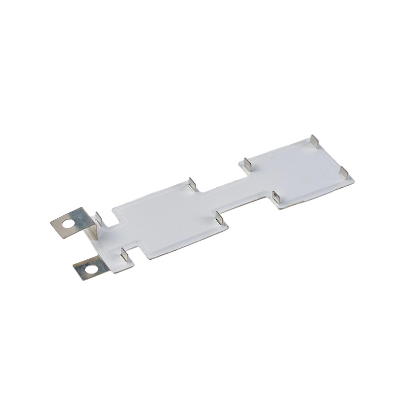
Inverter Composite Laminated Busbar
Key Product Advantages
Lower Parasitic Inductance
One of the primary advantages of a laminated busbar is the potential reduction of parasitic inductance. Conductive layers carrying opposing or related currents can be arranged in close proximity. The resulting magnetic-field interaction can reduce the effective loop inductance compared with widely separated cables or busbars.
Lower inductance is beneficial in high-frequency and high-speed switching applications. It may help reduce voltage spikes, ringing, electromagnetic radiation, and stress on power semiconductor devices. It can also support more stable operation of the DC link and improve the repeatability of the power path. The actual performance depends on the final geometry, material arrangement, current distribution, switching speed, and system design, so the busbar should be developed in cooperation with the electrical engineer responsible for the inverter.
High Current-Carrying Capability
Copper has excellent electrical conductivity and is widely used for high-current power distribution. The cross-sectional area, copper thickness, conductor width, connection design, and cooling conditions can be selected according to the required current. The product information includes examples ranging from 200 A to 1,200 A, demonstrating the range of applications that can be addressed through different designs.
High current is not determined by copper thickness alone. Thermal conditions, duty cycle, ambient temperature, enclosure ventilation, contact resistance, allowable temperature rise, and the distribution of current between layers must also be considered. A competent busbar manufacturer evaluates these factors during design and production rather than treating current capacity as an isolated specification.
Controlled Dielectric Performance
Inverter busbars often operate at hundreds or thousands of volts. The insulation system must prevent current leakage and unintended arcing between conductive layers, mounting structures, and adjacent components. The listed product examples specify a dielectric strength test of 5 kV DC for 60 seconds with leakage below 2 mA.
This test value represents a high-voltage withstand requirement used to verify insulation integrity under specified test conditions. The exact test voltage, duration, leakage limit, creepage distance, clearance distance, and insulation material should always be agreed upon according to the customer’s electrical standard and product application. A laminated busbar supplier should be able to document test procedures and provide inspection records when required.
Compact and Organized Construction
Custom geometry allows the busbar to match the enclosure, power module, capacitor bank, and terminal arrangement. Holes and slots can be positioned to align with the customer’s mechanical design, reducing the need for extra brackets or adapters. The result is an organized power section with clearly defined connection points.
Compact construction can also support shorter electrical paths. Shorter paths may reduce voltage drop and conductor material usage, although the result must be verified through electrical and thermal calculations. The laminated structure can combine several connections into one integrated component, helping simplify the bill of materials and reduce the number of individual parts used during assembly.
Improved Assembly Repeatability
A custom laminated busbar is produced according to controlled drawings and process requirements. Its dimensions, hole positions, conductor thickness, plating, insulation, and overall shape can be inspected before delivery. This supports repeatable installation across multiple inverter units.
Repeatability is especially valuable for high-volume manufacturing. It can reduce manual rework, improve takt time, and make production-line testing more consistent. It may also simplify field service because replacement parts can be designed to match the original installation points and connection sequence.
Reliable Surface Protection
Surface plating can improve the performance of copper interfaces. Tin plating is frequently selected because it provides practical solderability, contact compatibility, and protection against oxidation under suitable conditions. Other plating systems may be considered when the application requires specific conductivity, wear resistance, corrosion resistance, or environmental performance.
Surface treatment must be applied consistently. Variations in plating thickness, contamination, adhesion, or coverage can influence contact resistance and long-term reliability. For this reason, surface preparation, cleaning, plating control, and visual inspection are important parts of the manufacturing process.
Application-Specific Mechanical Design
The busbar may include perforated sections, mounting tabs, step features, angled bends, layered terminals, and other special shapes. The product examples include dimensions such as 453 mm × 221 mm, 480 mm × 316 mm, 420 mm × 147 mm, 237 mm × 225 mm, and 282 mm × 237 mm. These examples demonstrate that laminated busbars are not limited to one standard outline.
Thickness can also be adapted to the required current and mechanical structure. The provided examples include copper plate thicknesses of 2.0 mm, 2.5 mm, 3.0 mm, and 4.0 mm. The selection should consider current, temperature rise, stiffness, weight, available space, fastening conditions, and production feasibility.
Representative Technical Specifications
The following table summarizes representative configurations supplied in the product information. These values are examples rather than a universal specification for every laminated busbar. Final dimensions and ratings should be confirmed through an approved technical drawing and application review.
| Configuration | Overall Dimensions | Conductor Thickness | Surface Treatment | Voltage Rating | Current Rating | Dielectric Test |
|---|---|---|---|---|---|---|
| Option A | 453 mm × 221 mm | 2.5 mm perforated plate | Tin-plated | 1900 V DC | 200 A | 5 kV DC for 60 seconds, <2 mA |
| Option B | 480 mm × 316 mm | 2.0 mm copper plate | Surface-plated | 600 V DC | 1200 A | 5 kV DC for 60 seconds, <2 mA |
| Option C | 480 mm × 316 mm | 3.0 mm copper plate | Tin-plated | 1200 V DC | 500 A | 5 kV DC for 60 seconds, <2 mA |
| Option D | 420 mm × 147 mm | 2.5 mm copper plate | Surface-plated | 1900 V DC | 400 A | 5 kV DC for 60 seconds, <2 mA |
| Option E | 237 mm × 225 mm | 3.0 mm copper plate | Surface-plated | 1900 V DC | 400 A | 5 kV DC for 60 seconds, <2 mA |
| Option F | 282 mm × 237 mm | 4.0 mm copper plate | Tin-plated | 600 V DC | 300 A | 5 kV DC for 60 seconds, <2 mA |
The table illustrates an important point: voltage and current ratings are not directly determined by one dimension. A comparatively thin conductor can support a high current when its width, cooling, duty cycle, and connection design are appropriate, while a thicker conductor may be selected for mechanical stiffness or a different voltage architecture. A complete technical assessment is therefore required before selecting a configuration.
Manufacturing Process for Composite Laminated Busbars
1. Application and Drawing Review
Manufacturing begins with a detailed review of the customer’s application. Engineers examine the working voltage, continuous and peak current, switching frequency, short-circuit requirements, ambient temperature, installation environment, insulation system, connection hardware, and expected service life.
Mechanical information is equally important. The supplier reviews the enclosure, power modules, capacitor positions, mounting points, keep-out zones, cable routes, cooling channels, and required maintenance access. Three-dimensional data can help identify interference risks before tooling or production begins.
The drawing review should also define tolerances, hole sizes, bend angles, surface treatment, insulation thickness, edge requirements, identification marks, and inspection points. Clear documentation at this stage reduces changes later in the production process.
2. Copper Material Selection and Preparation
High-conductivity copper is selected according to the required electrical, mechanical, and manufacturing properties. Material certificates may be reviewed to verify grade, thickness, conductivity, and other relevant characteristics. Copper sheets or plates are then cut into blanks appropriate for stamping, laser cutting, CNC machining, or another approved process.
Material preparation must protect the copper surface from deep scratches, contamination, and deformation. Flatness is important because uneven material can affect insulation bonding, dimensional accuracy, and the final fit of the laminated assembly.
3. Precision Cutting and Forming
The copper conductor can be shaped through CNC machining, laser cutting, punching, stamping, milling, or a combination of methods. The selected method depends on the thickness, geometry, production volume, tolerance requirements, and presence of holes or slots.
Precision cutting creates the required outline and connection features. Forming operations may produce bends, offsets, steps, or three-dimensional profiles. Careful control is required to avoid cracks, burrs, sharp edges, or excessive deformation. Burrs and sharp corners can damage insulation or reduce creepage performance, so edge treatment is an important part of the process.
4. Deburring, Cleaning, and Surface Preparation
After cutting and forming, copper parts are deburred and cleaned. Deburring removes sharp edges and loose particles that could compromise insulation or create assembly hazards. Cleaning removes oils, oxides, dust, and residues that could interfere with bonding or plating.
Surface preparation must be appropriate for the selected insulation and plating processes. A clean, controlled surface promotes consistent adhesion and reduces the risk of hidden contamination inside the laminated structure. Depending on the process, cleaning may include mechanical treatment, chemical cleaning, degreasing, rinsing, and controlled drying.
5. Plating and Surface Treatment
The prepared copper parts may receive tin plating or another specified surface treatment. The purpose can include oxidation protection, improved contact performance, solderability, and compatibility with mating terminals. The treatment must cover the required surfaces without interfering with dimensional tolerances or insulation bonding areas.
Process control may include bath monitoring, current-density control, time management, rinsing, drying, thickness verification, and visual inspection. Plating quality is especially important at bolted interfaces, because surface condition and contact pressure influence contact resistance and heat generation.
6. Insulation Layer Preparation
Insulation layers are cut and shaped according to the conductor geometry. The insulation material must provide suitable dielectric strength, thermal endurance, dimensional stability, and resistance to the operating environment. The correct material depends on the voltage, temperature, humidity, chemical exposure, partial-discharge requirements, and mechanical design.
Insulation layers may include cut-outs for mounting points or terminals, but these openings must be designed carefully. Clearance and creepage distances must remain adequate after assembly. The edges of insulation around conductive features should be controlled to prevent local stress concentration and unwanted exposure.
7. Layer Alignment and Lamination
Conductive plates and insulation layers are stacked in a controlled sequence. Alignment fixtures help maintain the designed position of holes, edges, and terminals. Incorrect alignment can affect electrical spacing, mounting fit, and current distribution, so fixture accuracy and operator discipline are important.
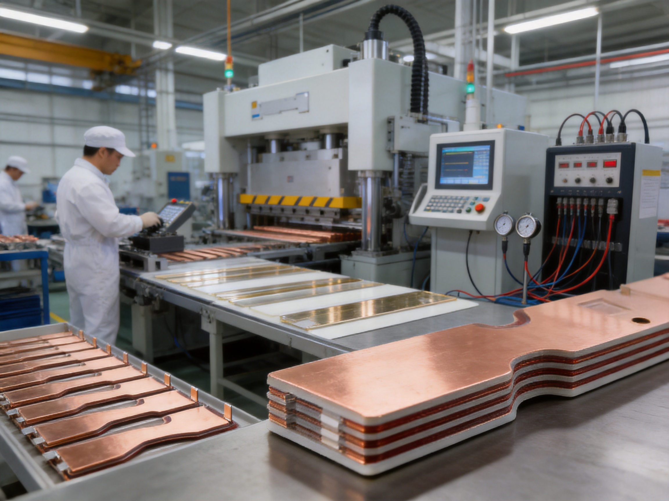
The layers are bonded or laminated under controlled pressure and temperature according to the selected material system. The process must provide consistent adhesion without creating voids, wrinkles, delamination, excessive resin flow, or distortion. Pressure and temperature profiles are monitored to ensure that the finished product meets the design requirements.
Composite lamination is one of the areas in which manufacturing capability strongly influences final quality. A busbar can have correct copper dimensions but still fail to perform reliably if the insulation contains voids, the bonding is incomplete, or the layers shift during processing. Proper tooling, process records, and trained personnel are therefore essential.
8. Finishing and Identification
After lamination, the assembly may undergo trimming, edge finishing, drilling, tapping, cleaning, and dimensional correction. Identification marks can be added for part number, revision, polarity, terminal location, or production traceability. Clear identification helps prevent installation errors during inverter assembly.
Any additional machining must be performed with care because it can expose conductive layers or reduce insulation distance. Post-processing is therefore controlled against the approved drawing and inspection plan.
9. Electrical and Mechanical Inspection
Inspection may include dimensional measurement, visual examination, plating verification, insulation inspection, hole-position measurement, flatness checking, and high-voltage dielectric testing. Depending on the customer’s requirements, additional tests may include insulation resistance, contact resistance, temperature-rise evaluation, partial-discharge testing, vibration testing, thermal cycling, humidity exposure, or mechanical load testing.
High-voltage testing is carried out under controlled safety conditions. The representative specifications state a dielectric strength test of 5 kV DC for 60 seconds with leakage below 2 mA. Test records can be associated with production batches or individual parts when traceability is required.
10. Packaging and Delivery
Laminated busbars should be packaged to prevent bending, abrasion, contamination, moisture exposure, and damage to plated surfaces. Protective films, separators, custom trays, or anti-static packaging may be used according to the product structure. Packaging design is particularly important for assemblies with large flat areas or protruding terminals.
Delivery documentation may include inspection reports, material certificates, test records, packing lists, and revision-controlled drawings. Reliable documentation helps customers integrate the product into their own quality systems.
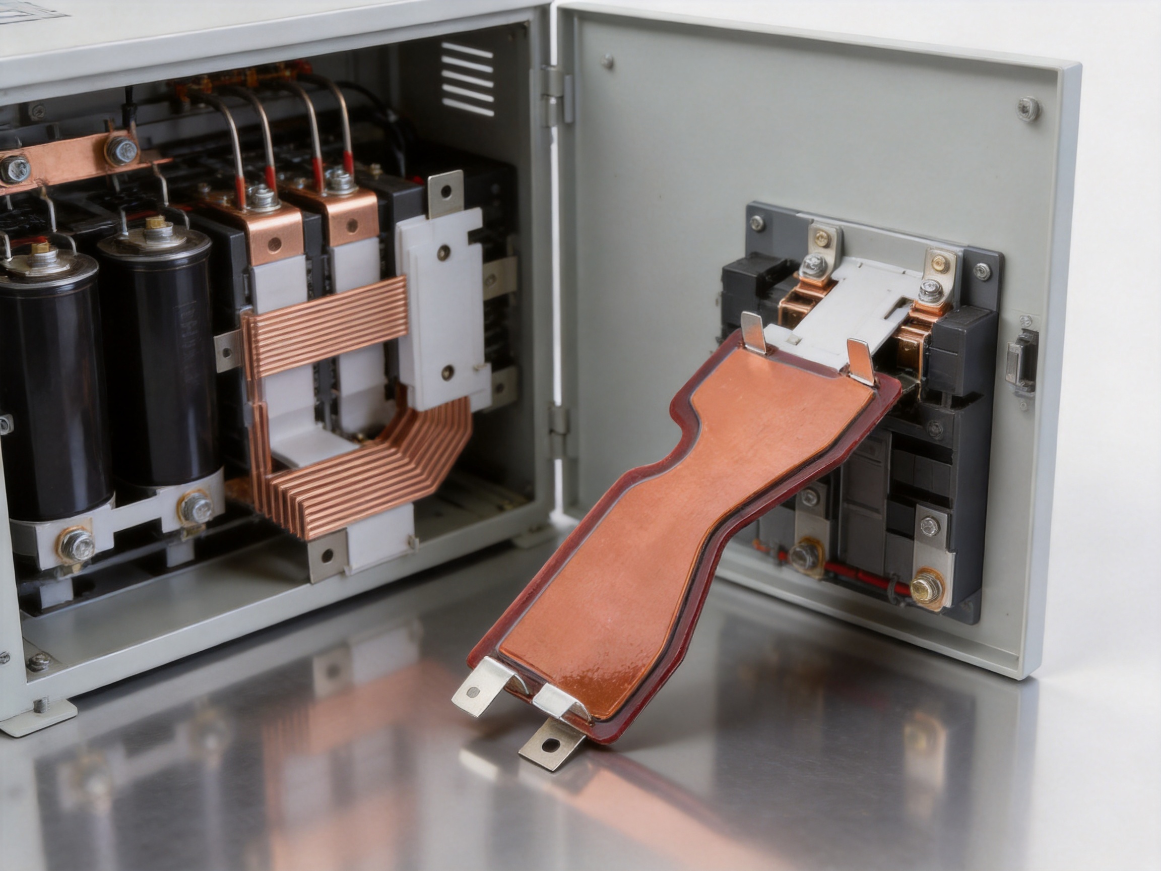
Manufacturing Strengths of Zhejiang Zhongyan New Energy
Zhejiang Zhongyan New Energy Co., Ltd. is a high-tech enterprise focused on new energy conductive components and precision electrical connection solutions. Its product scope includes high-voltage copper foil soft connections, special-shaped soft connections, battery soft connections, composite laminated busbars, battery connection systems, and related conductive components.
The company’s experience with battery and power-conversion connections supports a practical approach to busbar development. High-current connection products must balance conductivity, flexibility or stiffness, thermal behavior, insulation, mechanical integration, and production repeatability. These considerations are relevant across battery packs, energy-storage systems, electric vehicles, rail transportation, and inverter equipment.
The company brings together engineering personnel, technical teams, specialized production equipment, and quality-management procedures. This combination allows the product-development process to extend from initial concept and drawing review through manufacturing, testing, and delivery. Customers can work with one supplier for design adjustment, sample development, process verification, and production support.
Its experience in polymer diffusion welding and laser-related technologies is also relevant to the broader field of low-resistance electrical connections. While the manufacturing route for a composite laminated busbar depends on its specific structure, expertise in precision joining and conductive component production can help improve connection reliability and process control.
Established in 2022, the company continues to develop capabilities in battery cells, connection systems, energy-storage components, and integrated battery solutions. Its direction reflects the growing relationship between battery technology and power-conversion equipment. In practical applications, the inverter busbar, battery connector, cell contact system, and energy-storage connection architecture must work together as part of a complete electrical system.
Advantages Compared with Conventional Cable Assemblies
Cables remain useful for many electrical applications, especially where flexibility, long-distance routing, vibration isolation, or field adjustment is required. However, a laminated busbar can offer advantages when the connection path is short, high-current, space-constrained, and repeatable.
First, the laminated structure can reduce the number of separate parts. A cable assembly may require cables, lugs, heat-shrink tubing, clamps, supports, insulation barriers, and fastening hardware. A custom busbar can integrate several of these functions into one component.
Second, a busbar can provide more consistent geometry. Cable position may vary between assemblies, whereas the busbar follows a defined drawing. This is valuable when the electrical loop must remain compact or when the product is assembled automatically or semi-automatically.
Third, a laminated busbar can help manage insulation distances. With cables, spacing depends partly on routing and restraint. With a designed laminated structure, conductive layers and insulation barriers are created as part of the product.
Fourth, the busbar may reduce installation labor. A preformed assembly can be placed and fastened directly, reducing cutting, crimping, and routing operations. Fewer manual operations can improve consistency and reduce the possibility of incorrect cable orientation or terminal selection.
Finally, the mechanical structure can be more compact. This is useful in inverter cabinets, battery systems, railway converters, and industrial drives where available space is limited.
Advantages Compared with Separate Rigid Busbars
Separate rigid busbars can provide excellent current capacity, mechanical strength, and low resistance. However, they may require additional insulation barriers, spacers, mounting brackets, and careful manual alignment. Their physical arrangement may produce larger conductor spacing and a larger current loop.
A laminated busbar combines multiple layers into an integrated structure. The designer can place positive and negative conductors close together, maintain controlled insulation, and provide connection positions that match the rest of the assembly. This can simplify the overall architecture.
Another difference is production repeatability. Separate bars may need to be individually installed and adjusted, while a laminated busbar can be inspected as a finished assembly before it reaches the customer’s production line. This does not eliminate the need for proper installation, but it can reduce the number of variables in the final system.
The best choice depends on the application. A laminated busbar is especially attractive when the system requires compactness, controlled inductance, integrated insulation, and repeatable assembly. A conventional rigid bar may remain suitable for simple, low-frequency, open-frame, or highly adjustable installations.
Application Fields
Renewable-Energy Inverters
Wind power converters and high-power photovoltaic grid-connected converters require reliable high-current connections between DC sources, capacitors, switching modules, filters, and AC output sections. A laminated busbar can support compact internal layouts and controlled electrical paths within the converter cabinet.
Renewable-energy equipment often operates outdoors or in industrial environments where temperature variation, humidity, dust, vibration, and long service life must be considered. The insulation system, plating, sealing strategy, and enclosure design should therefore be evaluated together.
Energy-Storage Systems
Battery energy-storage systems require conductive components that connect cells, modules, contactors, fuses, DC links, and inverters. Laminated busbars can be used in power-conversion sections and, in some designs, as part of the internal connection architecture between battery modules and high-voltage equipment.
The busbar must be coordinated with the battery management system, protection devices, pre-charge circuit, current sensors, and service disconnects. Correct polarity identification and safe insulation design are especially important in high-voltage storage systems.
Electric and Hybrid Transportation
Electric buses, rail vehicles, marine propulsion systems, and heavy equipment use power converters to control traction motors and auxiliary systems. These applications may impose strict requirements on voltage, current, vibration, shock, thermal cycling, electromagnetic compatibility, and partial discharge.
A laminated busbar can provide a robust and organized connection within traction inverters and auxiliary converters. The final design must be validated against the relevant transportation standards and the specific mechanical and environmental conditions of the vehicle.
Industrial Drives and UPS Systems
Industrial motor drives, welding equipment, medical equipment, and uninterruptible power supplies depend on stable power distribution. In these systems, the busbar may connect rectifier sections, DC-link capacitors, switching devices, output terminals, and filters.
UPS systems in particular may operate continuously and may be expected to transfer load reliably during power disturbances. Low-resistance connections, controlled insulation, stable mounting, and thermal performance all contribute to system dependability.
Telecommunication and Data Infrastructure
Communication infrastructure, ADSL racks, switching systems, and data-storage servers require dependable power distribution in compact cabinets. Although the current level may vary widely by system, the need for organized wiring, serviceability, low loss, and controlled insulation remains important.
Aerospace and Defense Equipment
Aerospace and defense equipment can require lightweight, compact, vibration-resistant, and highly reliable electrical assemblies. Composite laminated busbars may be considered where their weight, geometry, dielectric performance, and current capacity meet the relevant program requirements. Such applications normally require specialized qualification, documentation, and traceability beyond standard commercial production.
Design Considerations for Selecting a Laminated Busbar
Voltage and Insulation Coordination
The rated voltage should be evaluated together with transient overvoltage, pollution degree, altitude, humidity, switching behavior, and required insulation category. Clearance is the shortest distance through air, while creepage is the shortest distance along an insulating surface. Both must be considered in the geometry.
High-voltage systems may also require partial-discharge evaluation, especially when voids, sharp edges, or complex insulation interfaces could produce localized electrical stress. The required test method should be specified during the design stage.
Continuous and Peak Current
The designer should provide both continuous and peak current values, along with duration and duty cycle. Short-duration overloads can produce significant heating even when the average current is moderate. The current distribution between parallel layers and the resistance of bolted or welded interfaces should also be evaluated.
Thermal Conditions
Temperature rise depends on conductor resistance, current, surface area, airflow, nearby heat sources, enclosure design, and connection resistance. Copper thickness and width should be selected with the complete thermal environment in mind. If the busbar is located near power modules or capacitors, heat transfer and insulation temperature limits must be reviewed.
Mechanical Loads
Busbars can be exposed to vibration, shock, electromagnetic forces during fault current, thermal expansion, and assembly loads. Mounting points should support the product without creating stress concentrations. The design should also avoid excessive force on power-module terminals or capacitor terminals.
Material and Plating
Copper grade and surface treatment should match the connection method and environmental conditions. Tin-plated surfaces are common, but another treatment may be preferable for certain high-temperature, high-cycle, or corrosion-sensitive applications. The mating terminal material and fastening method should be considered as part of the same connection system.
Manufacturing Tolerances
Very tight tolerances can increase production cost without improving system performance. Tolerances should therefore be defined according to functional requirements. Hole position, conductor spacing, insulation cut-outs, flatness, and terminal alignment are usually more important than unnecessary precision in non-functional areas.
Quality Assurance and Testing
A reliable laminated busbar requires quality assurance at multiple stages. Incoming material inspection confirms that copper, insulation, and plating-related materials meet the approved specifications. In-process inspection verifies cutting, forming, cleaning, alignment, lamination, and finishing. Final inspection verifies the completed assembly.
Dimensional inspection can be performed using calibrated measuring equipment, gauges, coordinate measurement systems, or inspection fixtures. Visual inspection checks for scratches, cracks, burrs, exposed conductors, contamination, incomplete bonding, plating defects, and surface damage.
Electrical testing is central to the product. Dielectric withstand testing verifies that the insulation system can tolerate the specified test voltage. Insulation resistance testing evaluates resistance between conductors and between conductors and accessible structures. Contact-resistance measurement may be used to verify the quality of terminals and joints.
For demanding projects, environmental and reliability testing may include temperature cycling, humidity exposure, vibration, mechanical shock, thermal aging, and current-carrying tests. The exact test plan should be based on the customer’s standards and risk assessment.
Traceability is another important quality factor. Production batches, material certificates, process parameters, inspection results, and test records can be retained to support later analysis and customer audits. A structured quality system helps identify the source of any nonconformance and supports continuous improvement.
Customization and OEM Support
Inverter composite laminated busbars are rarely one-size-fits-all components. Each inverter platform may have different capacitor spacing, semiconductor terminals, enclosure dimensions, cooling arrangements, voltage requirements, and service-access restrictions. Custom manufacturing is therefore essential for many applications.
OEM support may begin with a customer drawing, three-dimensional model, sample, hand sketch, or description of the electrical function. Engineers can review the information, identify manufacturing concerns, recommend suitable materials and processes, and prepare a production drawing for approval.
Prototype production allows the customer to verify fit, clearance, installation sequence, polarity, and interface compatibility. Electrical and mechanical testing can be performed before volume production. Design changes are more economical at the prototype stage than after tooling and mass production have been completed.
For repeated orders, revision control is critical. Changes to hole position, plating, insulation material, copper thickness, or lamination structure should be documented and approved. Consistent production depends on maintaining the correct revision and preventing unauthorized substitutions.
Installation and Handling Recommendations
Laminated busbars should be handled carefully to prevent bending, scratches, contamination, and damage to insulation edges. Products should remain in their protective packaging until they are ready for installation. If storage conditions are controlled, the risk of moisture absorption and surface contamination can be reduced.
During assembly, the busbar should be aligned without forcing it into position. Fasteners should be tightened according to the specified torque. Excessive torque can damage terminals, deform insulating layers, or place stress on connected components, while insufficient torque can increase contact resistance and heating.
Technicians should verify polarity, terminal identification, insulation clearance, washer arrangement, and the absence of foreign materials before energization. The completed assembly should be inspected for loose hardware, exposed conductors, damaged insulation, and interference with nearby parts.
If the inverter is subject to vibration or thermal cycling, the fastening and support strategy should be validated for the operating environment. The busbar should not be used as an unintended structural support for unrelated components unless this function has been included in the design.
Frequently Asked Questions
What is the main purpose of an inverter composite laminated busbar?
Its main purpose is to provide a compact, insulated, and reliable high-current connection between power-conversion components such as capacitors, semiconductor modules, terminals, filters, and DC-link sections. Its laminated structure can also help reduce parasitic inductance and improve assembly repeatability.
Can the busbar be customized for a specific inverter?
Yes. Dimensions, copper thickness, hole positions, bends, insulation structure, surface treatment, voltage requirements, current capacity, and mounting features can be developed according to an approved customer drawing and application specification.
What copper thicknesses are available?
The representative product information includes copper plate thicknesses of 2.0 mm, 2.5 mm, 3.0 mm, and 4.0 mm. Other thicknesses may be considered depending on current, mechanical, thermal, and manufacturing requirements.
What current range can the product support?
The listed examples include current ratings from 200 A to 1,200 A. The final current rating depends on conductor width and thickness, duty cycle, cooling conditions, allowable temperature rise, connection resistance, and the complete system design.
What dielectric test is specified for the examples?
The representative examples specify 5 kV DC for 60 seconds with leakage below 2 mA. The final test voltage and acceptance criteria must be confirmed according to the customer’s electrical standard and application requirements.
Why is tin plating used on a copper busbar?
Tin plating can help protect copper from oxidation and provide a practical surface for bolted or other electrical connections. It can also support solderability where relevant. The selected plating must match the mating material, environment, temperature, and connection method.
Is a laminated busbar better than a cable?
It can be advantageous when the application requires a compact, repeatable, high-current connection with controlled insulation and low loop inductance. Cables may remain preferable where flexibility, long routing distances, or frequent movement is required.
Can the busbar be used in battery energy-storage systems?
Yes. Laminated busbars can be used in power-conversion and battery connection architectures, provided that the voltage, current, insulation, thermal, mechanical, and safety requirements are properly evaluated.
What information should be provided when requesting a quotation?
Useful information includes the electrical schematic, working and transient voltage, continuous and peak current, dimensions, three-dimensional model or drawing, copper thickness, plating requirement, insulation specification, mounting method, environmental conditions, quantity, testing requirements, and applicable standards.
How does the manufacturer support prototype development?
The manufacturer can review customer drawings, assist with material and process selection, produce samples, perform dimensional and electrical inspection, and adjust the design before volume production. Prototype validation helps confirm fit, electrical spacing, installation, and manufacturing feasibility.
Conclusion
The inverter composite laminated busbar is a strategically important component for modern high-power electrical systems. By integrating copper conductors, insulation layers, mounting features, and surface treatment into one engineered assembly, it can provide a more compact and repeatable alternative to separate cables or rigid busbars. Its potential benefits include lower parasitic inductance, high current capacity, controlled dielectric performance, improved space utilization, reduced assembly labor, and more consistent production quality.
The product examples cover multiple physical sizes, copper thicknesses, voltage levels, and current ratings, including configurations from 200 A to 1,200 A and dielectric testing at 5 kV DC for 60 seconds with leakage below 2 mA. These examples demonstrate the flexibility of the product platform, while also emphasizing the importance of application-specific engineering.
Zhejiang Zhongyan New Energy Co., Ltd. combines precision conductive-component manufacturing, engineering development, surface treatment, insulation integration, electrical testing, and quality management to support customized busbar production. Its broader capabilities in battery soft connections, high-voltage copper foil connections, energy-storage components, and new energy systems provide a strong foundation for developing reliable connection solutions.
For renewable-energy converters, battery-storage systems, transportation equipment, industrial drives, UPS systems, communication infrastructure, and other high-performance applications, a well-designed laminated busbar can improve the organization and reliability of the power section. The best results are achieved when electrical, thermal, mechanical, insulation, and manufacturing requirements are considered together from the earliest design stage.
References
1. IEC 60664-1, Insulation Coordination for Equipment within Low-Voltage Systems: Principles, Requirements and Tests.
2. IEC 62477-1, Safety Requirements for Power Electronic Converter Systems and Equipment.
3. IEC 61287-1, Railway Applications—Power Converters Installed on Board Rolling Stock.
4. IEEE standards and technical guidance concerning power electronics, electromagnetic compatibility, insulation systems, and high-current interconnections.
5. Manufacturer technical data for custom copper conductors, laminated busbars, high-voltage connection systems, and power-conversion assemblies.
6. General engineering principles for copper conductivity, busbar temperature rise, electrical clearance, creepage distance, contact resistance, and dielectric withstand testing.
Product: Inverter Composite Laminated Busbar

Driven by the development of new energy and aiming for "zero carbon".
Copyright © Zhejiang Zhongyan New Energy Co., Ltd. All Rights Reserved.
