 English
 Español

Insulated Enameled Copper and Aluminum Motor Busbars for High-Performance Electrical Systems
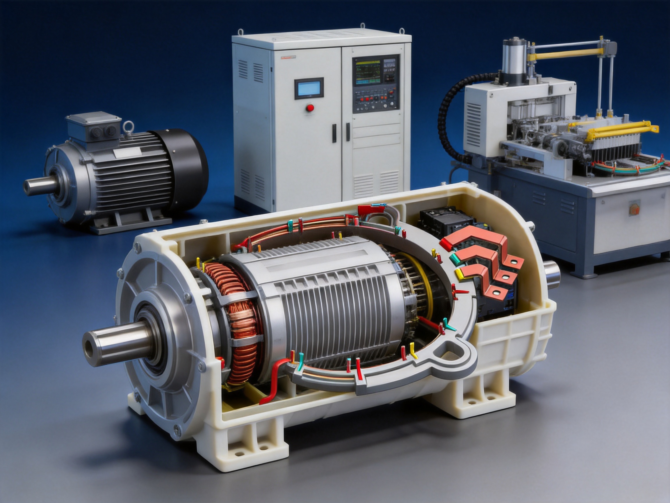
Modern motors and power systems require electrical connection components that combine high conductivity, dependable insulation, mechanical stability, and precise dimensional control. As motor designs become more compact and operating currents continue to increase, conventional cable assemblies and simple uninsulated conductors may no longer provide the required performance. An insulated enameled copper or aluminum motor busbar offers a carefully engineered alternative for transmitting current through electric motors, generators, power equipment, and other high-current assemblies.
These motor busbars are manufactured from high-quality copper or aluminum profiles and finished with an enamel insulation layer. Depending on the design, the conductive profile can be laser cut, stamped, bent, punched, tapped, or otherwise processed to match the customer’s drawing. Plastic injection molding can also be used to create fixing structures and integrated support features around the enameled conductor. This combination of metal processing, insulation technology, and precision molding allows complex electrical parts to be produced for demanding applications.
Zhejiang Zhongyan New Energy Co., Ltd. specializes in precision conductive components and new energy electrical connection solutions. Its manufacturing capabilities include copper and aluminum busbars, high-voltage flexible connections, battery soft connections, special-shaped conductors, and other precision parts for electric vehicles, energy storage, power distribution, communication, rail transit, and industrial equipment.
The insulated motor busbar described in this article is designed to provide reliable current transmission while reducing the risk of electrical contact, short circuits, insulation failure, and assembly inconsistency. Its customizable construction makes it suitable for electric vehicle motors, industrial motors, servo motors, generators, motor control systems, power tools, household appliances, and other equipment with demanding electrical and mechanical requirements.
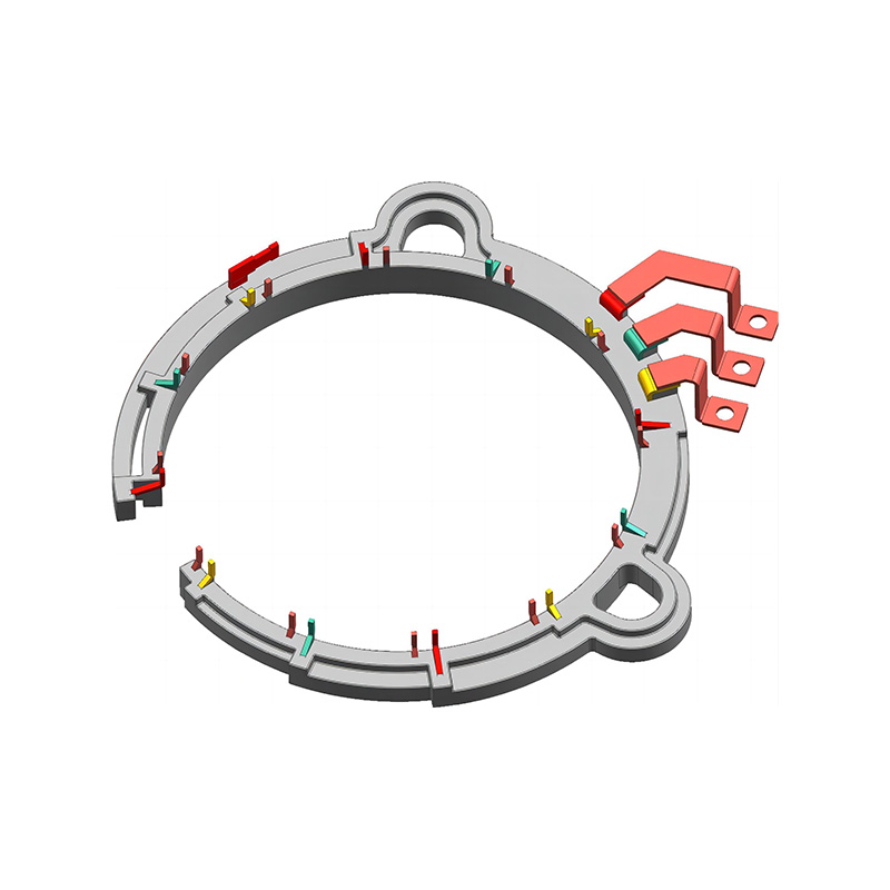
Insulated Enameled Copper & Aluminum Motor Busbar | Precision Metal Parts
Content
- What Is an Insulated Enameled Motor Busbar?
- Core Materials and Electrical Performance
- Advanced Manufacturing Process
- Key Advantages Compared with Conventional Busbar Solutions
- Technical Parameters
- Applications in Electric Vehicles and New Energy Motors
- Applications in Industrial and Servo Motors
- Applications in Generators and Power Equipment
- Applications in Tools, Appliances, and Automation
- Quality Control and Reliability Considerations
- Why Choose a Specialized Manufacturer?
- Customization Process for OEM Projects
- Design Guidance for Engineers
- Environmental and Compliance Considerations
- Comparison with Alternative Connection Methods
- Benefits for Production and Supply Chain Management
- Future Development of Motor Busbars
- Questions and Answers
- What is the main function of an insulated enameled motor busbar?
- Which materials are available?
- What insulation temperature classes are available?
- Can the busbar be manufactured according to a drawing?
- Can fixing parts be integrated into the busbar?
- What processing methods are available?
- Is aluminum suitable for motor busbars?
- Can copper busbars be used in electric vehicle motors?
- How does the product compare with flexible cable?
- What information should be provided for a quotation?
- Can the busbar support high-current applications?
- What industries can use these products?
- Conclusion
- References
- Product: Insulated Enameled Copper & Aluminum Motor Busbar | Precision Metal Parts
What Is an Insulated Enameled Motor Busbar?
An insulated enameled motor busbar is a shaped electrical conductor covered by a thin, durable enamel insulation layer. The conductor is generally manufactured from copper or aluminum. Copper is selected when maximum conductivity, compact dimensions, and high current density are priorities. Aluminum is often selected when weight reduction, cost efficiency, and lightweight motor construction are especially important.
Unlike a traditional bare busbar, an enameled busbar does not require the same level of external insulating barriers or spacing components in every application. The enamel coating creates an insulating surface around the conductive metal, allowing the busbar to be routed through a motor or electrical assembly while helping prevent unintended contact with adjacent conductive parts.
The busbar may have a straight, curved, stepped, U-shaped, L-shaped, or highly customized profile. Holes, slots, threaded sections, terminals, bends, and mounting features can be incorporated into the conductor according to the electrical and mechanical requirements of the finished product. For complex assemblies, injection-molded plastic fixing parts can be added to support positioning and installation.
This construction provides more than simple electrical conductivity. It creates a complete connection component that can be engineered around the available motor space, winding arrangement, terminal layout, cooling structure, and assembly sequence. As a result, the motor busbar becomes an integrated part of the equipment rather than a generic piece of metal that must be adapted during installation.
Core Materials and Electrical Performance
Copper Conductors
Copper is widely used in motor busbars because of its excellent electrical conductivity, thermal performance, and mechanical reliability. T2 copper and C11000 copper are commonly specified for applications requiring stable current transmission and low electrical resistance. Copper conductors can carry substantial current through a relatively compact cross-section, which is valuable in motors where internal space is limited.
A high-purity copper busbar also helps reduce heat generation caused by electrical resistance. Lower heat generation may support better motor efficiency and can reduce the burden on cooling systems. In high-current applications, these benefits can contribute to more stable operation, longer component life, and improved overall system reliability.
Copper also provides good compatibility with a wide range of connection methods. It can be laser cut, stamped, bent, drilled, punched, tapped, plated, and joined to other conductive components. Surface treatments such as tin plating, nickel plating, or silver plating may be selected when the application requires improved solderability, contact performance, corrosion resistance, or compatibility with specific connection environments.
Aluminum Conductors
Aluminum 1060 and 1070 are suitable choices for applications in which low weight is a primary design objective. Aluminum has a lower density than copper, making it possible to reduce the mass of motor connection components without eliminating the required conductive path. This can be especially valuable in electric vehicles, portable equipment, aerospace-related systems, and motors where reduced rotating or structural weight contributes to better efficiency.
Although aluminum has lower electrical conductivity than copper, an appropriately designed aluminum busbar can deliver reliable current performance through optimized cross-sectional dimensions and careful engineering. Aluminum also offers good corrosion resistance when the material, surface condition, insulation, and connection method are properly selected.
The choice between copper and aluminum depends on the application’s current requirements, available installation space, allowable weight, thermal conditions, joining method, and total cost objectives. A professional manufacturer can help evaluate these factors and recommend the most appropriate conductor material and profile.
Insulation Materials
The insulation layer is produced using enamel insulation technology associated with enameled wire and electrical winding applications. The coating creates a dielectric barrier around the metal conductor while maintaining a compact overall structure. This is important in motors because internal components are often closely arranged, and available clearance may be limited.
Insulation temperature classes can be selected according to the working environment. Common options include Class B at 130°C, Class F at 155°C, and Class H at 180°C. The appropriate choice depends on the motor’s normal operating temperature, overload conditions, thermal cycling, cooling system, and required service life.
The enamel layer is designed to provide dielectric strength, resistance to aging, and protection against corrosion-related deterioration. It can also help protect the conductor from environmental exposure during assembly and operation. For long-term reliability, the insulation specification should be matched with the motor’s voltage, temperature, vibration, humidity, and chemical conditions.
Advanced Manufacturing Process
Digital Production and Product Engineering
The manufacturing process begins with an evaluation of the customer’s design requirements. These may include electrical current, voltage, insulation class, conductor material, cross-sectional dimensions, bend locations, mounting features, hole patterns, terminal geometry, and installation clearances. Customer drawings, three-dimensional models, or technical specifications can be used as the basis for product development.
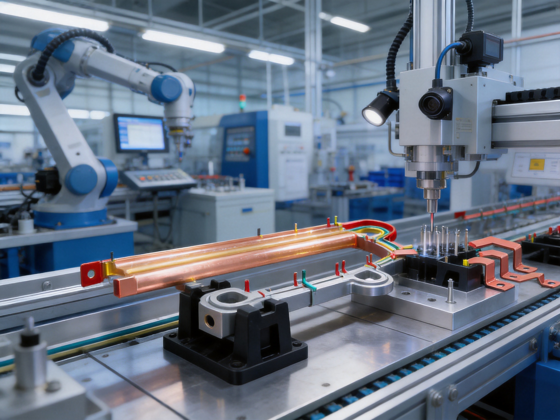
Digital production systems allow the manufacturer to convert product designs into controlled manufacturing data. This helps maintain consistency between the approved drawing, production tooling, process parameters, inspection requirements, and final product. Digital control is particularly valuable when the busbar has multiple bends, irregular openings, complex fixing structures, or tight dimensional tolerances.
Before mass production, the design can be reviewed for manufacturability. Engineers may assess bend radii, punching locations, edge conditions, coating areas, plastic fixing positions, and the sequence of metal processing. This approach can identify potential interference or assembly difficulties before the product reaches the customer’s production line.
Metal Profile Preparation
The selected copper or aluminum material is prepared in accordance with the required width, thickness, length, and cross-sectional profile. The specified ranges may include thicknesses from 1 mm to 15 mm, widths from 5 mm to 200 mm, and custom lengths based on the customer’s drawing. Actual dimensions are determined by the required current capacity, mechanical strength, available space, and connection method.
Material preparation must consider surface condition and dimensional stability. Clean, uniform surfaces are important because contamination or irregularities can affect insulation adhesion, electrical contact areas, and subsequent forming operations. Material identification and production traceability also help ensure that the correct conductor grade is used throughout the manufacturing process.
Cutting and Forming
Laser cutting can be used to create precise external profiles, holes, slots, and complex shapes. It is particularly useful for prototypes, low-volume production, and designs that would otherwise require complicated tooling. Stamping and punching can provide efficient production for larger quantities and repeated geometries.
Bending operations form the conductor into the shape required by the motor assembly. Controlled bending is essential because a bend that is too sharp may weaken the metal, damage the insulation, or create an inaccurate connection position. A bend that is too broad may interfere with surrounding components or increase the size of the motor connection area.
Special attention is given to bend sequence, forming direction, tooling alignment, and springback compensation. These factors influence final dimensional accuracy. For busbars with several bends, the process must be organized so that one operation does not distort a previously formed section.
Hole Making and Connection Features
Punching, drilling, and tapping can be used to create mounting holes, terminal holes, threaded sections, and other connection features. These features must be positioned accurately because even a small deviation may affect assembly alignment or contact pressure.
Connection areas can be left bare or treated with tin, nickel, or silver plating according to the customer’s requirements. Plating may support corrosion protection, improve contact reliability, or provide better compatibility with bolts, terminals, welding, soldering, or other joining processes. The required surface treatment depends on the electrical environment and the assembly process used by the customer.
Enameled Insulation Application
The enamel insulation process applies an insulating layer to the conductive metal. The coating must cover the designated areas evenly while maintaining the required thickness and dielectric performance. Process control is necessary to minimize pinholes, exposed areas, uneven coating, contamination, and surface defects.
Some applications require specific portions of the conductor to remain conductive for bolted, welded, soldered, or plugged connections. In these cases, the insulation pattern is designed to protect the main body of the busbar while leaving carefully controlled contact areas available for assembly.
The insulation system may be selected according to temperature class, voltage, environmental exposure, mechanical stress, and customer standards. The available temperature classes include B, F, and H options, with higher classes supporting applications exposed to greater thermal demands.
Injection-Molded Fixing Structures
For motor busbars that require integrated support, plastic injection molding can be used to create fixing parts around selected sections of the enameled conductor. These plastic structures can help maintain the conductor’s position, improve installation efficiency, separate adjacent conductive elements, and reduce movement caused by vibration.
Injection molding also allows the production of complex support geometries that would be difficult to create through separate brackets or manually installed insulation pieces. The mold can be developed for the specific product shape, allowing the fixing structure to follow the conductor’s bends and connection points.
The use of molded fixing components can reduce the number of individual assembly parts. Fewer loose parts may support faster installation, lower assembly labor, and more consistent positioning. It can also reduce the risk that a separate insulating spacer will be omitted or incorrectly installed during motor production.
Key Advantages Compared with Conventional Busbar Solutions
Integrated Electrical and Mechanical Design
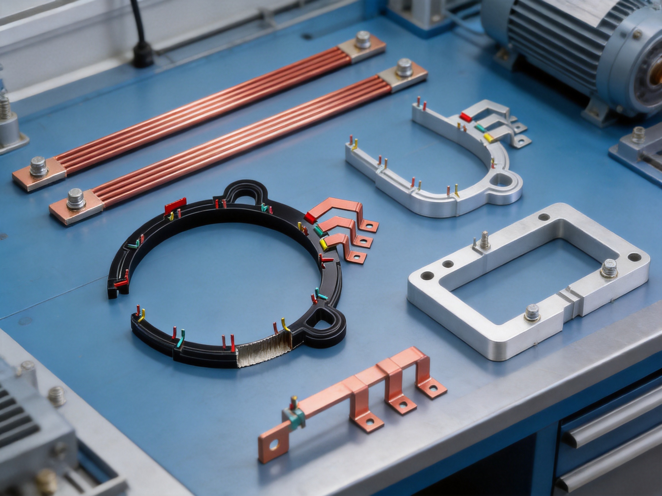
A major advantage of the insulated enameled motor busbar is the integration of electrical conduction, insulation, and mechanical positioning in one engineered component. Conventional bare busbars may require additional sleeves, barriers, spacers, brackets, or insulating films. These separate components can increase the number of assembly operations and create additional opportunities for misalignment.
By combining the conductive profile with enamel insulation and, where required, injection-molded fixing features, the product can be designed around the motor’s actual architecture. This supports more efficient use of internal space and can simplify the customer’s assembly process.
Compact Insulation Structure
Enamel insulation can provide a compact alternative to bulky external insulation systems. This is valuable for motors with narrow internal clearances or densely arranged windings. A smaller insulation footprint can help engineers optimize the conductor route and potentially reduce the size of the connection area.
Compact construction is especially relevant to electric vehicle traction motors and other systems in which power density is a key design objective. More efficient use of space can support smaller motor housings, improved packaging, or additional room for cooling and control components.
Stable High-Current Transmission
The use of high-purity T2 or C11000 copper and 1060 or 1070 aluminum provides a dependable conductive base. Correctly dimensioned busbars offer low resistance, stable current transmission, and reduced heat generation compared with undersized or poorly fitted conductors.
Unlike flexible cables that may require multiple strands, crimped terminals, and additional routing space, a shaped busbar provides a defined conductive path. This can help minimize unnecessary bends and connection points. Fewer connection interfaces may reduce potential sources of resistance and mechanical loosening.
Improved Assembly Consistency
Custom shapes and integrated fixing structures can improve repeatability during motor assembly. The busbar is produced to a defined geometry rather than being manually formed or routed by individual operators. This supports consistent alignment with terminals, housings, winding connections, and control components.
Repeatable assembly is important in high-volume manufacturing. A component that consistently fits the intended location can reduce rework, minimize installation errors, and support more predictable production cycle times.
High Temperature Capability
Motor environments can expose connection components to continuous heat, temperature cycling, electrical overloads, vibration, and cooling variations. Enameled insulation classes of 130°C, 155°C, and 180°C provide options for different thermal conditions.
The insulation class should always be selected according to the complete thermal design of the motor. However, the availability of multiple classes gives engineers greater flexibility when specifying components for standard motors, high-speed motors, high-power-density systems, and demanding new energy applications.
Resistance to Mechanical Stress
Motor busbars must remain stable while exposed to vibration, electromagnetic forces, thermal expansion, and assembly loads. A properly formed copper or aluminum conductor offers good mechanical strength, while integrated plastic supports can help control movement and protect the insulation system.
The product can be engineered with appropriate bend geometry, support spacing, and fixing locations. This helps reduce stress concentration and can improve resistance to deformation. The result is a connection component suited to applications in which mechanical reliability is as important as electrical performance.
Material and Weight Flexibility
The availability of copper and aluminum allows the busbar to be optimized for different priorities. Copper is well suited to high current density and compact designs. Aluminum can help reduce weight and material cost when the design can accommodate its electrical characteristics.
This flexibility gives motor designers more options than a single-material product range. The manufacturer can evaluate the customer’s operating conditions and recommend a suitable conductor material, cross-section, surface treatment, and insulation class.
Technical Parameters
| Parameter | Available Specification | Engineering Consideration |
|---|---|---|
| Conductor material | T2 or C11000 copper; 1060 or 1070 aluminum | Selected according to conductivity, weight, current, and cost requirements |
| Insulation type | Enameled insulation layer | Provides electrical separation and compact protection |
| Temperature class | Class B, 130°C; Class F, 155°C; Class H, 180°C | Matched to operating temperature and thermal cycling |
| Thickness | Approximately 1 mm to 15 mm | Determined by current, mechanical strength, and available space |
| Width | Approximately 5 mm to 200 mm | Customized to the conductor profile and installation area |
| Length | Custom according to drawing | Adapted to motor architecture and connection distance |
| Shape | Customized straight, bent, stepped, or complex profiles | Designed for direct integration into the customer’s assembly |
| Processing | Laser cutting, stamping, bending, punching, and tapping | Selected according to geometry, volume, and tolerance |
| Surface treatment | Bare, tin plating, nickel plating, or silver plating | Chosen for corrosion protection and connection compatibility |
| Standards | RoHS, ISO, IEC, and CE requirements may be supported | Final compliance depends on the project specification |
The parameters above are general customization ranges rather than a single fixed product configuration. Each motor busbar should be engineered according to actual current, voltage, frequency, temperature, insulation clearance, vibration, installation space, and joining requirements.
Applications in Electric Vehicles and New Energy Motors
Electric vehicle motors require compact, lightweight, and highly reliable electrical connection components. The motor may operate at high current while experiencing rapid acceleration, regenerative braking, temperature fluctuations, vibration, and limited internal space. An insulated enameled busbar can help address these requirements through a combination of compact insulation, customized geometry, and stable conductivity.
In traction motor systems, the busbar may connect windings, terminals, inverter interfaces, or internal motor sections. The exact design depends on the motor architecture and the position of the power electronics. Copper may be selected for high current density, while aluminum may be considered when weight reduction is a primary concern.
New energy motor control systems also benefit from carefully designed connection components. A busbar can be formed to match the arrangement of switching devices, control modules, sensors, and motor terminals. Custom openings and fixing points can support direct installation and reduce the need for multiple separate conductors.
Because electric vehicle components are produced in large volumes, manufacturing consistency is essential. Digital production lines, controlled tooling, and repeatable inspection procedures help support stable quality from batch to batch.
Applications in Industrial and Servo Motors
Industrial motors are used in pumps, compressors, conveyors, machine tools, fans, robotics, and production equipment. These systems may operate continuously and may be exposed to dust, vibration, temperature changes, or frequent start-stop cycles. The motor connection system must therefore provide consistent electrical performance over an extended service period.
Servo motors require accurate and stable electrical connections because they support precise motion control. A custom-shaped busbar can be designed to fit within a compact housing while maintaining controlled routing and reliable connection points. Integrated fixing features may help protect the conductor from movement during rapid acceleration and deceleration.
High-speed motors create additional demands because rotational speed may increase vibration and thermal stress. The busbar’s mechanical shape, support points, insulation class, and connection method should be selected as part of the complete motor design. The ability to customize these features is a significant advantage over generic conductors.
Applications in Generators and Power Equipment
Generators and power equipment often require conductors capable of handling substantial currents while maintaining dependable insulation. Custom busbars can be used in connection assemblies where space, access, and mechanical support must be considered together.
In power equipment, the busbar may be installed close to other conductors or metallic structures. The enamel insulation helps reduce the risk of unintended electrical contact. Additional molded support structures can help maintain spacing and prevent movement caused by vibration or thermal expansion.
Surface treatment may be selected according to the surrounding environment and connection method. For example, plated connection areas may be useful where long-term contact stability or corrosion protection is required. Engineering decisions should be based on the operating voltage, current, humidity, temperature, and maintenance conditions of the equipment.
Applications in Tools, Appliances, and Automation
Power tools and household appliances often require compact electrical assemblies that can be produced efficiently and installed quickly. Custom busbars can replace certain cable and terminal combinations, especially where a rigid, repeatable connection path is preferred.
Industrial automation equipment may use motors and actuators in compact modules. The busbar can be designed around the actuator housing, motor winding, controller, or terminal block. Precision holes, bends, and fixing components support faster assembly and may help reduce the risk of wiring errors.
For high-volume appliance production, the ability to produce a repeatable custom part is important. Once the tooling and manufacturing process have been validated, the same geometry can be reproduced with consistent dimensions and insulation coverage across multiple production batches.
Quality Control and Reliability Considerations
Material Verification
Reliable performance begins with the correct conductor material. Copper and aluminum grades should be verified according to the approved specification. Material identification, dimensional measurement, and surface inspection help ensure that the conductor meets the design requirements before further processing.
Dimensional Inspection
Dimensional accuracy affects both electrical performance and assembly fit. Important inspection points may include thickness, width, overall length, bend angles, hole diameter, hole position, terminal geometry, and molded support location.
For complex busbars, three-dimensional measurement or dedicated inspection fixtures may be used to confirm the profile. Maintaining consistent geometry helps ensure that the busbar aligns correctly with the customer’s motor housing and connection points.
Insulation Inspection
The enamel layer should be checked for uniform coverage, visible damage, exposed conductive areas, contamination, and other defects. Electrical insulation testing may be performed according to the product specification and applicable industry requirements.
Inspection criteria should distinguish between intentional bare connection areas and areas that must remain insulated. This is particularly important when the product includes several terminals or when insulation is selectively removed for assembly.
Mechanical and Functional Evaluation
Depending on the application, testing may include bending evaluation, dimensional stability, adhesion assessment, temperature exposure, vibration testing, and electrical resistance measurement. The exact test plan should be agreed upon during product development.
Functional evaluation may also include trial installation into the motor assembly. This confirms that the busbar can be fitted without excessive force and that the molded fixing features, holes, terminals, and bends perform as intended.
Why Choose a Specialized Manufacturer?
A specialized manufacturer can provide more than a standard copper or aluminum strip. The value lies in the ability to coordinate material selection, conductive geometry, insulation, metal forming, injection molding, surface treatment, inspection, and application engineering.
Zhejiang Zhongyan New Energy Co., Ltd. focuses on new energy conductive components and precision electrical connection products. Its experience includes high-voltage copper foil soft connections, special-shaped flexible connections, battery soft connections, and other components used in electric vehicles, energy storage, rail transit, communications, and power transmission systems.
The company combines engineering personnel, digital production equipment, product development capabilities, and quality management procedures. This combination supports both standard manufacturing and customized projects based on customer drawings or application requirements.
Its development experience in battery connection systems and new energy components is relevant to motor busbar production because both product categories require low resistance, controlled insulation, reliable mechanical performance, and high consistency. Experience with polymer diffusion welding and laser technology also demonstrates a focus on advanced processing for precision conductive components.
Established in 2022, the company has developed relationships with major enterprises in the new energy sector and continues to expand its capabilities in battery cells, connection systems, energy storage, and integrated electrical solutions. Its technical direction is centered on safe, reliable, and highly integrated conductive components.
Customization Process for OEM Projects
Step One: Requirement Review
The project begins with a review of the customer’s drawings, samples, electrical requirements, installation conditions, and expected production volume. Information about current, voltage, temperature, insulation class, material, surface treatment, and assembly method is collected at this stage.
Step Two: Design and Feasibility Analysis
Engineers analyze the proposed geometry and identify potential manufacturing issues. Bend radii, hole positions, contact areas, insulation zones, and injection-molded support features are reviewed. If necessary, the design is adjusted to improve manufacturability, assembly, or reliability.
Step Three: Tooling and Prototype Development
For products with complex shapes or molded fixing parts, dedicated molds and forming tools may be developed. Prototype samples allow the customer to confirm fit, electrical connections, insulation clearances, and assembly procedures before mass production.
Step Four: Process Validation
Once the prototype is approved, the manufacturing sequence is validated. This may include material preparation, cutting, stamping, forming, punching, tapping, insulation application, injection molding, plating, and final inspection. Process parameters are documented to support repeatable production.
Step Five: Batch Production and Inspection
After validation, the busbars are produced in accordance with the approved specifications. Inspection is performed at appropriate stages to identify dimensional, surface, insulation, and assembly-related issues. Production records and quality controls help support batch consistency.
Step Six: Continuous Improvement
Customer feedback, field information, and production data can be used to improve tooling, materials, insulation, and assembly procedures. Continuous improvement is particularly valuable for electric vehicle and industrial motor programs that develop through multiple product generations.
Design Guidance for Engineers
When specifying an insulated motor busbar, engineers should begin with the required continuous and peak current. The conductor cross-section must be sufficient for the electrical load and thermal environment. Short-term overload conditions should also be considered, especially in traction motors and servo applications.
The operating temperature should be evaluated at the hottest location rather than only at the ambient environment. Motor windings, inverters, bearings, cooling channels, and adjacent conductors can all influence the busbar’s thermal exposure. The insulation temperature class should provide an appropriate margin for normal operation and foreseeable temperature peaks.
Mechanical loads should be considered together with electrical requirements. Vibration, electromagnetic force, thermal expansion, assembly pressure, and repeated service cycles may affect the conductor. Fixing points and molded supports should be placed to control movement without creating excessive stress concentration.
Connection areas should be clearly defined. If the product will be bolted, welded, soldered, or connected through a terminal, the surface finish and exposed metal area must be selected accordingly. Plating may be necessary to improve corrosion resistance or contact stability.
Designers should also consider inspection access and installation sequence. A busbar that is electrically excellent but difficult to install may increase production cost. Integrated fixing structures, clear orientation features, and repeatable geometry can make a significant difference in assembly efficiency.
Environmental and Compliance Considerations
Modern electrical equipment increasingly requires materials and manufacturing processes that support environmental responsibility. Copper and aluminum are widely used conductive materials with established recycling pathways. Efficient material utilization and optimized component design can also help reduce unnecessary mass and waste.
RoHS requirements may be considered for products supplied to markets that restrict hazardous substances. Depending on the project, ISO, IEC, and CE-related requirements may also be relevant. The final compliance requirements should be established between the customer and manufacturer because they depend on the end product, market, voltage level, and application category.
Insulation materials, plating systems, plastic fixing components, and manufacturing chemicals should be selected with attention to environmental, safety, and regulatory requirements. Documentation and test records can support the customer’s compliance and product approval processes.
Comparison with Alternative Connection Methods
| Connection Method | Typical Strength | Potential Limitation | Where an Insulated Motor Busbar May Offer an Advantage |
|---|---|---|---|
| Bare rigid busbar | Simple and highly conductive | May require separate insulation and support components | Integrated enamel insulation and customized fixing features can simplify assembly |
| Flexible cable | Good routing flexibility | May require terminals, crimping, supports, and additional space | Defined geometry and fewer connection interfaces can improve repeatability |
| Insulated wire harness | Easy adaptation to many circuits | Can occupy more space and require extensive routing | Compact shaped conductors may support higher power density |
| Stamped terminal assembly | Efficient for standardized high-volume designs | Less suitable for complex three-dimensional routing | Custom bending and molding can accommodate unusual motor geometries |
| Separate metal bracket and conductor | Components can be independently replaced | More parts and assembly operations | Integrated conductor and support structure can reduce part count |
No single connection method is ideal for every motor. The most appropriate solution depends on current, space, flexibility, cost, production volume, environmental conditions, and assembly requirements. The value of the insulated enameled busbar is its ability to combine several functions in a compact, engineered part.
Benefits for Production and Supply Chain Management
Customized busbars can support more efficient production by reducing manual shaping and simplifying connection procedures. When the part arrives with the correct bends, holes, insulation, and support features, the customer can install it according to a defined process rather than adapting a generic conductor on the assembly line.
Reduced assembly variation can contribute to lower rework rates and more consistent electrical performance. It can also make operator training easier because the component has a clear orientation and defined installation position.
From a supply chain perspective, a specialized supplier can consolidate multiple processes into one controlled production program. Instead of sourcing a metal strip, separate insulation, brackets, and additional machining from different vendors, the customer may obtain a more complete finished component from one manufacturing partner.
Single-source coordination can simplify communication, quality documentation, engineering changes, and production scheduling. It may also make it easier to implement design improvements when the conductor, insulation, and molded support are developed together.
Future Development of Motor Busbars
Motor systems are moving toward higher power density, smaller dimensions, greater electrification, and more integrated control architectures. These trends increase the need for connection components that can handle higher current while occupying less space.
Future busbar development is likely to focus on improved thermal management, lower resistance, lightweight materials, more sophisticated insulation systems, and integrated sensing or control features. Customized injection molding may also support more complex electrical assemblies with fewer separate components.
Electric vehicles and energy storage systems will continue to require reliable conductive parts that can operate under demanding thermal and mechanical conditions. Experience in battery connection systems, flexible copper connections, and precision metal processing can support the development of next-generation motor busbars.
Digital manufacturing will remain important as product geometries become more complex and customers require faster development cycles. Digital models, automated equipment, process data, and inspection systems can help manufacturers respond efficiently to customized designs while maintaining stable quality.
Questions and Answers
What is the main function of an insulated enameled motor busbar?
Its main function is to transmit electrical current through a motor or power assembly while providing an insulating surface that helps prevent unintended electrical contact. The busbar can also provide a defined mechanical connection path when shaped and supported for a specific application.
Which materials are available?
The primary conductor materials are T2 or C11000 copper and 1060 or 1070 aluminum. Copper is often selected for high conductivity and compact dimensions, while aluminum can be selected when lower weight and cost efficiency are important.
What insulation temperature classes are available?
Common options include Class B at 130°C, Class F at 155°C, and Class H at 180°C. The correct class should be selected according to the motor’s thermal design and operating conditions.
Can the busbar be manufactured according to a drawing?
Yes. The product can be customized according to customer drawings, three-dimensional models, samples, or technical specifications. Shape, thickness, width, length, holes, bends, connection areas, insulation zones, and fixing structures can be developed for the intended assembly.
Can fixing parts be integrated into the busbar?
Yes. Plastic injection molding can be used to create fixing structures around selected sections of the enameled conductor. These structures can help position the busbar, maintain spacing, and reduce the number of separate assembly parts.
What processing methods are available?
Available processes include laser cutting, stamping, bending, punching, tapping, insulation application, injection molding, and optional surface treatments such as tin, nickel, or silver plating.
Is aluminum suitable for motor busbars?
Aluminum can be suitable when the design prioritizes low weight and cost efficiency. Because aluminum has different electrical and mechanical characteristics from copper, the conductor dimensions, connection method, and thermal design should be evaluated for each project.
Can copper busbars be used in electric vehicle motors?
Yes. Copper is widely suitable for electric vehicle motor applications because of its high conductivity, compact current-carrying capability, and compatibility with various forming and connection processes.
How does the product compare with flexible cable?
A shaped busbar provides a defined conductive path and may reduce the need for multiple terminals, supports, and routing operations. Flexible cable may remain preferable where extensive movement or highly variable routing is required. The choice depends on the motor design and installation conditions.
What information should be provided for a quotation?
Useful information includes conductor material, current, voltage, dimensions, shape, drawing or sample, insulation class, temperature range, surface treatment, connection method, quantity, inspection requirements, and intended application.
Can the busbar support high-current applications?
Yes. High-purity copper or appropriately dimensioned aluminum can provide stable current transmission for high-current applications. The cross-section and thermal design must be calculated according to continuous current, peak current, ambient temperature, cooling, and duty cycle.
What industries can use these products?
Applications include electric vehicles, industrial motors, servo motors, generators, motor control systems, power tools, household appliances, industrial automation, renewable energy equipment, rail transit, communications equipment, and energy storage systems.
Conclusion
Insulated enameled copper and aluminum motor busbars provide a practical solution for electrical systems that require high conductivity, compact insulation, reliable mechanical positioning, and customized geometry. By combining precision metal processing with enamel insulation and optional plastic injection molding, these components can address many of the limitations associated with bare busbars, flexible cables, and multi-part connection assemblies.
The products support copper and aluminum material choices, temperature classes from 130°C to 180°C, customized thicknesses and widths, complex three-dimensional shapes, optional plating, and a range of precision manufacturing processes. These capabilities make them suitable for electric vehicle motors, industrial equipment, generators, servo systems, power tools, household appliances, and other high-current applications.
Zhejiang Zhongyan New Energy Co., Ltd. contributes expertise in new energy conductive components, battery connection systems, flexible copper connections, precision processing, digital production, and customized electrical solutions. Its integrated manufacturing approach helps customers develop busbars that are not only electrically conductive, but also mechanically stable, space-efficient, and compatible with modern automated assembly.
For customers seeking a reliable motor connection component, the most important advantage is the ability to develop the conductor as part of the complete electrical and mechanical system. Through material selection, insulation design, precision forming, injection molding, and controlled inspection, an insulated enameled motor busbar can support safer, more efficient, and more consistent motor production.
References
1. International Electrotechnical Commission. Electrical Insulation Systems and Thermal Classification Principles.
2. International Electrotechnical Commission. Low-Voltage Switchgear and Controlgear Busbar and Connection Requirements.
3. International Organization for Standardization. Quality Management Systems and Manufacturing Process Control Principles.
4. European Union. Restriction of Hazardous Substances Requirements for Electrical and Electronic Equipment.
5. Copper Development Association. Technical Principles of Copper Electrical Conductivity and Busbar Design.
6. Aluminum Association. Engineering Characteristics and Electrical Applications of Aluminum Conductors.
7. Automotive and New Energy Industry Guidance. Electrical Connection Design for Traction Motors and High-Voltage Systems.
8. General Motor Engineering Practice. Thermal Management, Vibration Resistance, and Insulation Coordination in Electric Motors.
Product: Insulated Enameled Copper & Aluminum Motor Busbar | Precision Metal Parts

Driven by the development of new energy and aiming for "zero carbon".
Copyright © Zhejiang Zhongyan New Energy Co., Ltd. All Rights Reserved.
