 English
 Español

Insulated Flexible Busbars for Automotive Batteries, New Energy Systems, and Power Grids
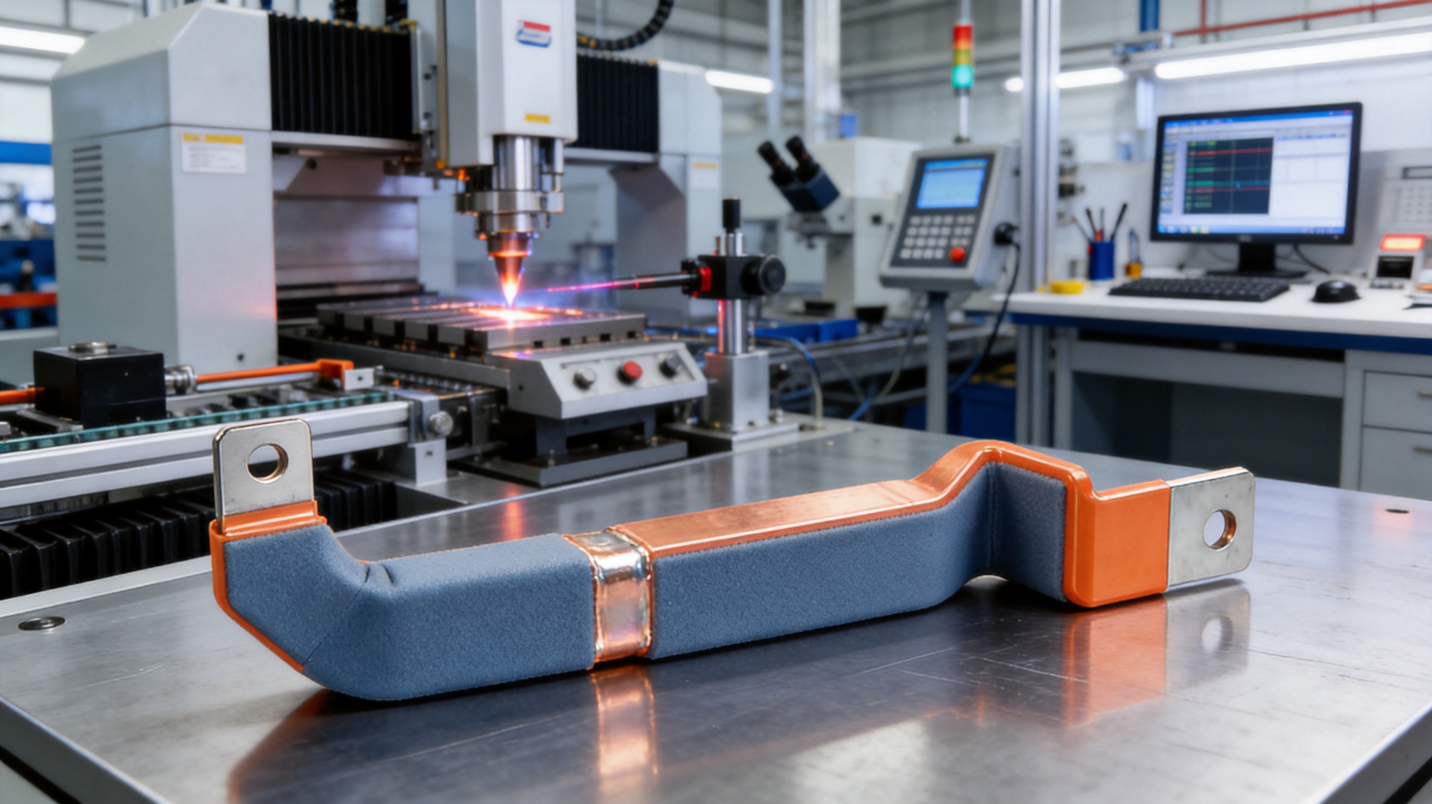
Insulated flexible busbars are becoming essential components in modern electrical systems that demand high current capacity, compact packaging, dependable insulation, and long-term mechanical reliability. Automotive battery packs, energy-storage cabinets, charging equipment, industrial power supplies, and new power-grid systems all require conductive connections that can manage high electrical loads while accommodating movement, vibration, thermal expansion, and restricted installation space.
The insulated flexible busbar described in this article is designed for these demanding applications. It combines a high-conductivity T2 copper conductor with an engineered insulation layer and digitally controlled processing technology. The result is a configurable electrical connection solution for battery modules, high-voltage distribution systems, and industrial equipment. Depending on the required structure, the product can incorporate flexible copper sections, rigid terminal areas, welded connections, crimped terminals, or a hybrid arrangement that combines rigid and flexible zones.
Compared with conventional rigid copper bars, cable assemblies, and less precisely manufactured flexible connectors, this product offers a balanced combination of current-carrying performance, installation flexibility, heat dissipation, insulation protection, dimensional consistency, and customization capability. It is especially suitable for original equipment manufacturers and system integrators that need repeatable components rather than generic off-the-shelf conductors.
Content
- 1. The Role of Flexible Busbars in Modern Power Systems
- 2. Product Overview
- 3. High-Conductivity T2 Copper Construction
- 4. Flexible and Rigid Sections in One Connection
- 5. Insulation Performance and Halogen-Free Options
- 6. Digital Processing and Manufacturing Consistency
- 7. Advanced Joining and Connection Technology
- 8. Thermal Performance and Heat Dissipation
- 9. Oxidation Resistance and Environmental Durability
- 10. Advantages Compared with Conventional Alternatives
- 11. Application in Automotive Battery Systems
- 12. Application in Energy Storage and LiFePO4 Systems
- 13. Application in New Power-Grid Equipment
- 14. Additional Industrial Applications
- 15. Engineering and Customization Process
- 16. Quality Management and Technical Strengths
- 17. Product Selection Guidelines
- 18. Installation and Handling Recommendations
- 19. Frequently Asked Questions
- What is an insulated flexible busbar?
- Why is T2 copper used?
- Can the busbar be used in LiFePO4 battery systems?
- What is the advantage of combining rigid and flexible sections?
- What current ratings are available?
- What section areas are available?
- Can the product use halogen-free insulation?
- Are welded and crimped terminals available?
- Can the busbar be made for a customer’s drawing?
- How does digital processing improve the product?
- What industries can use this product?
- How should the correct busbar be selected?
- 20. Conclusion
- References
- Product: Automotive Batteries New Energy Power Grids Flexible Connector
1. The Role of Flexible Busbars in Modern Power Systems
A busbar is a conductive component used to distribute electrical current between batteries, terminals, modules, switches, inverters, circuit protection devices, and other equipment. Traditional busbars are often manufactured as rigid copper or aluminum strips. They provide a low-resistance current path, but they may be difficult to install when equipment has irregular geometry, limited clearance, or components that move relative to one another.
An insulated flexible busbar addresses these limitations by using a conductive structure that can tolerate controlled bending and mechanical displacement. The flexible portion can be positioned around battery cells, power electronics, or enclosure features while maintaining an efficient current path. Insulation surrounding the conductor helps prevent accidental contact, short circuits, contamination, and damage caused by installation or operation.
In battery systems, the connection between cells and modules must remain electrically stable despite repeated changes in temperature, vibration, assembly tolerances, and current demand. A rigid component may transfer mechanical stress to terminals or cell housings. A flexible connector can absorb part of that stress and reduce the need for complex routing. When the flexible section is combined with precisely formed rigid terminal zones, the resulting hybrid busbar can simplify both electrical design and mechanical assembly.
In power-grid and industrial applications, flexible busbars are useful where equipment must be connected across a short but complicated route. They can be installed inside switchgear, energy-storage systems, battery cabinets, converter assemblies, and high-current distribution units. Their compact form can also help reduce the space required for cable bends and terminal supports.
2. Product Overview
The product is an insulated flexible busbar intended for automotive batteries, new energy equipment, power grids, and high-current electrical systems. It is manufactured using T2 copper conductive connecting bars or copper-based conductive components. T2 copper is widely used in electrical applications because it offers good conductivity, ductility, forming performance, and compatibility with welding and terminal processing.
The insulation layer uses an insulating material suitable for the new energy industry. A halogen-free option is available for applications where reduced corrosive smoke, environmental compliance, and improved material safety are important. The insulating layer is designed to provide surface insulation and protect the conductive body from unintended contact with adjacent components.
Product designs can be customized according to the required section area, current rating, terminal geometry, length, bend position, hole pattern, insulation color, insulation coverage, and connection method. Available specifications include conductor section areas from approximately 10 mm² to 1200 mm², current ratings from approximately 50 A to 2500 A, operating temperatures from -40°C to 125°C, and withstand-voltage ranges from 600 V to 1000 V. Final performance depends on the product configuration, installation conditions, environmental requirements, and validation results.
The connection may be produced with welded or crimped terminals. These options allow the busbar to be integrated into different battery and power-distribution architectures. Some applications require a welded connection for a compact, low-resistance interface. Others require crimped terminals for a serviceable or mechanically standardized assembly.
| Product Parameter | Typical Range or Option | Application Significance |
|---|---|---|
| Conductor material | T2 copper or tinned copper | Supports high-current conductivity and terminal processing |
| Insulation material | Halogen-free insulating material available | Improves electrical separation and supports environmental requirements |
| Operating temperature | -40°C to 125°C | Suitable for automotive, storage, industrial, and outdoor equipment environments |
| Withstand voltage | 600 V to 1000 V | Supports low-voltage and high-voltage electrical architectures |
| Section area | 10 mm² to 1200 mm² | Allows configuration for different current levels and installation spaces |
| Current rating | 50 A to 2500 A | Suitable for battery modules, distribution assemblies, and high-power equipment |
| Connection type | Welded or crimped terminals | Provides flexibility for different assembly and service strategies |
| Compliance direction | RoHS, UL, and IEC requirements can be considered | Supports international product development and qualification programs |
3. High-Conductivity T2 Copper Construction
The conductor is one of the most important elements in any high-current connection. T2 copper is selected because it combines useful electrical conductivity with good forming and joining characteristics. In a flexible busbar, the conductor must not only carry current efficiently; it must also tolerate forming, bending, terminal preparation, welding, and the mechanical conditions of the finished assembly.
High conductivity helps reduce voltage drop and resistive power loss. Lower electrical resistance can also reduce the amount of heat generated during operation, although actual thermal performance depends on current, ambient temperature, installation method, surface area, airflow, insulation design, and the surrounding components. A properly engineered copper busbar can provide a more direct and compact current path than a collection of smaller wires.
The use of a broad copper conductive section can also help distribute current over a larger area. This may be valuable in battery packs and power-distribution assemblies where current concentration at a narrow contact point could create unwanted heating. Terminal geometry, weld quality, contact pressure, and surface treatment remain important factors in achieving the expected electrical performance.
Tinned copper can be selected when the application requires additional protection against oxidation or improved compatibility with a particular terminal or joining process. Tinning may also support more stable contact behavior in environments where humidity, contamination, or corrosive exposure is a concern. The appropriate conductive surface should be selected according to the electrical, thermal, mechanical, and environmental requirements of the application.
4. Flexible and Rigid Sections in One Connection
A major advantage of this product category is the ability to combine flexible sections with rigid terminal areas. A fully rigid busbar may be strong and easy to model, but it can be difficult to install in a compact battery enclosure. A fully flexible conductor may route easily, but it may not provide the exact terminal geometry or support required at mounting points. A hybrid structure seeks to provide the advantages of both approaches.
The flexible section can accommodate minor positional variation, assembly tolerance, vibration, and thermal expansion. The rigid section can provide a stable interface for a terminal, fastener, welded joint, crimped connector, or busbar support. This design can reduce the need for additional adapters and may simplify the routing of high-current connections.
For battery modules, hybrid busbars can be designed around cell spacing, module frames, sensing points, and enclosure walls. For power electronics, the rigid areas can align with inverter or converter terminals while the flexible section routes around heat sinks, barriers, or structural elements. For new power-grid equipment, the same principle can be applied to compact distribution units and switching assemblies.
Compared with a conventional rigid copper bar, a flexible or hybrid busbar may reduce installation stress. It can also reduce the need for manual adjustment during assembly. When dimensions are developed from accurate three-dimensional drawings and validated through sample fitting, the production part can improve assembly repeatability for OEM customers.
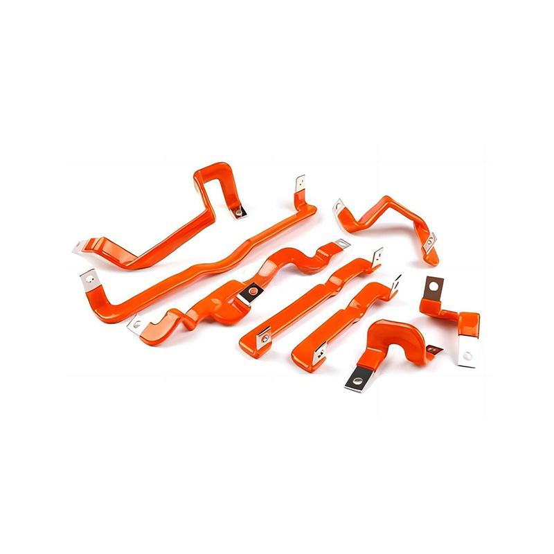
Automotive Batteries New Energy Power Grids Flexible Connector
5. Insulation Performance and Halogen-Free Options
Insulation is not merely an external covering. It is an important part of the electrical safety system. The insulation layer must maintain separation between the conductive component and neighboring parts while tolerating the temperature, vibration, bending, and environmental exposure associated with the equipment.
The product uses insulation treatment technology developed for new energy applications. This approach is intended to provide stable surface insulation and consistent coverage over the conductive structure. The insulation design can be adapted to the required coverage area, terminal exposure, bend geometry, and assembly method. In some designs, the terminal zone is left exposed for welding or crimping while the remainder of the conductor is insulated.
Halogen-free insulation is available for projects that prioritize reduced toxic and corrosive emissions during fire conditions. Halogen-free materials can help support RoHS-related environmental objectives and may be evaluated according to IEC 60754 requirements concerning halogen acid gas emissions. The specific material grade and certification path should be confirmed for each project because compliance depends on the complete material system, manufacturing process, and test results.
In high-voltage battery and energy-storage systems, insulation design must also consider creepage distance, clearance, surface contamination, condensation, and the possibility of mechanical damage. A product specification should therefore define not only nominal voltage but also the environmental category and installation arrangement. The manufacturing team can support customers in determining suitable insulation coverage and terminal spacing during the design stage.
The insulated surface may also contribute to protection against oxidation, dust, accidental contact, and handling damage. However, insulation does not replace correct system-level protection. Designers must still provide suitable fuses, disconnect devices, barriers, grounding arrangements, monitoring systems, and mechanical supports where required.
6. Digital Processing and Manufacturing Consistency
High-current connectors often look simple, but their performance depends on numerous dimensional and process details. Conductor thickness, terminal width, hole location, bend angle, insulation coverage, weld position, and surface condition can all affect installation and electrical performance. Manual processing without controlled parameters can lead to variation between batches.
The manufacturer uses digital processing equipment to standardize key manufacturing parameters. Digital processing can help translate customer drawings and three-dimensional data into repeatable cutting, forming, drilling, punching, welding, and insulation operations. It also supports the creation of production records and process instructions for future orders.
Standardized parameters are particularly important for custom busbars. OEM customers may require several related parts with different lengths, terminal orientations, and bend positions. Digital manufacturing helps reduce the risk of confusing similar parts and supports more reliable repeat production after the initial sample has been approved.
Process control may include incoming material verification, dimensional inspection, conductor preparation, forming control, terminal processing, insulation inspection, electrical testing, and final packaging review. The exact inspection plan can be adapted according to product complexity and customer requirements.
Digital production also supports engineering changes. When a battery enclosure is revised, the busbar geometry may need to change. A controlled digital workflow makes it easier to update the design, review the revised drawing, produce a sample, and preserve the approved version for later production. This can shorten the communication cycle between the customer, engineering team, and production department.
7. Advanced Joining and Connection Technology
Terminal joining is a critical part of busbar performance. A conductor may have excellent intrinsic conductivity, but an improperly formed or joined terminal can increase contact resistance, create localized heating, and reduce service life. For this reason, the connection method must be selected at the beginning of the design process.
Welded terminals can provide a compact connection with a low-profile interface. Welding may be suitable for battery modules, high-current assemblies, and applications where the connection should remain permanent. The welding method, energy input, electrode condition, surface cleanliness, and joint geometry must be controlled to achieve consistent results.
Crimped terminals can offer a standardized mechanical and electrical connection. They may be useful where serviceability, replacement, or compatibility with existing harness and terminal systems is important. Crimp height, compression ratio, pull-out strength, conductor insertion, and terminal material must be controlled and verified.
The company’s experience with copper foil soft connections, battery soft connections, and special-shaped flexible connections provides a foundation for developing customized terminals. The production team can evaluate the customer’s current, voltage, space, vibration, and assembly requirements before recommending a welded, crimped, or combined structure.
For demanding applications, joining quality should be evaluated through electrical resistance testing, mechanical strength testing, visual inspection, cross-sectional analysis, thermal cycling, vibration testing, and other qualification methods. The final test plan depends on the intended use and customer standards.
8. Thermal Performance and Heat Dissipation
Heat management is a fundamental consideration in high-current electrical equipment. When current flows through a conductor, electrical resistance produces heat. If heat cannot be removed effectively, the temperature of the conductor and surrounding components may rise. Excessive temperature can accelerate insulation aging, increase contact resistance, and reduce system reliability.
A copper flexible busbar can support heat dissipation through its conductive cross-section and exposed or insulated surface area. Compared with a tightly bundled group of small wires, a broad busbar may provide a more direct heat-transfer path, depending on the application layout. The final thermal result depends on the current waveform, duty cycle, ambient temperature, enclosure design, airflow, insulation thickness, and contact quality.
The product can be engineered for different current ratings and section areas. Larger cross-sections are generally used for higher current requirements, but the correct selection must be based on the actual operating profile rather than current alone. Continuous current, short-time overload, peak current, ambient temperature, cooling conditions, and acceptable temperature rise should all be evaluated.
Flexible sections must also be designed so that bending does not create sharp folds, excessive compression, or local damage to the insulation. Correct bend radii and support positions help preserve both thermal and mechanical performance. A busbar that is forced into an unsuitable route may experience additional resistance or stress even if its nominal specification is adequate.
For battery and energy-storage applications, thermal analysis may be performed together with the enclosure and cell design. This system-level approach helps identify hot spots near terminals, welds, fuse connections, and tightly packed conductors. The manufacturer can use the customer’s operating data to assist in selecting a suitable conductor configuration.
9. Oxidation Resistance and Environmental Durability
Copper can be affected by oxidation and environmental exposure. Oxidized surfaces may influence contact resistance, solderability, weldability, and appearance. Protective insulation and suitable surface treatments can help reduce exposure of the conductor to moisture, oxygen, dust, and chemical contaminants.
The product is designed with oxidation resistance in mind. Tinned copper may be selected when additional surface protection is beneficial. Insulation can protect much of the conductive body after assembly, while exposed terminal areas can be processed or treated according to the joining method.
Automotive and transportation applications may experience vibration, humidity, salt exposure, temperature cycling, and rapid changes in operating conditions. Energy-storage equipment may be installed indoors, outdoors, or in semi-protected industrial environments. Mining and explosion-proof equipment may introduce additional requirements related to dust, impact, and safety classification.
Environmental durability should be verified using tests appropriate to the application. These may include temperature cycling, damp heat, salt spray, vibration, mechanical shock, insulation resistance, dielectric withstand, and aging tests. The manufacturer can work with customers to establish a qualification program based on the equipment’s intended environment.
10. Advantages Compared with Conventional Alternatives
10.1 Compared with Rigid Copper Busbars
Rigid copper busbars are effective where the connection path is straight, stable, and easy to support. However, they may require tight dimensional control across the entire assembly and may transfer mechanical stress to connected terminals. Installation can become difficult when the battery or cabinet has complex internal geometry.
The insulated flexible busbar provides greater routing flexibility. Its flexible section can compensate for small variations in position and reduce the need for forced alignment. The rigid terminal zones can still provide a stable mounting and joining interface. This combination is useful when the customer needs both mechanical stability and installation adaptability.
10.2 Compared with Individual Cables
Cables are highly flexible and widely available, but high-current cable assemblies can require large bend radii, multiple lugs, extra supports, and additional insulation protection. They may also occupy more space in compact battery modules or switchgear.
A flexible busbar can provide a flatter, more integrated route. Its shape can be designed around the equipment, potentially reducing the number of separate supports and improving assembly organization. The broad conductive section can also offer a direct current path. The best choice depends on the installation space, required movement, current profile, service strategy, and certification requirements.
10.3 Compared with Generic Flexible Connectors
Generic flexible connectors may offer limited choices of length, terminal position, conductor size, insulation material, or connection type. They may not be optimized for a specific battery or power-distribution assembly.
A custom product can be developed from the customer’s mechanical and electrical data. This allows the conductor, terminal, insulation, bend area, and joining method to be coordinated as one assembly. Customization can reduce trial-and-error during installation and support more consistent production for OEM programs.
10.4 Compared with Less Controlled Manufacturing
Inconsistent forming, cutting, welding, or insulation application can create differences between individual parts. These differences may complicate assembly and make it difficult to identify the source of field problems.
Digital processing and documented manufacturing parameters improve repeatability. Engineering drawings, inspection standards, process records, and sample approval can establish a clear reference for future production. This is especially valuable for customers operating multiple production lines or supplying equipment across different markets.
11. Application in Automotive Battery Systems
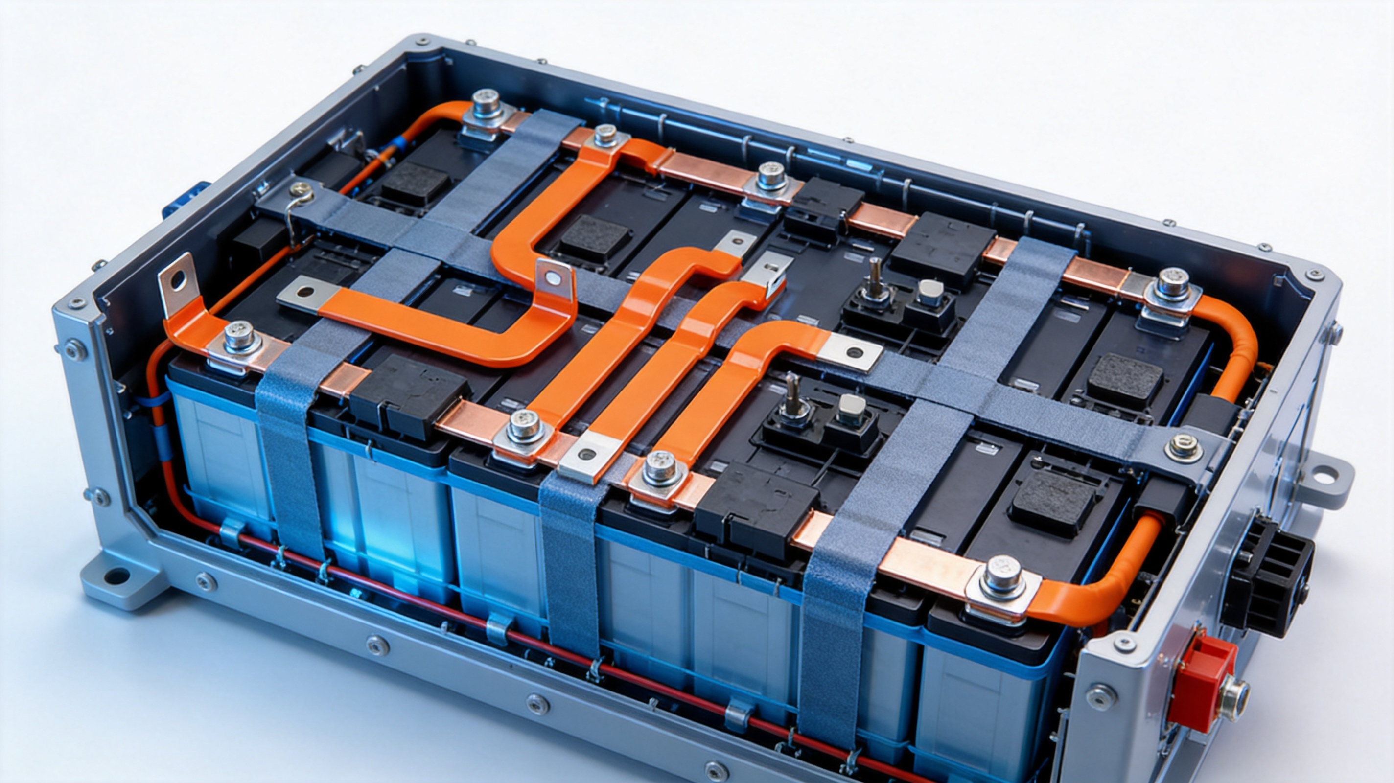
Electric vehicles, hybrid vehicles, commercial vehicles, and specialized electric transport systems contain numerous high-current connections. Battery modules must connect to one another and to busbars, contactors, fuses, inverters, charging systems, and battery-management components. These connections must fit within a limited enclosure while tolerating vibration, temperature changes, and assembly variation.
Insulated flexible busbars can be used between battery modules, at pack-level positive and negative terminals, in high-voltage distribution units, and around contactor or fuse assemblies. Their custom geometry can be matched to the pack structure, cell arrangement, cooling channels, and protective barriers.
The insulated surface helps prevent unintended contact between adjacent conductive parts. This is important in densely packed battery systems where clearance may be limited. Terminal zones can be designed for welding, crimping, bolting, or integration with other conductive components.
Automotive customers generally require strong traceability, repeatable dimensions, stable joining quality, and qualification testing. A component supplier must therefore provide more than a copper part. The supplier must understand the relationship between electrical design, mechanical packaging, manufacturing control, and vehicle-level reliability.
The company’s experience in battery soft connections and new energy conductive components supports this type of development. Its engineering and technical teams can participate in design review, sample preparation, process adjustment, and production support for battery-system customers.
12. Application in Energy Storage and LiFePO4 Systems
LiFePO4 batteries are widely used in stationary energy storage, backup power, mobile power equipment, telecommunications systems, industrial storage, and renewable-energy installations. These systems may contain multiple cells and modules connected in series or parallel. Reliable busbar design is essential for maintaining balanced current distribution and reducing unnecessary connection losses.
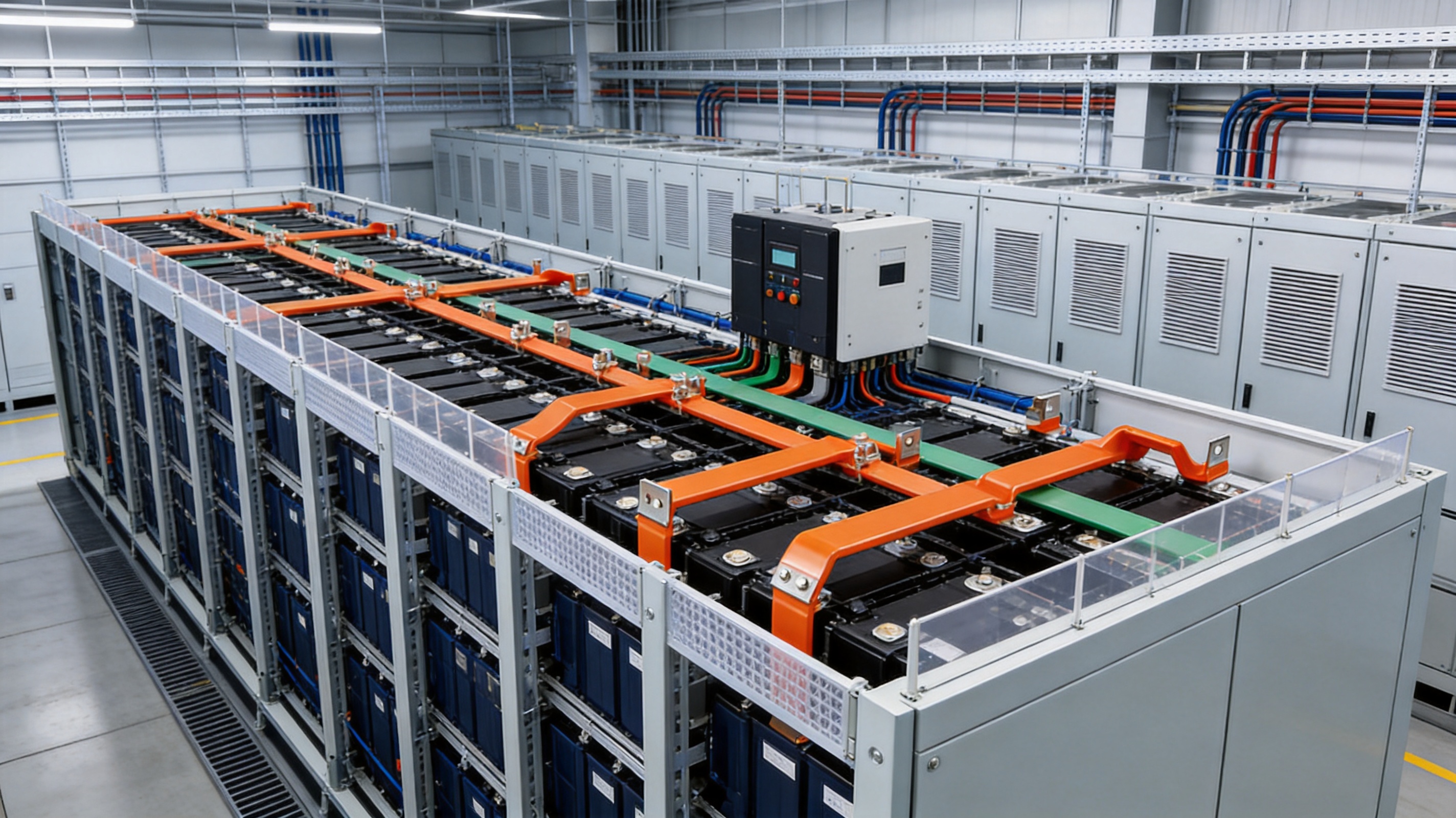
A custom LiFePO4 busbar can be designed for the dimensions of the battery enclosure, cell arrangement, terminal direction, and required current. Insulation may be applied selectively to protect the conductive path while leaving the terminal areas accessible for assembly. A hybrid rigid-flexible arrangement can simplify the connection between fixed module terminals and a larger distribution bar.
Energy-storage equipment often operates for long periods and may be exposed to temperature variation, humidity, dust, and repeated charging and discharging. The busbar therefore needs stable electrical and mechanical performance over the expected service life. The product’s temperature range, insulation options, oxidation resistance, and custom geometry can support these requirements when properly specified and tested.
For large storage cabinets, current ratings can reach high levels, particularly at the main battery and inverter connections. The conductor section area and terminal structure must be selected according to continuous and peak current requirements. The system designer should also consider fault current, short-circuit withstand, protective-device coordination, and heat dissipation.
13. Application in New Power-Grid Equipment
New power-grid systems increasingly integrate renewable generation, energy storage, electric-vehicle charging, power conversion, and intelligent distribution equipment. These systems require compact, reliable, and serviceable internal electrical connections.
Insulated flexible busbars can be used in distribution cabinets, converter assemblies, energy-storage interfaces, charging equipment, switchgear, and auxiliary power systems. Their flexible sections can simplify routing around barriers and control components. Their rigid terminal areas can align with fixed busbar supports, switch terminals, or high-current connection points.
In grid-connected equipment, electrical continuity and insulation coordination are critical. The selected busbar must be compatible with the rated voltage, operating environment, clearance, creepage, temperature rise, and short-circuit conditions of the system. The manufacturer can provide customized dimensions and materials to support these engineering requirements.
Compact busbar layouts may also help reduce cabinet size and improve internal organization. Better organization can support assembly efficiency and service access, although the final arrangement must always maintain safe clearances and adequate heat removal.
14. Additional Industrial Applications
The product can serve a wide range of high- and low-voltage electrical applications. These include industrial power supplies, vacuum electrical equipment, mining equipment, explosion-proof electrical systems, transportation equipment, communication power systems, and renewable-energy installations.
Vacuum electrical equipment may require compact conductive connections that remain stable under repeated switching or specialized environmental conditions. Mining and explosion-proof equipment may require strict attention to insulation, mechanical strength, heat management, and certification. Transportation equipment may benefit from flexible connections that tolerate vibration and restricted installation space.
Industrial customers may also use custom busbars in motor drives, rectifiers, inverters, welding equipment, battery chargers, data-center power systems, and automated production machinery. The product can be adapted to different terminal layouts and enclosure sizes, allowing the customer to avoid unnecessary cable loops or complex multi-part assemblies.
15. Engineering and Customization Process
A successful custom busbar project begins with a complete understanding of the application. The customer should provide the nominal voltage, continuous current, peak current, operating temperature, installation environment, available space, terminal dimensions, bend requirements, and expected service life.
Three-dimensional models or detailed two-dimensional drawings are useful for confirming the route and identifying interference with neighboring components. Photographs, installation samples, and assembly instructions can supplement the drawing package when the product must fit into an existing system.
The engineering team can then review conductor material, section area, insulation coverage, terminal design, welding or crimping method, and packaging requirements. If the customer is still developing the system, the manufacturer can propose alternative structures, such as a fully flexible design, a rigid-flexible hybrid, or a reinforced terminal arrangement.
After design review, a sample or pilot batch can be produced. Sample inspection should include dimensional verification, fit testing, terminal evaluation, insulation inspection, and electrical testing. Where necessary, thermal, mechanical, environmental, and life testing can be added.
Once the design is approved, production parameters can be documented for repeat manufacture. Changes to conductor size, terminal geometry, material, or insulation should be controlled through an engineering-change process. This helps ensure that the production part remains consistent with the qualified sample.
16. Quality Management and Technical Strengths
Zhejiang Zhongyan New Energy Co., Ltd. focuses on research and manufacturing of new energy conductive components. Its product scope includes high-voltage electrical copper foil soft connections, special-shaped soft connections, battery soft connections, and other precision conductive components.
The company brings together experienced engineers and technical personnel with practical knowledge of flexible connections. Its capabilities cover product design, research and development, manufacturing, and application solutions. This combination is important because high-current connectors must be designed with both electrical and mechanical factors in mind.
The company uses modern production and quality-management systems to support product consistency. Advanced professional equipment and digital processing technology help standardize production parameters and reduce variation across repeated orders.
Since its establishment in 2022, the company has concentrated on precision components for new energy applications, including battery soft connections. It has developed polymer diffusion welding and laser-technology capabilities intended to support low internal resistance and high connection reliability. These technologies can be considered when a customer requires specialized joining or a compact conductive interface.
The company is also developing an integrated research and development system covering materials science, precision machining, testing, and verification. This broader technical direction supports the development of battery cells, connection systems, and integrated energy-storage solutions.
For OEM customers, an important advantage is the ability to communicate with a supplier that understands custom design, material selection, manufacturing engineering, and application verification. This can reduce the need to coordinate separate suppliers for the conductor, terminal, insulation, and joining process.
17. Product Selection Guidelines
When selecting an insulated flexible busbar, the first consideration should be the electrical load. The designer should identify continuous current, peak current, duty cycle, overload duration, voltage, and fault conditions. Current rating should not be determined from conductor section area alone because temperature rise depends on the complete installation.
The second consideration is mechanical geometry. The required length, bend direction, bend radius, terminal position, hole spacing, and support points should be defined before production. The route should avoid sharp folds and should provide sufficient space for installation and inspection.
The third consideration is insulation. The insulation material, thickness, coverage, color, voltage rating, temperature range, and environmental resistance should match the application. Halogen-free material may be preferred where fire behavior, environmental policy, or customer specifications require it.
The fourth consideration is the terminal connection. Welding, crimping, bolting, or a combination may be selected. The choice depends on serviceability, available equipment, terminal material, mechanical stress, production volume, and electrical requirements.
The fifth consideration is environmental exposure. Temperature, humidity, vibration, dust, chemicals, salt, condensation, and mechanical impact should be identified. Qualification testing can then be designed around realistic use conditions.
Finally, the customer should consider supply consistency, traceability, packaging, and change control. A high-quality component is valuable only when it can be delivered repeatedly with stable performance and clear documentation.
18. Installation and Handling Recommendations
Insulated flexible busbars should be handled carefully to prevent scratches, cuts, excessive bending, or contamination of terminal surfaces. The product should be stored in a clean, dry environment and protected from moisture and mechanical impact before installation.
During assembly, the flexible section should be routed according to the approved drawing. It should not be twisted beyond the intended design or forced against sharp edges. If the assembly requires a minimum bend radius, that requirement should be clearly defined and maintained.
Terminal surfaces should be clean and compatible with the selected joining method. For welded connections, surface condition, weld parameters, and fixture alignment should be controlled. For crimped connections, the correct tooling, terminal position, crimp height, and conductor insertion should be verified.
Fasteners, if used, should be tightened according to the specified torque. Excessive torque may damage the terminal or connected component, while insufficient torque may increase contact resistance or allow movement. After installation, the assembly should be inspected for clearance, insulation damage, contact with sharp edges, and correct orientation.
Where the busbar is used in a high-voltage system, appropriate electrical safety procedures must be followed. Insulation resistance and withstand-voltage tests should be conducted according to the approved test plan, and the completed assembly should be checked before energization.
19. Frequently Asked Questions
What is an insulated flexible busbar?
An insulated flexible busbar is a conductive copper connection designed to carry electrical current while allowing controlled flexibility. An insulating layer covers part or most of the conductor to provide electrical separation and protection. The product can include rigid terminal areas and may be customized for battery, industrial, automotive, or power-grid applications.
Why is T2 copper used?
T2 copper offers good electrical conductivity, ductility, and forming performance. These characteristics make it suitable for high-current conductive parts that must also be cut, formed, welded, or otherwise processed into a customized geometry.
Can the busbar be used in LiFePO4 battery systems?
Yes. The busbar can be designed for LiFePO4 battery packs and energy-storage systems when its current rating, voltage, insulation, terminal configuration, temperature range, and environmental resistance are correctly specified for the application.
What is the advantage of combining rigid and flexible sections?
The flexible section helps accommodate routing variation, vibration, and thermal movement, while the rigid section provides a stable terminal or mounting interface. This hybrid structure can simplify installation and reduce mechanical stress compared with an entirely rigid busbar.
What current ratings are available?
Typical product information covers current ratings from approximately 50 A to 2500 A. The suitable rating depends on conductor section area, ambient temperature, cooling conditions, duty cycle, insulation design, terminal construction, and the customer’s required temperature rise.
What section areas are available?
Typical section areas range from approximately 10 mm² to 1200 mm². Custom dimensions can be evaluated according to current requirements, available space, mechanical design, and manufacturing feasibility.
Can the product use halogen-free insulation?
Yes. A halogen-free insulating material is available as an option. This may support projects that address RoHS requirements, IEC 60754-related emission considerations, and reduced corrosive or toxic gas concerns during fire conditions. The exact material and compliance documentation should be confirmed for each project.
Are welded and crimped terminals available?
Yes. The product can be designed with welded or crimped terminals. The preferred connection method depends on the equipment structure, production process, service requirements, electrical performance, and mechanical conditions.
Can the busbar be made for a customer’s drawing?
Yes. Custom design is a central feature of the product. Customers can provide drawings, three-dimensional models, terminal specifications, current requirements, and installation information for engineering review and sample development.
How does digital processing improve the product?
Digital processing helps standardize cutting, forming, terminal preparation, welding, and other manufacturing parameters. It can improve dimensional repeatability, support engineering changes, and create a more consistent basis for mass production.
What industries can use this product?
Potential industries include electric and hybrid vehicles, LiFePO4 energy storage, renewable energy, charging equipment, power grids, industrial power supplies, transportation, communications, mining, vacuum electrical equipment, and other high-current electrical systems.
How should the correct busbar be selected?
The selection should consider current, voltage, section area, temperature, insulation, bend geometry, terminal method, environmental exposure, fault conditions, and installation space. A complete application specification allows the manufacturer to recommend a suitable structure and validation plan.
20. Conclusion
Insulated flexible busbars provide a practical connection solution for the increasingly compact and demanding electrical systems used in automotive batteries, LiFePO4 energy storage, new power grids, industrial equipment, and transportation. By combining T2 copper conductivity, controlled flexibility, engineered insulation, customizable terminal structures, and digital manufacturing, the product can address requirements that are difficult to satisfy with a standard rigid bar or conventional cable assembly.
The main advantages include efficient current transmission, flexible routing, high heat-dissipation potential, oxidation resistance, halogen-free insulation options, and compatibility with welded or crimped terminals. A hybrid design can combine rigid mounting accuracy with the stress-relief benefits of a flexible conductor. These features are especially valuable in battery packs and high-voltage distribution systems where space, reliability, safety, and assembly efficiency are closely connected.
Zhejiang Zhongyan New Energy Co., Ltd. supports this product category with experience in battery soft connections, high-voltage copper foil connections, special-shaped flexible components, precision processing, polymer diffusion welding, laser technology, and new energy applications. Its engineering and manufacturing capabilities allow it to work with OEMs and system integrators from initial design through sample approval and repeat production.
For customers seeking a custom copper busbar supplier, the most effective approach is to define electrical, mechanical, thermal, environmental, and manufacturing requirements at the beginning of the project. With a complete specification and controlled development process, an insulated flexible busbar can become a reliable part of the battery, power-distribution, or energy-storage system rather than simply a replacement for a conventional cable.
References
1. IEC 60754, Tests on Gases Evolved During Combustion of Materials from Cables.
2. IEC 60664, Insulation Coordination for Equipment Within Low-Voltage Systems.
3. IEC 60947, Low-Voltage Switchgear and Controlgear.
4. UL 94, Standard for Tests for Flammability of Plastic Materials for Parts in Devices and Appliances.
5. Restriction of Hazardous Substances Directive, RoHS Compliance Framework.
6. Copper Development Association, Copper Electrical Conductivity and Engineering Applications.
7. International Electrotechnical Commission, Guidance on Electrical Connections, Temperature Rise, and Insulation Performance.
8. Automotive and Stationary Energy-Storage Engineering Practices for High-Voltage Battery Interconnections.
Product: Automotive Batteries New Energy Power Grids Flexible Connector

Driven by the development of new energy and aiming for "zero carbon".
Copyright © Zhejiang Zhongyan New Energy Co., Ltd. All Rights Reserved.
