 English
 Español

Inverter Composite Laminated Busbar: Precision Power Distribution for High-Performance Systems
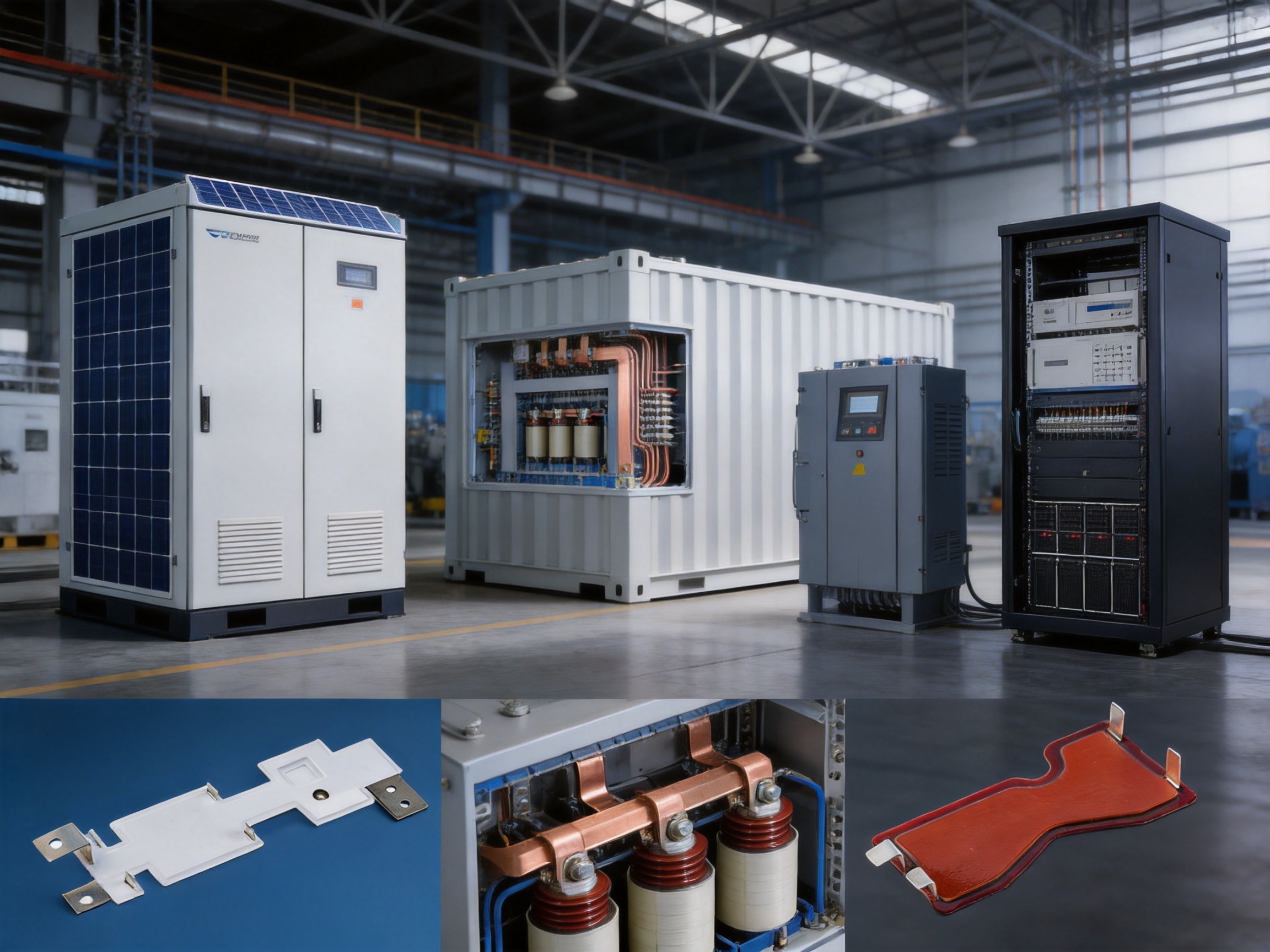
Modern power-conversion equipment demands more than simple electrical conductivity. Inverters, renewable-energy converters, industrial drives, railway systems, communication infrastructure, and energy-storage equipment must manage high current, elevated voltage, thermal cycling, vibration, limited installation space, and strict insulation requirements at the same time. A conventional collection of cables and separate copper links can perform these functions, but it often introduces unnecessary resistance, complicated assembly, electromagnetic interference, uneven current distribution, and increased maintenance requirements.
The inverter composite laminated busbar is engineered to address these challenges through a compact, layered, and application-specific electrical interconnection structure. By integrating conductive plates, insulation materials, mounting features, and terminal interfaces into one coordinated component, the laminated busbar creates a more controlled path for power distribution. It can simplify inverter architecture while helping equipment designers achieve improved space utilization, repeatable electrical performance, and more reliable insulation coordination.
Custom manufacturing is particularly important because inverter systems differ significantly in voltage class, current rating, mechanical envelope, terminal arrangement, cooling strategy, and installation environment. A laminated busbar intended for a 600 V DC, 1,200 A application may require a completely different conductor thickness and layout from a 1,900 V DC, 200 A busbar. The product range described in this article demonstrates how custom dimensions, copper thicknesses, surface finishes, and electrical ratings can be matched to different power-conversion requirements.
Zhejiang Zhongyan New Energy Co., Ltd. provides customized conductive components and precision connection solutions for power distribution, new energy vehicles, rail transportation, communication systems, and energy storage applications. Its engineering background in high-voltage copper foil flexible connections, battery soft connections, special-shaped conductive components, and precision manufacturing provides a strong foundation for developing reliable laminated busbars and related electrical assemblies.
Content
- What Is an Inverter Composite Laminated Busbar?
- Why Laminated Busbars Are Important in Inverter Systems
- Core Product Advantages
- Representative Technical Configurations
- Surface Plating and Contact Reliability
- Engineering Design Process
- Advanced Manufacturing Capabilities
- Manufacturing Strengths of the Supplier
- Advantages Compared with Conventional Connection Methods
- Application Fields
- Quality, Reliability, and Traceability
- How to Specify a Custom Laminated Busbar
- Installation and Application Considerations
- Future Development of Laminated Busbar Technology
- Frequently Asked Questions
- What is the main purpose of an inverter laminated busbar?
- Can the busbar be customized for different voltage and current ratings?
- What materials are used for the conductive layers?
- Why is tin plating used on some busbars?
- What dielectric test is available for the listed configurations?
- Can a laminated busbar replace all cables in an inverter?
- How does a laminated busbar help reduce electromagnetic interference?
- What information is needed for a quotation?
- Does the manufacturer provide more than laminated busbars?
- How should the finished busbar be tested?
- Conclusion
- References
- Product: Inverter Composite Laminated Busbar
What Is an Inverter Composite Laminated Busbar?
An inverter composite laminated busbar is a multi-layer electrical conductor designed to distribute direct current or alternating current within power-electronic equipment. The primary conductive layers are generally made from copper or another suitable conductive metal. These layers are separated and supported by insulating material, while the entire assembly is shaped to match the equipment’s electrical and mechanical requirements.
Unlike a basic flat copper bar, a composite laminated busbar is not merely a strip of metal. It is an integrated electrical and mechanical assembly. Its design may include multiple conductive plates, dielectric films, insulating sheets, plated terminal areas, mounting holes, perforated sections, stepped profiles, and customized connection points. The final geometry is developed around the inverter’s semiconductor modules, capacitors, reactor, cooling system, enclosure, and external terminals.
The laminated configuration allows positive and negative conductors, or different phases, to be arranged in a controlled and compact relationship. This can reduce the loop area of the current path, which is particularly valuable in high-frequency switching circuits. A smaller loop area can contribute to lower parasitic inductance and more predictable switching behavior, subject to the complete system design and validation process.
The composite structure also helps separate conductive layers from one another. Proper insulation design is essential in systems operating at 600 V, 1,200 V, 1,900 V, or higher transient levels. The insulation system must be selected and processed according to voltage, temperature, creepage distance, clearance, mechanical stress, contamination conditions, and the required dielectric-strength test.
Why Laminated Busbars Are Important in Inverter Systems
Inverters convert electrical energy from one form to another. For example, they may convert DC power from a battery or photovoltaic array into AC power for a motor, grid connection, or industrial load. During this conversion, high currents can flow through semiconductor switching devices, capacitors, filters, and output terminals. The interconnection between these components must carry power efficiently while maintaining controlled electrical behavior.
A poorly designed connection system can create several problems. Long cables may increase resistance and voltage drop. Flexible cable loops may occupy valuable enclosure space. Different cable lengths can create unequal current sharing in parallel paths. Uncontrolled conductor spacing can increase electromagnetic coupling. Numerous lugs, washers, and fasteners can add assembly variation and potential points of failure.
A laminated busbar provides a more organized alternative. The conductor layout is established during the design and fabrication stage rather than being created during final equipment assembly. Connection points can be positioned precisely, and the insulation structure can be integrated into the component. This supports a cleaner internal layout and can reduce the number of separate parts required by the inverter manufacturer.
Another important benefit is repeatability. When the same busbar geometry is produced consistently, inverter assembly teams can install the component using a defined process. This can improve production efficiency and reduce variation between units. For high-volume products, repeatable busbar geometry may also support automated or semi-automated assembly, inspection, and electrical testing.
Core Product Advantages
Compact and Space-Efficient Design
Inverter manufacturers are continually seeking higher power density. Equipment must deliver more power while occupying less cabinet, rack, vehicle, or container space. A laminated busbar can follow the available three-dimensional installation envelope and place terminals close to the components they serve.
Compared with separate cables and conventional busbars, the integrated structure can reduce unused routing space. This may allow capacitors, power modules, contactors, fuses, and service disconnects to be positioned more efficiently. The resulting assembly can be cleaner and easier to inspect because the power path is clearly defined.
Compactness is especially valuable in mobile applications. Public-transit vehicles, railway equipment, marine propulsion systems, electric heavy machinery, and industrial vehicles face strict limitations on weight and cabinet volume. A shaped laminated busbar can support a shorter and more direct connection between high-power components without the bulk associated with multiple cable runs.
Low-Resistance Current Paths
Copper offers excellent electrical conductivity and is widely used for high-current busbar applications. The conductor thickness, width, plating, bend geometry, and contact area are selected according to the required current and thermal conditions. A properly designed laminated structure can provide a broad, low-resistance path compared with undersized or excessively long cable arrangements.
Lower resistance helps reduce I²R losses and unwanted heat generation. In a high-current inverter, even a small reduction in resistance can influence efficiency and thermal-management requirements. The actual performance depends on conductor dimensions, joint quality, operating temperature, current waveform, duty cycle, ventilation, and the complete installation method.
The product configurations supplied for different applications include copper plate thicknesses of approximately 2.0 mm, 2.5 mm, 3.0 mm, and 4.0 mm. These options demonstrate the importance of matching conductor construction to the required current rating rather than using a single standard geometry for every project.
Controlled Parasitic Inductance
Fast-switching semiconductor devices can be sensitive to stray inductance in the DC link and commutation loop. Excessive inductance may contribute to voltage overshoot, ringing, electromagnetic interference, and additional stress on switching devices. While the final circuit performance depends on the complete inverter topology, the physical arrangement of the busbar has an important influence on the current loop.
By placing related conductors in a compact laminated arrangement, the forward and return current paths can be positioned close together. This may reduce the loop area and help control parasitic inductance. The design can also provide a more consistent electrical path than separately routed cables with variable spacing.
For demanding inverter designs, the busbar should be developed together with the power module, DC-link capacitor, switching frequency, current waveform, gate-drive strategy, and electromagnetic-compatibility requirements. Early cooperation between the equipment designer and the busbar manufacturer is therefore essential.
Improved Insulation Organization
The insulating layers in a composite busbar create separation between conductive elements and support electrical safety. They can also help protect the conductor surfaces from accidental contact, assembly damage, and contamination during normal use.
Insulation design must consider more than nominal operating voltage. Transient overvoltage, switching peaks, pollution level, altitude, humidity, temperature, mechanical movement, and material aging can influence the required insulation system. Clearance and creepage distances must be verified according to the applicable product and system standards.
The supplied product data includes dielectric-strength testing at 5 kV DC for 60 seconds with leakage below 2 mA for the listed configurations. This test value indicates a high-voltage withstand requirement for the finished assembly. It should not be interpreted as a universal operating voltage or as a substitute for project-specific insulation coordination and certification.
Reliable Mechanical Integration
A laminated busbar performs both electrical and mechanical functions. Its mounting holes, perforations, bends, terminal platforms, and support areas must align accurately with the inverter enclosure and internal components. Dimensional consistency is therefore critical.
Incorrect hole positions or uncontrolled flatness can cause installation stress. Excessive stress may affect terminal joints, insulation layers, or semiconductor-module connections. Precision fabrication helps ensure that the busbar fits the intended assembly without forcing components into position or requiring unplanned modifications during production.
The available examples include rectangular and irregularly proportioned assemblies with dimensions such as 453 mm × 221 mm, 480 mm × 316 mm, 420 mm × 147 mm, 237 mm × 225 mm, and 282 mm × 237 mm. These dimensions illustrate that laminated busbars are commonly designed as equipment-specific components rather than generic off-the-shelf strips.
Reduced Assembly Complexity
Traditional power distribution assemblies may include numerous cables, lugs, insulating barriers, spacers, bolts, and separate busbars. Each additional part increases the number of assembly operations and inspection points. A customized laminated busbar can consolidate several of these functions into one engineered component.
Reducing part count can shorten installation time and make the power path easier to understand. It can also simplify service work because technicians can identify terminals and mounting locations more easily. The exact reduction depends on the original architecture, but the general principle is to replace multiple individually installed conductors with a coordinated assembly.
For manufacturers producing repeat inverter models, this integration can also improve process control. The busbar can be inspected as a finished subassembly before installation, allowing defects to be identified earlier in the production flow.
Representative Technical Configurations
The following configurations are examples of product specifications provided for inverter composite laminated busbars. Final ratings should be confirmed through electrical, thermal, mechanical, and insulation validation for the intended application.
| Configuration | Dimensions | Conductor Construction | Voltage | Current | Dielectric Strength |
| A | 453 mm × 221 mm | 2.5 mm perforated plate, tin-plated surface | 1,900 V DC | 200 A | 5 kV DC for 60 seconds, below 2 mA |
| B | 480 mm × 316 mm | 2.0 mm copper plate, plated surface | 600 V DC | 1,200 A | 5 kV DC for 60 seconds, below 2 mA |
| C | 480 mm × 316 mm | 3.0 mm copper plate, tin-plated surface | 1,200 V DC | 500 A | 5 kV DC for 60 seconds, below 2 mA |
| D | 420 mm × 147 mm | 2.5 mm copper plate, plated surface | 1,900 V DC | 400 A | 5 kV DC for 60 seconds, below 2 mA |
| E | 237 mm × 225 mm | 3.0 mm copper plate, plated surface | 1,900 V DC | 400 A | 5 kV DC for 60 seconds, below 2 mA |
| F | 282 mm × 237 mm | 4.0 mm copper plate, tin-plated surface | 600 V DC | 300 A | 5 kV DC for 60 seconds, below 2 mA |
These configurations cover a broad combination of voltage, current, dimensions, and conductor thickness. The 1,200 A configuration demonstrates the suitability of the product concept for high-current low-voltage DC systems. The 1,900 V DC configurations demonstrate the need for careful insulation engineering in higher-voltage inverter applications. The different copper thicknesses show how conductor capacity and mechanical construction can be adapted to the application.
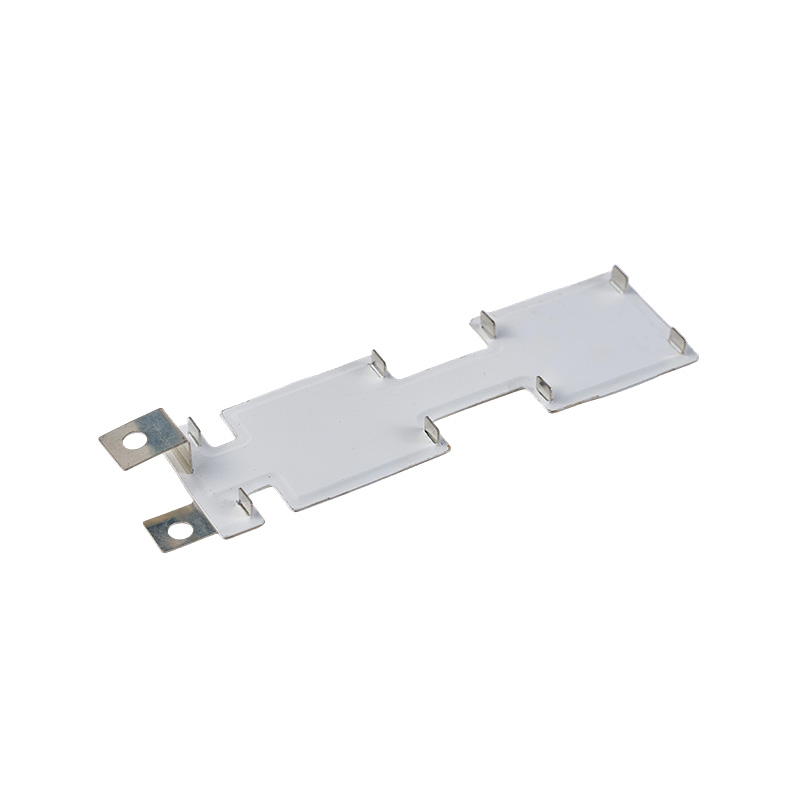
Inverter Composite Laminated Busbar
Surface Plating and Contact Reliability
Surface plating is selected according to the required electrical, environmental, and mechanical performance. Tin plating is commonly used to improve surface stability and support reliable bolted or clamped electrical connections. A plated surface can also help reduce the effects of oxidation and support consistent contact behavior when properly prepared and assembled.
In a busbar system, the quality of the contact interface is as important as the conductivity of the bulk copper. Contact areas must be sufficiently flat, clean, and properly finished. Fastener torque, joint pressure, contact area, washer selection, and service temperature all influence long-term connection performance.
The product examples include both tin-plated surfaces and other plated copper surfaces. The appropriate finish may depend on the customer’s terminal material, environmental conditions, assembly method, expected service life, and applicable specifications. For projects exposed to humidity, salt spray, chemical contamination, or temperature cycling, surface-finish selection should be addressed during the design stage.
Plating must also be controlled around holes, edges, bends, and terminal transitions. Poor edge treatment can create burrs or localized stress, while inconsistent plating may affect joint quality. A mature manufacturing process includes inspection of the relevant surfaces rather than relying only on a visual check of the overall assembly.
Engineering Design Process
Requirement Definition
The first step in producing a custom laminated busbar is to define the complete electrical and mechanical requirement. Important inputs include nominal voltage, maximum continuous current, overload current, switching frequency, ambient temperature, allowable temperature rise, short-circuit conditions, insulation level, installation altitude, enclosure dimensions, terminal locations, and expected service life.
The customer should also provide the positions of power modules, capacitors, contactors, fuses, current sensors, cooling channels, and enclosure fixing points. Three-dimensional CAD data is useful because laminated busbars often need to pass around mechanical obstructions and connect components located on different planes.
Electrical Layout
The conductive layers are arranged to achieve the required current capacity and connection sequence. The design team considers conductor width, thickness, parallel paths, terminal area, current concentration, bend radius, and the distance between different potentials.
In high-frequency inverter circuits, the commutation loop and DC-link path deserve special attention. The design may place positive and negative conductors in adjacent layers to reduce loop area. In multi-phase systems, the phase conductors may be arranged to control coupling and maintain balanced connection geometry.
Electrical simulation and engineering calculations can support the design process. However, calculations should be confirmed by prototype testing because contact resistance, assembly tolerances, thermal conditions, and material behavior can influence the real performance of the completed assembly.
Insulation and Dielectric Design
The insulation structure is selected according to the voltage class and environment. Engineers evaluate dielectric strength, thermal class, thickness, flexibility, adhesion, resistance to vibration, and compatibility with the conductor and manufacturing process.
Clearance is the shortest distance through air between conductive parts at different potentials. Creepage is the shortest distance along an insulating surface. Both must be sufficient for the application, and their requirements can change with pollution degree, altitude, material group, and working voltage.
Edges, holes, slots, and terminal transitions require particular attention because they can reduce effective insulation distance or create concentrated electric fields. Rounded edges, controlled insulation overlap, and carefully positioned perforations can improve the robustness of the finished design.
Mechanical and Thermal Validation
The busbar must withstand installation forces, vibration, thermal expansion, and service loading. Copper and insulation materials have different coefficients of thermal expansion. Repeated temperature changes can therefore create mechanical stress between layers or at fixed connection points.
Thermal validation considers current density, conductor thickness, exposed surface area, ambient temperature, airflow, cooling plates, enclosure conditions, and neighboring heat sources. A busbar that performs well in an open laboratory environment may require additional analysis when installed in a compact sealed inverter enclosure.
Prototype testing may include temperature-rise tests, dielectric-strength tests, insulation-resistance tests, mechanical fit checks, vibration testing, thermal cycling, and visual inspection after environmental exposure. The exact test plan should be based on the end product, customer requirements, and relevant industry standards.
Advanced Manufacturing Capabilities
The quality of a laminated busbar depends on the coordination of material preparation, precision machining, plating, insulation processing, assembly, and testing. A manufacturer with experience in high-voltage conductive components can address these operations as an integrated production system rather than treating each stage as an isolated subcontracting task.
Precision Material Preparation
Copper sheet and plate must be received, identified, stored, and prepared in a way that protects their surface condition. Material thickness, flatness, conductivity, and cleanliness influence the final product. Controlled material handling helps prevent scratches, contamination, and unintended deformation before machining.
For custom designs, material preparation may include cutting blanks, separating conductor layers, preparing perforated sections, and defining terminal areas. The process must preserve the dimensional relationships required for later insulation and assembly operations.
Precision Machining and Forming
Machining operations may include cutting, punching, drilling, slotting, bending, and edge treatment. Dimensional accuracy is important because the busbar must align with inverter components and enclosure features. Burr control is also essential. A sharp burr can damage insulation, reduce clearance, or create an unintended concentration of electrical stress.
Forming operations must maintain the designed bend angle, radius, and flatness. Excessive forming force can deform holes or distort terminal surfaces. Controlled tooling and inspection help ensure that each production batch maintains the intended geometry.
Plating and Surface Treatment
After machining and cleaning, conductive surfaces may receive tin plating or another specified finish. Surface preparation before plating is important because oils, oxides, and particles can affect adhesion and uniformity. Plating thickness and coverage should be controlled according to the application requirement.
Contact areas may require specific masking or finishing so that the final interface is suitable for bolted, clamped, welded, or assembled connections. The manufacturer’s ability to coordinate machining and surface treatment can reduce the risk of mismatch between the drawing and the finished product.
Insulation Lamination and Assembly
Lamination brings conductive layers and insulating materials together in the designed sequence. The process must control alignment, pressure, temperature, bonding conditions, and cleanliness. Voids, wrinkles, foreign particles, or misalignment can affect dielectric performance and mechanical stability.
Perforated plates and mounting features require special control because holes can influence insulation distance and create local mechanical stress. The production process should verify that insulation remains properly positioned around these features.
Where the design includes additional conductive joints or flexible connection sections, specialized joining techniques may be used. Zhejiang Zhongyan New Energy has developed capabilities in polymer diffusion welding and laser technology for high-reliability conductive components. These capabilities are especially relevant to the company’s broader portfolio of high-voltage copper-foil soft connections, battery connections, and precision energy-storage components.
Inspection and Electrical Testing
Inspection may include dimensional measurement, visual examination, plating verification, insulation inspection, terminal flatness measurement, and electrical testing. The specific quality plan should be agreed with the customer before production begins.
Dielectric-strength testing is a key verification step for high-voltage laminated busbars. The listed examples are tested at 5 kV DC for 60 seconds with leakage below 2 mA. Insulation resistance and continuity checks can provide additional information about the condition of the assembly.
Test records can support traceability and help customers establish confidence in the manufacturing process. For regulated or safety-critical industries, documentation may include material certificates, inspection reports, process records, test results, and approved drawings.
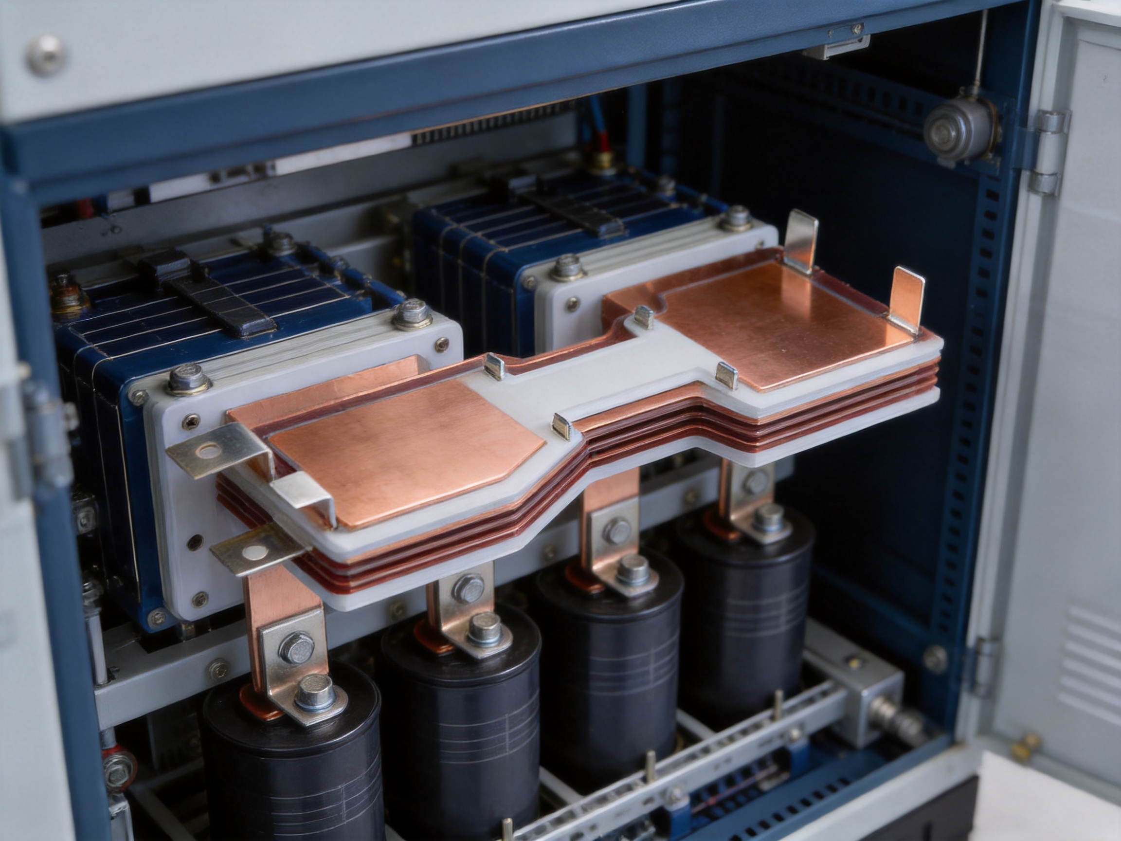
Manufacturing Strengths of the Supplier
Zhejiang Zhongyan New Energy Co., Ltd. was established in 2022 as a high-tech enterprise focused on new-energy conductive components and precision electrical connection solutions. Although its development history is relatively recent, the company emphasizes engineering capability, specialized equipment, modern quality-management practices, and application-oriented product development.
Its product and technology scope includes high-voltage electrical copper-foil soft connections, special-shaped soft connections, battery soft connections, and other precision conductive components. These products serve demanding industries where low internal resistance, reliable joining, dimensional consistency, and long service life are important.
The company brings together experienced engineers and technical personnel covering product design, research and development, manufacturing, testing, and verification. This multidisciplinary structure is valuable for laminated busbar projects because the product must satisfy electrical, thermal, mechanical, insulation, and production requirements simultaneously.
The company also reports experience serving leading enterprises, including BYD, CATL, and Jaguar. Such customer exposure indicates experience with demanding quality expectations and new-energy applications. Specific project performance, qualification status, and production scope should be confirmed for each customer program, but the background supports the company’s position as a specialized supplier of precision conductive components.
In addition to current conductive-component manufacturing, the company is developing an integrated innovation system covering materials science, precision machining, testing, and verification. Its research direction includes battery cells, connection systems, lithium battery manufacturing, and integrated cell-and-connection-system design. This broader technical direction can help the manufacturer understand how a laminated busbar interacts with batteries, power modules, energy-storage systems, and complete electrical architectures.
Advantages Compared with Conventional Connection Methods
Compared with Cable Harnesses
Cable harnesses are flexible and practical for many applications, but high-current inverter systems can require multiple parallel cables, additional insulation, large bending radii, and numerous termination components. Cable routing can also become difficult when terminals are close together or when the enclosure is densely packed.
A laminated busbar provides a predefined geometric path. It can reduce routing complexity and make the internal power architecture more compact. Its performance is more repeatable because conductor spacing, length, and terminal positions are controlled during fabrication.
Cables may remain preferable where flexibility, frequent movement, or long-distance routing is required. The correct choice depends on the system. A laminated busbar is particularly attractive for fixed internal inverter connections where high current, compactness, and controlled electrical behavior are priorities.
Compared with Separate Flat Busbars
Separate flat busbars can provide excellent conductivity, but they may require independent spacers, barriers, protective sheets, and mounting hardware. Their installation can involve several alignment operations, and insulation coordination may be more difficult when multiple conductors are assembled individually.
A composite laminated busbar combines these elements into a coordinated structure. It can create a more consistent relationship between conductor layers and insulation. This can simplify installation and reduce the possibility of an assembly worker placing a spacer or barrier incorrectly.
Compared with Generic Standard Parts
Generic busbars are useful when the equipment architecture is standardized and the available dimensions match the application. However, inverter systems often have unique terminal layouts, cooling arrangements, and enclosure dimensions. A generic component may require adapters, additional links, or manual modifications.
Custom laminated busbars are developed around the equipment. The supplier can adapt dimensions, conductor thickness, plating, terminal position, hole patterns, insulation arrangement, and current rating to the customer’s design. This reduces compromises and allows the busbar to become part of the inverter’s original architecture rather than an afterthought.
Application Fields
Renewable-Energy Inverters
Wind-power converters and high-power photovoltaic grid-connected converters require efficient and reliable power distribution between rectifier stages, DC links, switching modules, filters, and grid-interface equipment. Laminated busbars can support compact power-conversion cabinets and help establish controlled connection paths for high-voltage DC circuits.
Renewable-energy equipment often operates in environments with temperature variation, humidity, dust, vibration, and demanding service schedules. The busbar design should therefore consider thermal cycling, enclosure protection, maintenance access, and long-term insulation performance.
Communication Infrastructure
Large telecommunications switching systems, mobile-phone base stations, ADSL racks, and data-storage servers require dependable power distribution within restricted rack or cabinet spaces. Laminated busbars can support high-density DC power distribution and provide organized connections between rectifiers, battery systems, backup units, and load equipment.
In communication infrastructure, uptime and serviceability are important. A clearly organized busbar assembly can simplify inspection and reduce the number of loose cable paths. The design should account for redundant power paths, service disconnects, monitoring circuits, and the thermal conditions inside the rack.
Ground Transportation and Marine Propulsion
Public-transit vehicles, railway equipment, marine propulsion systems, and heavy machinery place demanding requirements on electrical connections. These systems may experience vibration, shock, repeated acceleration and braking, temperature changes, and restricted installation space.
Laminated busbars can be used in propulsion converters and related power-conversion equipment where voltage, current, partial-discharge behavior, and mechanical robustness must be controlled. Railway auxiliary converters may use such components for air-conditioning, lighting, traction-support, and other onboard electrical functions.
Computers and Office Equipment
High-performance computing and office infrastructure increasingly require efficient power delivery in compact cabinets. Laminated busbars can help organize connections in power-supply systems, UPS equipment, server power shelves, and related distribution assemblies.
Although current levels vary widely in this field, the same principles apply: compact construction, predictable impedance, reduced wiring complexity, and reliable insulation. The final design must be adapted to rack dimensions, airflow, service access, and redundancy requirements.
Industrial Equipment
Industrial applications include uninterruptible power supplies, welding machines, medical equipment, elevator drive systems, motor drives, automation cabinets, and high-power control equipment. These products can involve high inrush currents, high-frequency switching, frequent operating cycles, and strict requirements for electrical safety.
A custom laminated busbar can support the internal connection between rectifiers, capacitors, semiconductor modules, reactors, output terminals, and protective devices. It may also reduce assembly time for equipment produced in repeated configurations.
Aerospace and Defense
Aerospace and defense equipment generally places strong emphasis on weight, reliability, vibration resistance, electrical safety, and traceable manufacturing. Laminated busbars can support compact power-conversion assemblies where controlled geometry and reduced interconnection complexity are valuable.
Projects in this field may require special materials, documentation, environmental testing, and qualification procedures. The manufacturer and customer must define the applicable standards and acceptance requirements before production.
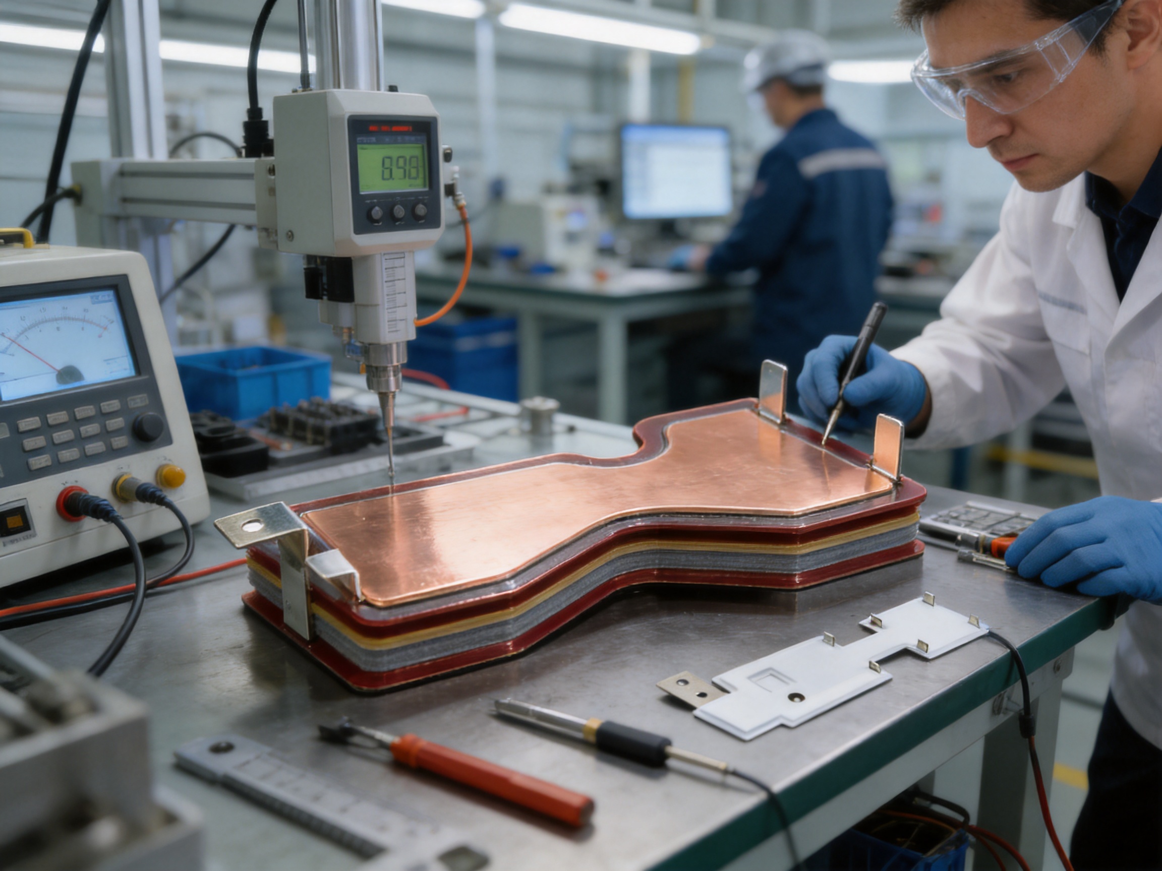
Quality, Reliability, and Traceability
Reliable busbar performance begins with a controlled specification. Drawings should define conductor material, thickness, dimensions, tolerances, surface finish, insulation materials, test voltage, terminal requirements, and any special environmental conditions. Ambiguous requirements can lead to inconsistent interpretation during production.
Process control should continue through material receipt, cutting, forming, plating, insulation assembly, inspection, and final testing. Each stage has potential effects on electrical or mechanical performance. For example, a small burr created during punching can damage insulation, while an apparently minor distortion of a terminal surface can increase contact resistance.
Traceability is especially important for high-voltage and high-current components. Material batches, plating records, inspection results, and dielectric-test data can help identify the production history of each lot or assembly. This information supports customer audits, failure analysis, and continuous improvement.
Quality control should not be limited to final testing. Final testing can identify a problem, but process monitoring helps prevent the problem from occurring. A mature system therefore combines incoming inspection, in-process checks, operator controls, equipment maintenance, statistical monitoring where appropriate, and final verification.
How to Specify a Custom Laminated Busbar
Customers requesting a quotation should provide as much information as possible. A complete specification reduces development time and helps the supplier recommend an appropriate structure.
The basic electrical information should include DC or AC voltage, continuous current, peak current, overload duration, switching frequency, fault-current conditions, allowable voltage drop, and maximum temperature rise. If current is pulsed or highly dynamic, the waveform and duty cycle should also be provided.
The mechanical information should include overall envelope, mounting-hole positions, terminal coordinates, conductor orientation, bend requirements, enclosure restrictions, service-access requirements, and the location of surrounding components. Three-dimensional models and two-dimensional drawings are both useful.
The insulation information should include working voltage, test voltage, insulation-resistance requirement, clearance, creepage, pollution level, altitude, environmental conditions, and any partial-discharge requirement. If the equipment must comply with a particular standard, that standard should be identified at the beginning of the project.
The material and surface-finish information should include copper grade, conductor thickness, plating type, plating area, terminal finish, and any requirement for corrosion resistance or solderability. If the busbar connects to aluminum, plated terminals, flexible copper foil, or another dissimilar material, the joint design should be reviewed carefully.
Finally, the customer should define production quantity, prototype requirements, annual demand, packaging needs, inspection documentation, and delivery expectations. A manufacturer can then evaluate tooling, process selection, testing, and cost more accurately.
Installation and Application Considerations
Even a well-manufactured busbar can underperform if it is installed incorrectly. Installation personnel should follow the approved drawing and assembly instructions. Terminal surfaces must be clean and free from damage. Fasteners should be tightened to the specified torque using suitable tools.
Insulation must not be pierced, folded, or compressed beyond the approved design. Unintended contact with enclosure edges or neighboring conductors should be prevented. If the busbar includes protective films or temporary packaging materials, they should be removed only as specified by the assembly procedure.
Thermal expansion should be considered where the busbar is connected to components made from different materials. Mounting points may need to accommodate movement without placing excessive stress on terminals or insulation layers.
After installation, electrical continuity, insulation resistance, dielectric strength, terminal torque, and mechanical clearance should be checked according to the equipment’s quality plan. Any modification to the busbar, such as drilling an additional hole or trimming an insulation section, should require engineering approval because it may affect current distribution or insulation coordination.
Future Development of Laminated Busbar Technology
Power-electronic systems are moving toward higher voltage, higher switching frequency, greater power density, and increased integration. These trends will continue to raise the requirements for busbar materials, insulation systems, joining processes, and testing.
Future busbars may integrate current sensors, temperature sensors, shielding structures, cooling interfaces, laminated capacitor connections, and monitoring features. The boundary between a simple conductor and an intelligent power-distribution module is becoming less distinct.
Energy-storage systems will also drive demand for customized conductive components. Battery packs, energy-storage containers, charging systems, and bidirectional converters require reliable connections with low resistance and controlled insulation. A manufacturer experienced in battery soft connections and high-voltage conductive components is positioned to support the interaction between cells, modules, contact systems, converters, and storage cabinets.
Material innovation may improve thermal performance, dielectric strength, flexibility, and resistance to environmental aging. Manufacturing innovation may improve dimensional accuracy, automate inspection, and enable more complex three-dimensional structures. Digital engineering tools will help link electrical simulation, mechanical design, thermal analysis, and production verification.
Frequently Asked Questions
What is the main purpose of an inverter laminated busbar?
Its main purpose is to distribute electrical power between inverter components through a compact, insulated, and precisely positioned conductive structure. It can connect capacitors, power modules, filters, terminals, and other elements while helping control resistance, inductance, insulation distance, and assembly complexity.
Can the busbar be customized for different voltage and current ratings?
Yes. The conductor thickness, width, layer arrangement, insulation system, surface finish, terminal geometry, and overall dimensions can be customized. The listed examples include ratings from 600 V DC to 1,900 V DC and currents from 200 A to 1,200 A. Final ratings must be validated for the customer’s specific operating conditions.
What materials are used for the conductive layers?
The supplied examples use copper plates with thicknesses including 2.0 mm, 2.5 mm, 3.0 mm, and 4.0 mm. The exact copper grade and construction should be selected according to conductivity, mechanical requirements, thermal conditions, plating compatibility, and customer specifications.
Why is tin plating used on some busbars?
Tin plating can improve surface stability and provide a suitable interface for electrical connections. It may help reduce oxidation-related contact problems when the surface is properly prepared and the joint is correctly assembled. The appropriate finish depends on the application environment and connection method.
What dielectric test is available for the listed configurations?
The supplied specifications identify a dielectric-strength test of 5 kV DC for 60 seconds with leakage below 2 mA. Customers should confirm the required test method, acceptance criteria, and applicable standard for their complete equipment.
Can a laminated busbar replace all cables in an inverter?
Not necessarily. Laminated busbars are highly suitable for fixed, high-current internal connections, but cables may still be appropriate for flexible, moving, remote, or externally routed connections. The best architecture may combine laminated busbars, flexible copper connections, cables, and terminal assemblies.
How does a laminated busbar help reduce electromagnetic interference?
By arranging related conductors close together, the design can reduce current-loop area and help control parasitic inductance. This may contribute to better switching behavior and electromagnetic performance. The complete inverter layout, switching devices, grounding, shielding, and filtering remain important.
What information is needed for a quotation?
Useful information includes electrical ratings, current waveform, dimensions, terminal positions, mounting-hole locations, insulation requirements, surface finish, environmental conditions, 2D drawings, 3D CAD files, annual quantity, prototype quantity, and required test documentation.
Does the manufacturer provide more than laminated busbars?
Yes. The company’s broader product and technology scope includes high-voltage copper-foil soft connections, special-shaped soft connections, battery soft connections, battery connection systems, conductive components, and related new-energy precision products. It is also developing capabilities related to lithium batteries and integrated cell-and-connection-system solutions.
How should the finished busbar be tested?
Testing may include dimensional inspection, continuity, insulation resistance, dielectric strength, terminal inspection, temperature-rise evaluation, mechanical fit, and environmental or vibration testing where required. The final test plan should be established according to the application, customer specification, and relevant industry standards.
Conclusion
The inverter composite laminated busbar is a strategic component for compact, efficient, and reliable power-conversion equipment. Its value comes from the integration of conductive layers, insulation, terminal geometry, and mechanical mounting into one coordinated structure. Compared with separate cables or individually installed busbars, it can support more organized current paths, improved space utilization, reduced assembly complexity, and more repeatable electrical performance.
The available configurations demonstrate flexibility across different applications, including 600 V DC systems carrying up to 1,200 A, 1,200 V DC systems carrying up to 500 A, and 1,900 V DC systems carrying up to 400 A or 200 A. Copper thicknesses, dimensions, perforated plates, plating options, and terminal arrangements can be adapted to the equipment’s requirements.
Successful implementation depends on cooperation between the inverter designer and the busbar manufacturer. Electrical layout, thermal behavior, insulation coordination, mechanical fit, plating, joining, testing, and installation must be considered as one engineering project. A supplier with experience in high-voltage conductive components, precision machining, polymer diffusion welding, laser joining, battery connections, and modern quality systems can provide valuable support throughout this process.
With its focus on new-energy precision components and customized electrical connection solutions, Zhejiang Zhongyan New Energy Co., Ltd. is positioned to support inverter manufacturers, renewable-energy developers, industrial-equipment producers, transportation-equipment companies, communication-infrastructure suppliers, and energy-storage system integrators seeking dependable laminated busbar solutions.
References
1. IEC 60664-1, Insulation Coordination for Equipment Within Low-Voltage Systems.
2. IEC 62477-1, Safety Requirements for Power Electronic Converter Systems and Equipment.
3. IEC 61287-1, Railway Applications—Power Converters Installed on Board Rolling Stock.
4. IPC-2221, Generic Standard on Printed Board Design and Related Insulation Considerations.
5. IEEE guidelines on electromagnetic compatibility and power-electronic converter design.
6. Manufacturer-provided product specifications for inverter composite laminated busbars, including dimensions, copper thicknesses, voltage ratings, current ratings, surface finishes, and dielectric-strength test values.
7. Manufacturer-provided technical information concerning high-voltage copper-foil soft connections, battery connection systems, polymer diffusion welding, laser processing, and new-energy conductive components.
Product: Inverter Composite Laminated Busbar

Driven by the development of new energy and aiming for "zero carbon".
Copyright © Zhejiang Zhongyan New Energy Co., Ltd. All Rights Reserved.
