 English
 Español

PBCR Series Soft Braided Tape: High-Flexibility Copper Connections for Demanding Electrical Systems
Reliable electrical connections must carry current efficiently while tolerating vibration, thermal expansion, installation movement, and repeated mechanical stress. In many power distribution, transformer, battery, grounding, and welding applications, a rigid conductor cannot provide the flexibility required for long-term service. The PBCR Series Soft Braided Tape addresses this challenge with a highly flexible electrolytic copper braided construction and integrated terminal connections that are ready for installation.
Designed for applications requiring dependable high-current transfer in compact spaces, the PBCR Series combines the electrical conductivity of copper with the mechanical freedom of a braided connector. Available in cross-sectional areas from 70 mm² to 240 mm², the series supports current ratings up to 556 A at a 30 K temperature rise and up to 890 A at a 50 K temperature rise, depending on the selected configuration. The product is also promoted for applications reaching up to 4,600 A when used in suitable system arrangements, such as parallel connections or engineered high-current assemblies.
The product belongs to the category of stranded copper wires and stranded copper connectors, but its function extends beyond that of an ordinary flexible cable. It is a pre-engineered soft connection with integrated holes, defined terminal geometry, and a consistent braided copper body. This integrated approach can reduce assembly time, eliminate separate tinning or pressing operations in many installations, and help create a cleaner and more repeatable connection.

PBCR Series Soft Braided Tape
1. What Is the PBCR Series Soft Braided Tape?
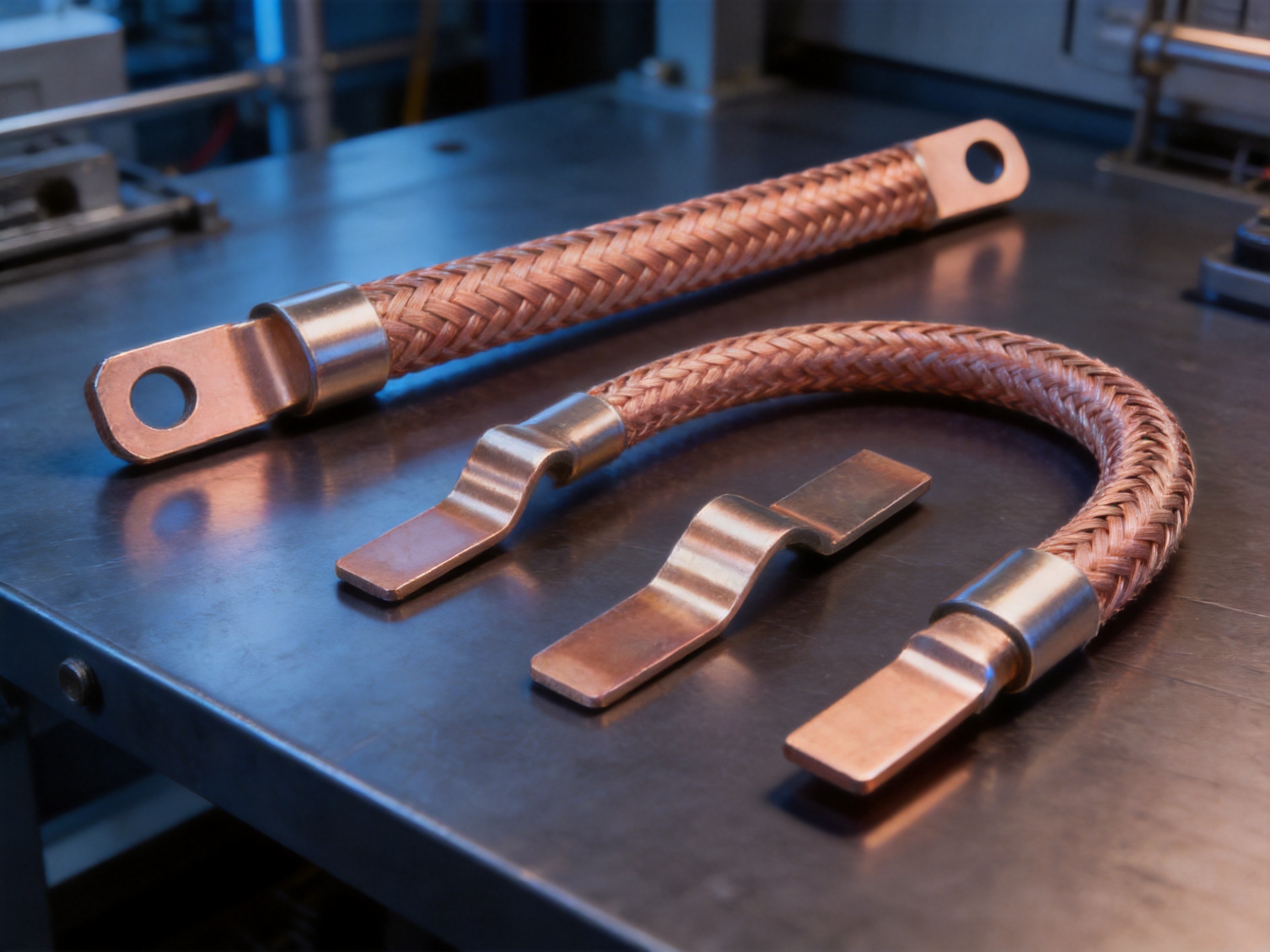
The PBCR Series Soft Braided Tape is a flexible copper connection manufactured from fine electrolytic copper wires with an individual wire diameter of approximately 0.15 mm. These fine wires are braided into a flat, flexible conductive tape and joined with integrated connector ends containing mounting holes. The result is a compact current-carrying component that can accommodate movement and vibration while maintaining a low-resistance electrical path.
Unlike a conventional rigid copper bar, the braided tape can bend, flex, and absorb mechanical displacement. Unlike a conventional cable with crimped lugs, it can provide a broad, low-profile connection surface and may not require a separate lug-crimping operation. This makes the product especially useful where electrical equipment is exposed to vibration, thermal cycling, assembly tolerances, or relative movement between connected components.
The integrated connector design is one of the most important features of the series. The terminal portions are manufactured as part of the connection assembly, with hole sizes and terminal dimensions selected according to the product configuration. Installers can therefore use bolts, screws, or other appropriate fastening hardware to secure the connector directly to the mating equipment.
The PBCR Series is described as a soft braided tape with a ready-to-use integrated connector. This design can simplify the transition between busbars, transformer terminals, grounding points, welding equipment, and other power connection locations. It is particularly suitable where the connection must remain electrically stable while allowing a degree of movement.
2. Why Flexible Copper Connections Matter
Rigid conductors are highly effective in fixed installations, but they can become vulnerable when connected equipment moves or expands at different rates. Transformers, switchgear, battery modules, welding equipment, and power conversion systems may experience vibration, electromagnetic forces, and temperature changes during operation. If these forces are transferred directly into a rigid connection, stress can accumulate at the terminal, bolt, busbar, or equipment interface.
A flexible braided connection acts as a mechanical transition zone. The individual fine copper wires move slightly relative to one another, allowing the connection to bend without concentrating all the stress at a single point. This can reduce mechanical loading on the connected equipment and help accommodate minor misalignment during installation.
Thermal expansion is another important consideration. Copper, aluminum, steel, insulation materials, and equipment housings do not all expand at the same rate. A flexible connector can absorb some of the resulting movement, reducing the risk that thermal cycling will loosen fasteners or fatigue a rigid conductor.
Vibration resistance is also important in industrial environments. Transformers, motors, inverters, welding machines, rail equipment, and battery systems may be exposed to continuous or intermittent vibration. A properly designed braided copper connection can reduce vibration transfer and help protect the connection from repeated bending stress.
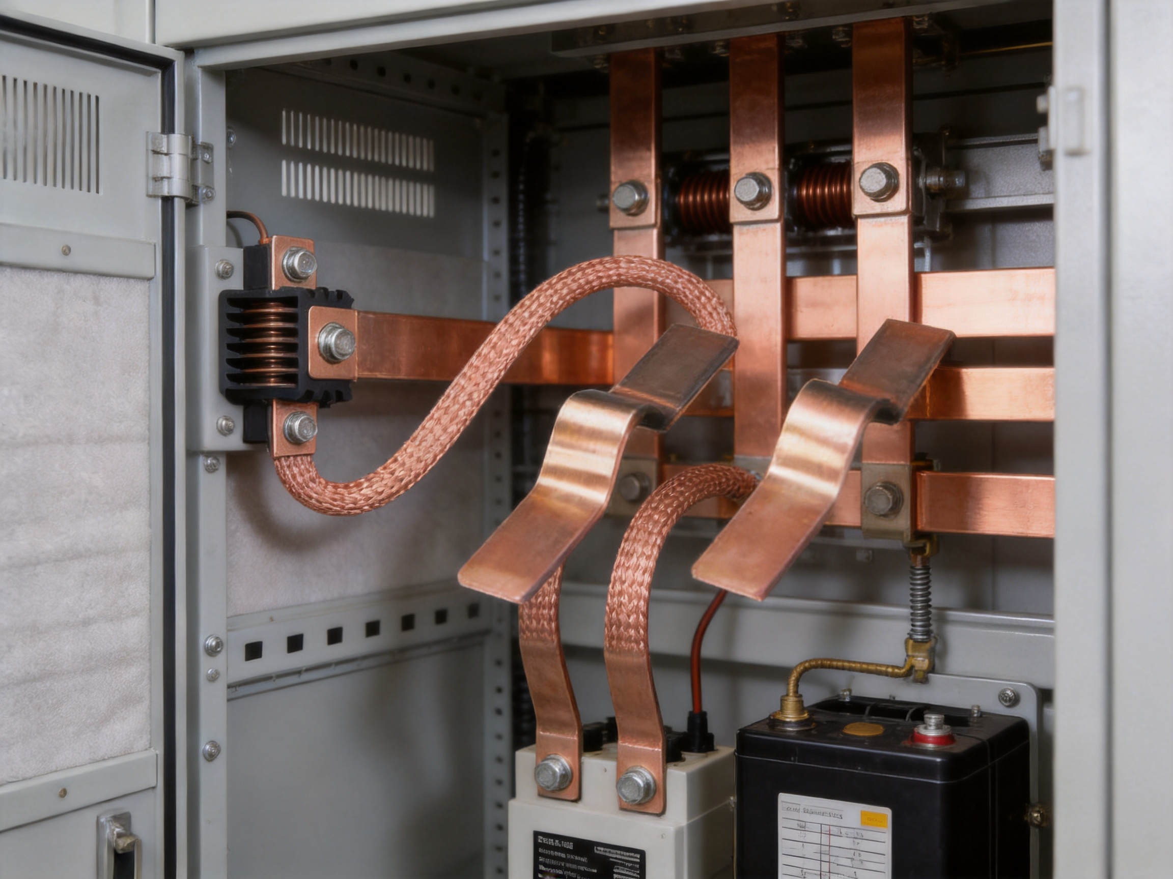
For these reasons, flexible copper links are frequently installed between rigid busbars and moving or vibrating equipment. They are also used as grounding straps, transformer slot connections, battery interconnects, and flexible links between adjacent electrical assemblies.
3. Key Product Advantages
3.1 High Electrical Conductivity
The PBCR Series uses electrolytic copper wire, a material widely selected for electrical conductors because of its strong conductivity, good thermal performance, and compatibility with many power connection systems. The use of fine copper wires creates a large number of conductive paths throughout the braid. This construction helps the tape carry substantial current while remaining flexible.
The available cross-sectional areas include 70 mm², 100 mm², 120 mm², 185 mm², and 240 mm². These sizes allow engineers to select a connector according to current demand, permissible temperature rise, available installation space, and mechanical requirements.
At a 30 K temperature rise, the listed current ratings range from 226 A for the 70 mm² version to 556 A for the 240 mm² version. At a 50 K temperature rise, the ratings range from 362 A to 890 A. These values provide a practical basis for preliminary selection, although the final allowable current must always be verified against the complete installation, including ambient temperature, enclosure conditions, ventilation, contact resistance, duty cycle, and applicable standards.
3.2 Exceptional Flexibility
Flexibility is the defining advantage of a braided tape connection. The approximately 0.15 mm copper wires are substantially finer than the conductors used in many conventional rigid or semi-rigid links. Their small diameter allows the braid to flex across its width and length, making it suitable for tight installation spaces and equipment interfaces that require movement.
The soft construction can simplify routing around obstacles and help installers align the connector with the equipment terminals. It may also reduce the need to force a rigid busbar into position. This is valuable in compact switchboards, transformer compartments, battery enclosures, and power conversion cabinets where access is limited.
High flexibility should not be confused with unlimited bending capability. The connector should be installed with an appropriate bend radius, supported where necessary, and protected from sharp edges or excessive torsion. Correct installation is essential to preserve the braid structure and prevent unnecessary fatigue.
3.3 Integrated Connector Holes
The integrated hole design provides a direct fastening interface. Instead of manufacturing a separate braided conductor and then adding a terminal lug through a secondary operation, the PBCR configuration incorporates the connection end into the product. This can reduce the number of components required in an assembly and support a more consistent installation process.
Integrated holes also help standardize the mounting position. The supplied configurations include hole-related dimensions such as 8.5 mm, 10.5 mm, and 12.5 mm, depending on the model. These dimensions can be matched to the selected bolt size and equipment interface after confirming the complete technical drawing.
A direct bolted interface can be particularly useful in high-current applications because it provides a broad contact area when correctly installed. The mating surfaces should be clean, flat, properly aligned, and tightened according to the fastener manufacturer’s recommendations. Contact pressure, surface treatment, and joint preparation have a direct influence on connection temperature and long-term reliability.
3.4 Reduced Assembly Operations
A conventional flexible connection may require cutting, stripping, crimping, pressing, tinning, or attaching separate terminals before installation. Each additional operation introduces opportunities for variation. Incorrect crimp pressure, incomplete insertion, contamination, uneven tinning, or unsuitable tooling can affect the final connection.
The PBCR Series is supplied as an integrated connection and is described as ready to use. In suitable applications, this can reduce the need for tinning or pressing joints. Fewer assembly steps may shorten production time, reduce tooling requirements, and improve consistency across repeated installations.
This advantage is especially relevant to original equipment manufacturers producing switchboards, transformers, battery packs, energy storage equipment, welding systems, or industrial control assemblies. A standardized flexible connector can make work instructions simpler and reduce dependence on operator-specific fabrication skills.
3.5 Lower Weight Than Some Rigid Alternatives
By replacing a heavier rigid copper component or a multi-part connection, a braided tape can reduce the weight of the local assembly. Lower weight can be valuable in mobile equipment, rail applications, battery systems, compact electrical cabinets, and installations where the supporting structure must be minimized.
Weight reduction also helps reduce the mechanical load transferred to terminals and mounting points. However, electrical performance and mechanical suitability must always remain the primary design criteria. Engineers should consider the selected cross section, current rating, length, terminal configuration, and environmental conditions rather than choosing solely on the basis of mass.
3.6 Vibration Reduction
The soft braided structure helps decouple connected equipment from some forms of vibration. Instead of behaving as a rigid lever between two terminals, the braid can move with the equipment and distribute mechanical displacement across many fine wires.
This property makes the PBCR Series suitable for transformer busbar slot connections, where equipment vibration and thermal movement may occur simultaneously. It can also be considered for power supply connections, grounding points, welding systems, and other assemblies that experience dynamic loads.
Vibration performance depends on installation geometry. The connector should not be pulled tight between terminals, twisted excessively, or forced to support the weight of another component. Where necessary, adjacent parts should be independently supported so that the braided connector performs its intended electrical and flexible-link function.
4. Product Range and Technical Selection
The PBCR Series provides several cross-sectional options and multiple lengths. The supplied models include 230 mm, 330 mm, and 430 mm connection lengths for many sizes. Length selection should account for the actual terminal spacing, required bend shape, installation movement, and clearance from nearby conductive or grounded components.
A connector that is too short may be placed under tension or forced into a sharp bend. A connector that is unnecessarily long may create unwanted loops, interfere with enclosure components, or increase electromagnetic proximity to adjacent conductors. The most suitable length is therefore the shortest option that permits correct routing without mechanical stress.
| Part Number | Model | Cross Section | Current at 30 K Rise | Current at 50 K Rise | Length | Hole or Terminal Dimensions |
|---|---|---|---|---|---|---|
| 23000402 | PBCR 70-230-8-10 | 70 mm² | 226 A | 362 A | 230 mm | 8.5 / 10.5 mm; A dimensions 9 / 11 mm |
| 23000403 | PBCR 70-330-8-10 | 70 mm² | 226 A | 362 A | 330 mm | 8.5 / 10.5 mm; A dimensions 9 / 11 mm |
| 23000404 | PBCR 70-430-8-10 | 70 mm² | 226 A | 362 A | 430 mm | 8.5 / 10.5 mm; A dimensions 9 / 11 mm |
| 23000405 | PBCR 100-230-8-10 | 100 mm² | 298 A | 477 A | 230 mm | 8.5 / 10.5 mm; A dimensions 9 / 11 mm |
| 23000406 | PBCR 100-330-8-10 | 100 mm² | 298 A | 477 A | 330 mm | 8.5 / 10.5 mm; A dimensions 9 / 11 mm |
| 23000407 | PBCR 100-430-8-10 | 100 mm² | 298 A | 477 A | 430 mm | 8.5 / 10.5 mm; A dimensions 9 / 11 mm |
| 23000408 | PBCR 120-230-10 | 120 mm² | 363 A | 581 A | 230 mm | 10.5 / 10.5 mm; A dimensions 11 / 11 mm |
| 23000409 | PBCR 120-330-10 | 120 mm² | 363 A | 581 A | 330 mm | 10.5 / 10.5 mm; A dimensions 11 / 11 mm |
| 23000410 | PBCR 120-430-10 | 120 mm² | 363 A | 581 A | 430 mm | 10.5 / 10.5 mm; A dimensions 11 / 11 mm |
| 23000411 | PBCR 185-330-10-12 | 185 mm² | 416 A | 666 A | 330 mm | 10.5 / 12.5 mm; A dimensions 12 / 14 mm |
| 23000412 | PBCR 185-430-10-12 | 185 mm² | 416 A | 666 A | 430 mm | 10.5 / 12.5 mm; A dimensions 12 / 14 mm |
| 23000413 | PBCR 240-330-10-12 | 240 mm² | 556 A | 890 A | 330 mm | 10.5 / 12.5 mm; A dimensions 12 / 14 mm |
| 23000414 | PBCR 240-430-10-12 | 240 mm² | 556 A | 890 A | 430 mm | 10.5 / 12.5 mm; A dimensions 12 / 14 mm |
The listed current values are associated with temperature-rise conditions rather than a universal operating current for every installation. The 30 K and 50 K designations indicate different permitted temperature-rise criteria under the referenced test or application conditions. Before specifying a connector, the system designer should confirm which temperature-rise limit applies to the equipment and enclosure.
The table summarizes the principal selection data provided for the PBCR Series. Additional dimensions, such as braid width, terminal length, spacing, packaging information, and product mass, should be confirmed from the latest approved drawing or quotation because the source data includes several dimensional and logistics fields that may require interpretation according to the manufacturer’s drawing convention.
5. Comparison with Conventional Connection Methods
5.1 Compared with Rigid Copper Busbars
Rigid copper busbars provide excellent conductivity and structural strength, making them appropriate for fixed routes and mechanically stable assemblies. However, they generally require accurate bending, drilling, alignment, and support. Any movement between the connected components can be transferred directly into the bar and its mounting points.
The PBCR Series provides greater flexibility and can compensate for minor positional differences. It is easier to route around equipment and can reduce the need for complex busbar bends. It may also reduce vibration transfer and thermal stress at the connection interface.
A rigid busbar may still be the better solution where the conductor must provide structural support, maintain a fixed geometry, or form part of an enclosed busbar system. The flexible braided tape is best viewed as a complementary connection technology rather than a universal replacement for every rigid conductor.
5.2 Compared with Flexible Cables and Crimped Lugs
Flexible cables are widely used for power connections and offer good routing capability. Nevertheless, cable assemblies normally require separate terminals, correct stripping, crimping, and inspection. The final performance depends on the conductor, lug, crimp profile, tooling, and installation procedure.
The PBCR Series integrates the braided conductor and connector ends into one product. This can reduce the number of interfaces and assembly stages. Its flat profile can also provide a different mechanical and thermal behavior from a round cable, especially where a broad connection surface is desirable.
Cables remain advantageous when long-distance routing, insulation, environmental sealing, or multi-axis movement is required. The uninsulated braided tape is particularly appropriate for short, high-current links where the connection can be installed inside a properly protected electrical enclosure.
5.3 Compared with Separate Copper Braids
Separate copper braids are flexible and can be effective for grounding and bonding. However, they may require additional terminals or fabricated ends before they can be installed as a power connection. A loose braid may also be more difficult to position consistently in a production environment.
The PBCR Series improves installation readiness by combining the braid with integrated connector holes. This can provide a more repeatable product geometry and reduce the risk of improvised terminal fabrication. It is therefore suitable for manufacturers seeking standardized parts for repeated equipment builds.
5.4 Compared with Tinned or Pressed Connections
Tinning and pressing can be useful processes, but they require controlled equipment and clear process parameters. Tinning may add material, increase stiffness near the joint, and introduce an additional thermal process. Pressing or crimping requires correct tooling, die selection, compression force, and inspection.
Because the PBCR Series is supplied as an integrated connector, it can reduce the requirement for these operations in suitable applications. This is a practical advantage for high-volume production and field service work, where minimizing specialized tooling can improve efficiency.
6. Manufacturing Strengths and Engineering Capability
Zhejiang Zhongyan New Energy Co., Ltd. specializes in conductive components and flexible electrical connection systems for power transmission, distribution, electric vehicles, rail transit, communications, and energy storage. Its product portfolio includes high-voltage electrical copper foil soft connections, special-shaped soft connections, battery soft connections, and other precision conductive components.
The company’s focus on soft connection technology supports the development of products that must balance electrical conductivity, mechanical flexibility, dimensional consistency, and long-term reliability. This specialization is important because a flexible connection is not simply a collection of copper wires. The braid pattern, terminal transition, joining method, hole geometry, thickness, and surface condition all influence performance.
6.1 Integrated Product Development
The company reports capabilities covering product design, research and development, manufacturing, testing, verification, and customized solution development. This integrated structure allows product geometry to be adjusted according to equipment layout, current requirements, fastening conditions, and production volume.
For OEM customers, this can be more valuable than purchasing a generic braid from a general electrical distributor. A connection may need a specific length, hole arrangement, terminal width, cross section, or installation orientation. Engineering support at the design stage can help ensure that the part is not only electrically adequate but also compatible with the complete assembly.
6.2 Modern Production and Quality Management
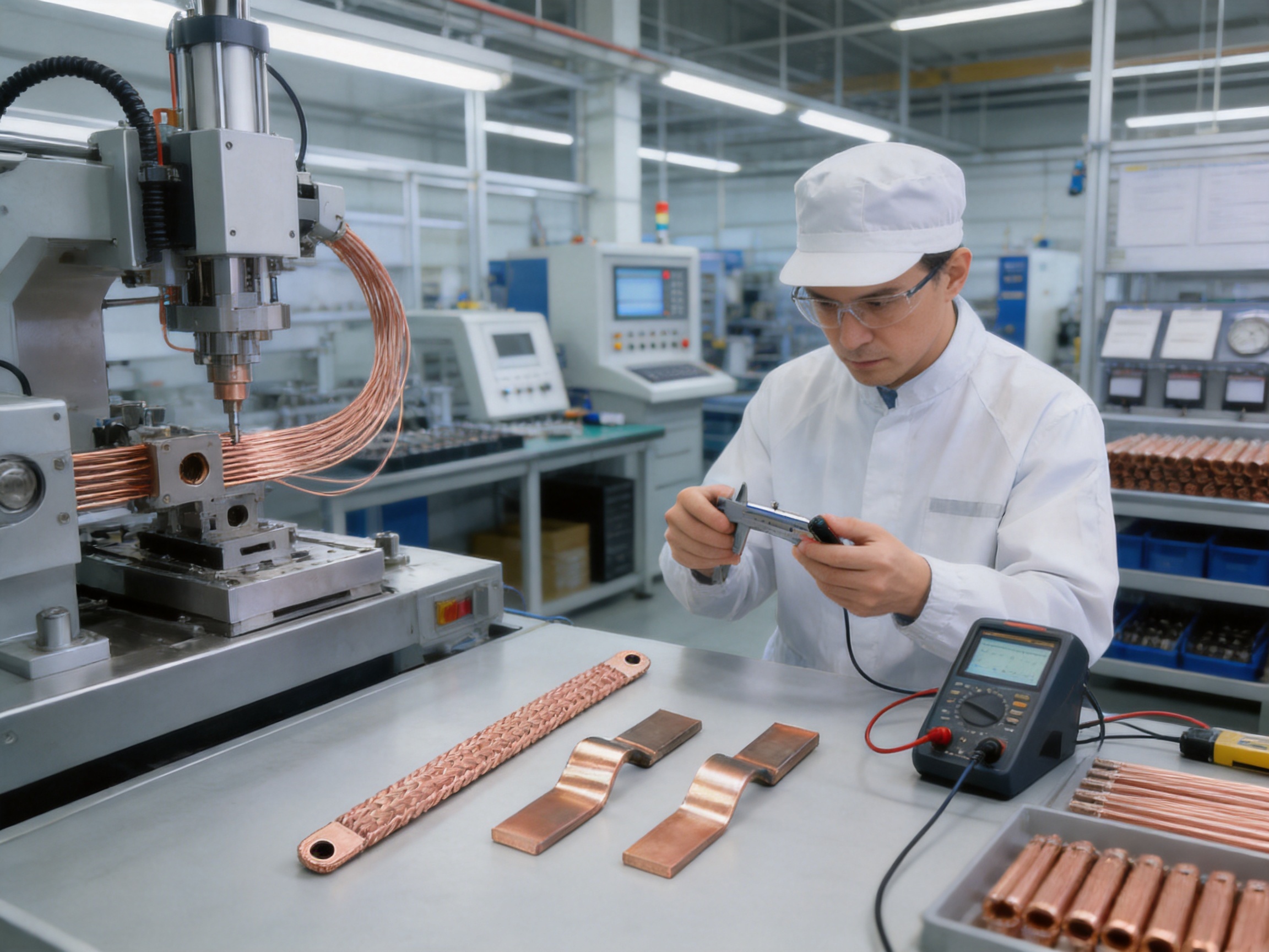
The company is equipped with professional production equipment and operates modern production and quality management systems. Consistent manufacturing is particularly important for braided copper products because small changes in braid density, terminal formation, joining quality, or dimensional accuracy can affect installation and electrical performance.
Quality control should cover incoming copper material, wire diameter, braid construction, terminal dimensions, hole position, surface condition, joint integrity, and final appearance. For high-current products, resistance and temperature-rise evaluation are also important. A controlled production process helps reduce variation between production batches and supports repeatable assembly in customer equipment.
6.3 Advanced Joining Technologies
The company identifies polymer diffusion welding and laser technology patents among its independently developed technologies. These technologies are associated with the production of battery soft connections and other precision conductive components. Advanced joining methods can help create connections with low internal resistance and high reliability when correctly designed and controlled.
For flexible copper products, the joining region must transfer current efficiently while tolerating the mechanical behavior of the braid. The connection should avoid sharp transitions that could concentrate stress or create excessive local heating. Precision joining technologies can contribute to a more controlled transition between the braided conductor and the integrated terminal area.
Laser-based processes may support accurate, localized manufacturing with limited heat influence on surrounding material. Diffusion-based processes can create strong material interfaces under carefully controlled conditions. The suitability of any joining method depends on the materials, geometry, process parameters, and required qualification tests.
6.4 Experience in New Energy Applications
Battery systems and energy storage equipment place demanding requirements on conductive components. Connections must often fit within compact spaces, accommodate thermal expansion, control resistance, and withstand vibration or repeated current cycling. Experience in battery soft connections can therefore strengthen the design approach used for other flexible high-current products.
The company is developing capabilities that connect battery cell technology with connection-system design. This integrated perspective can be useful for customers working on lithium battery packs, battery storage systems, electric vehicles, and high-power energy equipment. Instead of treating the connection as an isolated commodity, the company can evaluate it as part of the complete electrical and mechanical architecture.
7. Recommended Applications
7.1 Transformer Busbar Slot Connections
The PBCR Series is described as a preferred product for transformer busbar slot connection applications. Transformers can generate vibration during operation, and their internal and external components may experience temperature-related movement. A flexible braided connection can help reduce mechanical stress between the transformer terminal and the associated busbar or distribution assembly.
When used in a transformer, the connector should be positioned to avoid contact with sharp metal edges, hot surfaces beyond its rated conditions, moving components, and areas where insulation clearance may be inadequate. The installation should also consider magnetic effects, short-circuit forces, and the possibility of high fault current.
7.2 Power Supply Connections
Power supply equipment often requires compact links between a rigid distribution bar and a terminal, switch, fuse, rectifier, inverter, or converter. The PBCR Series can provide a flexible transition where a solid bar would be difficult to align or where equipment movement must be isolated from the main busbar.
Its flat form factor can be advantageous in cabinets with limited depth. The available length options allow designers to select a configuration that follows the intended route without excessive slack.
7.3 Grounding and Bonding
The product description identifies 100 mm² use for grounding and welding applications. A flexible copper braid can provide a low-impedance bonding path between metallic structures, moving equipment, and grounding points.
Grounding applications must be designed according to the required fault current, duration, protective device operation, touch-voltage limits, and applicable electrical codes. The current ratings in the product table are based on temperature-rise conditions and should not automatically be interpreted as short-circuit withstand ratings. Fault-current performance requires separate engineering verification.
7.4 Welding Equipment
Welding systems can require high-current connections that withstand vibration, movement, and repeated thermal cycling. A flexible braided connection can be used between power terminals or as part of a grounding arrangement when its cross section, length, temperature performance, and mechanical protection are appropriate.
Welding environments may expose components to heat, spatter, oils, and mechanical impact. The connector should be protected from direct welding arc exposure and installed in a way that prevents damage to the braid or terminals.
7.5 Battery and Energy Storage Systems
Battery systems use flexible conductive links to connect cells, modules, busbars, contactors, fuses, and power conversion equipment. While the PBCR Series is not automatically a substitute for every battery cell contact system, its flexible high-current architecture can be considered for suitable battery storage and power distribution interfaces.
Battery applications require careful evaluation of insulation, creepage and clearance, short-circuit protection, thermal management, vibration, service access, and the compatibility of the copper surface with adjacent materials. Where the connector is installed near exposed battery potential, suitable insulation covers, barriers, or enclosure protection should be specified.
7.6 Rail Transit and Industrial Equipment
Rail and industrial equipment may experience vibration, shock, movement, and restricted installation space. Flexible braided connections can help maintain electrical continuity while reducing stress on terminals. The product should be qualified against the environmental, fire-safety, vibration, and mechanical requirements applicable to the specific industry.
8. Installation Guidelines
8.1 Confirm the Electrical Rating
Select the cross section using the actual continuous current, overload profile, ambient temperature, enclosure ventilation, duty cycle, and allowable temperature rise. The published 30 K and 50 K current values are useful selection references, but system-level verification remains necessary.
Where multiple connectors are installed in parallel, current sharing should be evaluated. Parallel links should have comparable lengths, contact conditions, and routing so that current does not concentrate in one branch.
8.2 Check the Mechanical Interface
Before installation, verify the hole diameter, terminal width, spacing, and bolt compatibility. The mounting surfaces should be clean and free of burrs, paint flakes, oil, or other contamination that could increase contact resistance.
Do not enlarge the connector holes without approval because drilling or cutting can damage the integrated terminal structure and alter the current path. If the equipment interface does not match the selected model, a different standard configuration or a customized design should be considered.
8.3 Avoid Excessive Tension and Twisting
The connector should be installed with enough slack to permit natural movement. It should not be stretched tightly between terminals or used to pull two pieces of equipment into alignment. Excessive tension can reduce flexibility and transfer mechanical stress into the terminal joints.
Twisting the braid around its longitudinal axis should also be minimized. The product is intended to flex in a controlled manner, not to serve as a torsion spring. The bend should be gradual, and the braid should not be folded sharply against itself.
8.4 Use Correct Fastening Practice
Bolted joints should use suitable hardware, washers, and torque values. The fastener arrangement must produce adequate contact pressure without crushing or deforming the terminal. Torque should be applied with calibrated tools when required by the equipment specification.
After installation, the joint should be inspected for full contact, correct alignment, sufficient clearance, and signs of braid damage. In high-current equipment, thermal imaging or temperature-rise testing may be useful during commissioning and maintenance.
8.5 Provide Environmental Protection
The PBCR Series is an exposed conductive component unless installed inside an insulated or enclosed system. It should be protected against accidental contact, conductive debris, moisture, corrosive chemicals, and mechanical abrasion.
Where the product is installed in a battery pack, energy storage cabinet, or high-voltage enclosure, the system designer should determine whether insulating barriers or terminal covers are required. Insulation must not prevent heat dissipation beyond acceptable limits, and it must be compatible with the operating voltage and environmental conditions.
9. Quality, Testing, and Reliability Considerations
A high-quality braided connector should be evaluated as both an electrical conductor and a mechanical component. Electrical testing may include conductor resistance, contact resistance, current-carrying capacity, and temperature-rise testing. Mechanical evaluation may include flexibility, terminal pull strength, vibration, bend endurance, and dimensional inspection.
For demanding applications, environmental tests may include thermal cycling, humidity exposure, salt spray or corrosion evaluation, and insulation or dielectric verification where insulating components are included in the assembly. The appropriate test program depends on the industry, voltage, current, installation environment, and customer specification.
Low internal resistance is particularly important in high-current systems. Even a small increase in resistance can create significant heat at high current because power loss rises with the square of current. A properly manufactured braid and a correctly installed terminal joint work together to minimize this loss.
Consistency between batches is also critical. OEM customers need the same hole positions, length, cross section, and terminal geometry for every production lot. Stable manufacturing processes and inspection procedures help prevent assembly delays and reduce the need for field modification.
The company’s stated capabilities in material science, precision machining, testing, and verification support a product-development approach that can address these requirements. Customers should request the latest technical drawings, test reports, material declarations, and quality documentation for applications that require formal qualification.
10. Customization and OEM Support
Standard PBCR models cover many common combinations of cross section, length, and terminal dimensions. However, electrical equipment often has unique space constraints or connection layouts. Customization may be required for a special length, hole pattern, terminal shape, braid width, surface treatment, or assembly orientation.
An effective OEM development process begins with the customer’s complete application information. Important data includes rated current, peak current, voltage, temperature range, terminal material, mounting method, available space, movement amplitude, vibration level, installation environment, and expected service life.
Drawings should define all critical dimensions, tolerances, hole locations, contact surfaces, allowable bend areas, and inspection points. Prototype samples can then be evaluated in the customer’s equipment before final production approval.
Because Zhejiang Zhongyan New Energy focuses on conductive components and custom soft connections, it can support customers that need more than a standard catalog part. Its engineering and manufacturing capabilities are intended to help transform a connection requirement into a repeatable production component.
11. Why the PBCR Series Can Offer a Competitive Advantage
The main competitive advantage of the PBCR Series is its combination of flexibility, integrated connector construction, high-current capability, and manufacturing readiness. Many competing connection methods provide one or two of these characteristics, but the PBCR design brings them together in a single component.
Compared with a rigid copper bar, the PBCR Series offers easier routing and better tolerance for vibration and movement. Compared with a cable and separately crimped lugs, it can reduce assembly stages and provide a compact flat connection. Compared with a loose braid, it offers a defined terminal arrangement and ready-to-use mounting holes.
The broad range of cross sections and lengths also improves design flexibility. Engineers can select a 70 mm² connector for lower-current applications or move to 240 mm² for higher current demand. Multiple length options support different equipment layouts without requiring the customer to fabricate each connection individually.
The company’s specialization in new energy conductive components adds another advantage. Battery systems, power electronics, energy storage equipment, and electric vehicles require connections that are compact, reliable, and compatible with automated or standardized assembly. Experience in these areas can help inform the design of flexible links for both conventional industrial equipment and emerging energy applications.
Another important advantage is the potential to improve total installed cost rather than merely reducing the purchase price of an individual part. A ready-to-use connector can reduce labor, shorten assembly time, minimize tooling, simplify inventory, and decrease the likelihood of inconsistent field fabrication. These benefits can be significant in high-volume production.
12. Responsible Product Selection
The correct connector should be selected through a complete electrical, mechanical, thermal, and environmental review. Product ratings should not be separated from the conditions under which they were established. A connector operating in a ventilated cabinet may perform differently from the same connector installed in a sealed enclosure with several adjacent heat sources.
Engineers should also review fault-current requirements, electromagnetic forces, insulation coordination, corrosion exposure, maintenance access, and the consequences of a connection failure. Where the connector is part of a safety-critical or high-energy system, qualification testing should be completed before volume production.
The PBCR Series provides a strong starting point for applications that need a flexible, high-current copper connection. Its final suitability depends on correct sizing, proper mounting, adequate protection, and compliance with the relevant technical standards.
13. Frequently Asked Questions
13.1 What is the main purpose of the PBCR Series?
The PBCR Series is designed to provide a flexible, high-current copper connection between electrical components. It is suitable for power supply links, transformer busbar slot connections, grounding, welding, battery-related assemblies, and other applications where vibration or movement makes a rigid conductor unsuitable.
13.2 What material is used in the braided conductor?
The product description specifies electrolytic copper wire with an approximate individual wire diameter of 0.15 mm. The fine-wire construction creates a flexible conductive braid with a substantial copper cross section.
13.3 Does the product include connector holes?
Yes. The PBCR Series is described as an integrated connector with holes and is intended to be ready for installation. Hole and terminal dimensions vary by model and should be checked against the latest technical drawing before ordering.
13.4 What cross-sectional areas are available?
The supplied product range includes 70 mm², 100 mm², 120 mm², 185 mm², and 240 mm² versions. The appropriate size depends on the required current, temperature rise, installation environment, and mechanical design.
13.5 What are the listed current ratings?
The listed current ratings range from 226 A to 556 A at a 30 K temperature rise and from 362 A to 890 A at a 50 K temperature rise. These values vary according to cross section. They should be treated as reference ratings that require confirmation for the complete system.
13.6 Can the PBCR Series be used for grounding?
Yes. The product description identifies the 100 mm² version for grounding and welding applications. Grounding design must also account for fault current, fault duration, protective-device operation, environmental exposure, and applicable electrical regulations.
13.7 Can the connector replace a rigid copper busbar?
It can replace a rigid busbar in suitable flexible-link applications, particularly where vibration, thermal expansion, or alignment movement is present. It is not intended to replace every rigid busbar because rigid bars may be required for structural support, fixed distribution routes, or specific enclosure systems.
13.8 Does installation require tinning or crimping?
The integrated connector design is intended to reduce or eliminate separate tinning and pressing operations in suitable applications. The connector is fastened through its integrated holes. The final installation method should follow the approved equipment drawing and fastening instructions.
13.9 How should the braid be installed?
The braid should be installed without excessive tension, sharp bending, twisting, or abrasion. Terminals should be aligned with the mating surfaces, and bolts should be tightened using appropriate hardware and torque values. The connector should also be protected from accidental contact and environmental damage.
13.10 Is the product suitable for battery storage systems?
The flexible high-current architecture can be considered for suitable battery storage and power distribution interfaces. Battery applications require additional evaluation of insulation, voltage, creepage, clearance, short-circuit behavior, thermal management, and vibration. The selected design should be validated in the complete battery assembly.
13.11 What information is needed for a customized connector?
Useful information includes required cross section, continuous and peak current, operating voltage, length, hole pattern, terminal dimensions, mounting orientation, available space, temperature range, vibration level, mating materials, surface treatment, and required testing. Providing a complete application drawing generally improves the speed and accuracy of customization.
13.12 What makes the manufacturer suitable for OEM projects?
The manufacturer focuses on conductive components and flexible connection systems and reports capabilities in design, research and development, precision manufacturing, testing, verification, and customized solutions. Its experience includes power distribution, electric vehicles, rail transit, communications, and energy storage applications.
14. Conclusion
The PBCR Series Soft Braided Tape is a practical solution for high-current electrical connections that require both conductivity and mechanical flexibility. Its electrolytic copper braid, fine wire construction, integrated connector holes, and range of cross-sectional areas make it suitable for power supply connections, transformer busbar slot connections, grounding, welding, battery systems, and industrial equipment.
Its advantages over rigid busbars, loose copper braids, and separately fabricated cable assemblies include easier routing, improved tolerance for vibration and movement, reduced assembly operations, and a consistent ready-to-use terminal structure. The product can also support lower installed weight and more compact equipment designs.
Behind the product, Zhejiang Zhongyan New Energy Co., Ltd. provides expertise in flexible conductive components, battery soft connections, precision manufacturing, and advanced joining technologies. Its reported capabilities in polymer diffusion welding, laser processing, testing, and customized engineering support are aligned with the increasingly demanding requirements of electric vehicles, energy storage systems, power distribution equipment, and industrial electrical assemblies.
For the best result, users should select the correct cross section and length, verify the current rating under actual temperature conditions, confirm the terminal geometry, and follow proper installation and protection practices. When these factors are addressed, the PBCR Series can provide a reliable and efficient flexible connection for modern electrical and new energy systems.
References
1. Product technical information supplied for the PBCR Series Soft Braided Tape, including model numbers, cross-sectional areas, current ratings, dimensions, and application notes.
2. Copper Development Association, Copper for Electrical Conductors and Busbar Applications.
3. International Electrotechnical Commission, Electrical Installations and Temperature-Rise Considerations for Low-Voltage Equipment.
4. International Electrotechnical Commission, Requirements for Power Connections, Conductive Components, and Electrical Assemblies.
5. General engineering practice for bolted electrical joints, flexible copper connections, grounding conductors, and current-carrying capacity evaluation.
6. Manufacturer information concerning flexible conductive components, battery soft connections, polymer diffusion welding, laser processing, testing, and customized OEM manufacturing.
Product: PBCR Series Soft Braided Tape

Driven by the development of new energy and aiming for "zero carbon".
Copyright © Zhejiang Zhongyan New Energy Co., Ltd. All Rights Reserved.
