 English
 Español

PBCR Soft Braided Tape: Flexible High-Current Connections for Modern Power Systems
Reliable electrical connections must carry high current, tolerate vibration, accommodate thermal movement, and remain stable throughout the service life of the equipment. In many power distribution and energy conversion systems, a conventional rigid busbar cannot satisfy all of these requirements at the same time. Rigid conductors provide low electrical resistance and mechanical strength, but they can transfer vibration, amplify installation stress, and experience high mechanical loading when connected equipment expands or moves. A flexible copper connection addresses these limitations by combining the conductivity of electrolytic copper with the movement capability of a finely braided conductor.
The PBCR Series Soft Braided Tape is designed for this purpose. It is a ready-to-use flexible connector manufactured from electrolytic copper wires with an individual wire diameter of approximately 0.15 mm. Its integrated connector ends include mounting holes, eliminating the need for separate tinning, crimping, or pressing operations in many installation arrangements. This all-in-one construction reduces assembly steps while providing a dependable current path between busbars, transformers, switchgear, grounding points, welding equipment, and other high-current electrical devices.
Available cross-sectional areas include 70 mm², 100 mm², 120 mm², 185 mm², and 240 mm². Depending on the selected model and thermal conditions, the published current-carrying capability ranges from 226 A to 1,149 A. The product is particularly suitable for applications requiring repeated movement, vibration absorption, thermal expansion compensation, or a compact connection between closely positioned conductive components.
This article explains the structure, electrical performance, mechanical advantages, manufacturing considerations, selection criteria, installation practices, and application value of the PBCR Series Soft Braided Tape. It also compares flexible braided connections with conventional rigid links and highlights the engineering capabilities of the manufacturer behind the product.
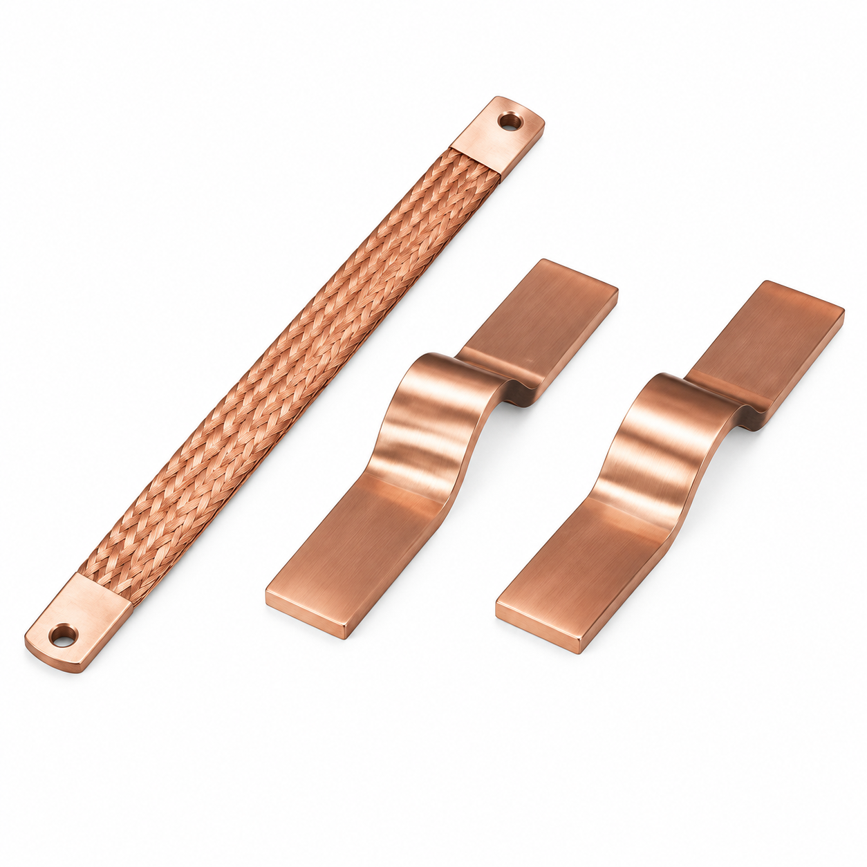
PBCR Series Soft Braided Tape
1. The Role of Flexible Connections in Electrical Equipment
Electrical equipment rarely operates in a completely static mechanical environment. Transformers generate electromagnetic forces and vibration. Switchgear experiences operating shocks and fault-current forces. Battery systems undergo thermal cycling during charging and discharging. Welding equipment is subject to frequent movement and high transient currents. Busbars may also be mounted between components manufactured from different materials, each having its own coefficient of thermal expansion.
When a rigid conductor is used in such a location, the conductor itself may be electrically effective but mechanically unsuitable. The connection can transmit vibration to terminals, create stress at mounting points, or concentrate force around bolts and interfaces. Repeated expansion and contraction can gradually loosen fasteners, fatigue a solid link, or damage the connected equipment. These problems may not be visible during initial commissioning, but they can affect contact resistance, temperature rise, and long-term reliability.
A flexible braided tape provides controlled compliance. Its woven structure can flex, bend, and absorb small movements without interrupting the electrical path. Instead of forcing the connected components to remain perfectly aligned, the connector accommodates their relative movement. The result is a connection that is both electrically conductive and mechanically forgiving.
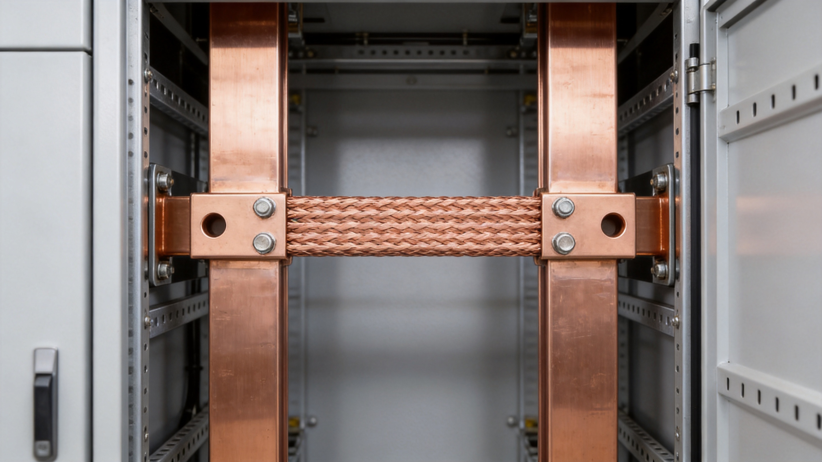
Flexibility is especially valuable where a busbar is connected to a transformer terminal, where equipment is installed on a vibrating frame, or where a conductor must pass through a limited installation space. It can also simplify maintenance because the connection may be repositioned or removed without bending a solid bar into a new shape.
1.1 Electrical continuity and mechanical compliance
The fundamental design objective is to achieve low-resistance current transmission without creating a rigid mechanical bridge. The PBCR Series uses many fine electrolytic copper wires arranged into a braided structure. Each wire contributes to the total conductive cross-section, while the interwoven geometry allows the assembly to flex in multiple directions.
This construction differs from a single thick copper strip. A solid strip is strong in its intended plane but may resist bending and transmit movement directly to its terminals. A braided tape distributes bending across numerous small strands. Individual wires move slightly relative to one another, reducing localized strain and allowing the connector to follow changes in position.
1.2 Thermal movement in busbar systems
Every current-carrying conductor produces heat. As current increases, the conductor temperature rises according to its electrical resistance, cooling conditions, ambient temperature, and installation arrangement. The conductor expands during heating and contracts during cooling. In a long rigid connection, this dimensional change can create substantial stress. In a flexible braided connector, part of the movement is absorbed through the braid.
The same principle applies to adjacent components. A copper busbar may be connected to a plated terminal, an aluminum component, a transformer bushing, or a battery assembly. If the materials expand at different rates, the flexible connector helps prevent that difference from being transferred directly into the terminal interface.
2. Product Construction and Operating Principle
The PBCR Series Soft Braided Tape consists of a flexible braided copper body and integrated terminal sections with prepared mounting holes. The connector is supplied as a finished component rather than as loose braid requiring a separate termination process. This ready-to-use design is one of the product’s most important practical advantages.
The conductive material is electrolytic copper wire with an approximate diameter of 0.15 mm. Fine wires provide a large number of individual bending elements. Compared with a small number of thick wires, this configuration generally offers greater flexibility and a smoother response to repeated movement. The braid also presents a broad conductive structure that can be connected to busbars and equipment terminals through bolted hardware.
The integrated connector ends are designed to provide a stable interface with mounting bolts. Depending on the product variant, hole dimensions include common values such as 8.5 mm, 10.5 mm, or 12.5 mm. The available product designs also include different connection widths and spacing dimensions. Selection should always be based on the actual terminal drawing, bolt size, clearance, and required current.
2.1 Ready-to-use integrated connectors
Many flexible braid products require an additional termination operation. The braid may need to be folded, compressed, soldered, tin-plated, crimped, or attached to separate copper lugs. Every additional operation introduces a possibility of variation in contact pressure, alignment, resistance, and production time.
The PBCR Series integrates the connector portion into the product. This can reduce the number of assembly stages and help standardize the connection. Installers do not need to prepare a separate end fitting for every braid length. The finished connector can be positioned directly between the mating terminals, subject to confirmation of the correct dimensions and hardware.
Eliminating unnecessary termination work can be particularly valuable in high-volume equipment production. It reduces dependence on manual workmanship, improves repeatability, and supports more consistent inspection. It also makes the connector easier to replace during servicing because the replacement part can match the original mounting arrangement.
2.2 Flexible braid geometry
The braided geometry combines current-carrying capacity with bending capability. The product is not intended to function as a loose cable that can be twisted indefinitely in every direction. Like all flexible electrical connectors, it should be installed without sharp bends, excessive torsion, or unsupported weight. Nevertheless, its braid structure provides significantly greater movement capability than a conventional solid copper link.
Proper geometry is important for maximizing service life. The connector should be installed so that its natural flexible direction is respected. Bolt holes should align without forcing the braid sideways. The conductor should not be stretched between terminals, and its bend radius should remain within the manufacturer’s recommended limits. A properly installed braid can then absorb vibration and thermal movement without creating unnecessary strain at the terminal ends.
3. Main Product Advantages
3.1 High conductivity
Electrolytic copper is selected for its high electrical conductivity and compatibility with a wide range of power connection applications. The braided copper structure creates a low-resistance path when correctly sized and properly fastened. The available cross-sectional areas allow the product to serve both medium-current grounding connections and high-current power links.
Published current-carrying values are provided under two temperature-rise conditions. For example, the 70 mm² models are listed at 226 A for a 30 K temperature rise and 362 A for a 50 K temperature rise. The 100 mm² models are listed at 298 A and 477 A under the same respective conditions. These figures demonstrate the importance of selecting the appropriate thermal criterion rather than relying only on nominal cross-section.
3.2 High flexibility
The fine 0.15 mm copper wires make the product highly flexible compared with solid busbar links and many coarse-strand conductors. This flexibility helps accommodate vibration, equipment movement, and installation tolerances. It is particularly useful for transformer busbar slot connections, where a rigid link may transfer mechanical energy into the transformer terminal or enclosure.
3.3 Vibration reduction
Vibration can cause fatigue, loosen fasteners, and damage rigid electrical interfaces. The PBCR braid acts as a compliant section between the connected components. Instead of transmitting every small movement directly through the terminal, the braid deforms elastically across its length.
Reduced vibration transfer can improve the durability of the complete assembly. It may also reduce noise and mechanical stress in equipment mounted on frames, cabinets, or mobile platforms. The result is not only a more flexible conductor but also a connection designed to protect the surrounding system.
3.4 Reduced installation weight
A flexible braided connector can replace a more elaborate assembly made from rigid bars, expansion sections, brackets, and separate terminal pieces. The integrated design reduces the number of components and can lower the overall weight of the connection. Lower weight is beneficial in switchgear, transformer assemblies, battery packs, and mobile electrical equipment where every additional component affects structural loading.
Weight reduction is also helpful during installation. A lightweight flexible connection is easier for technicians to position and align, particularly when working inside compact enclosures or at elevated locations.
3.5 Simplified assembly
The integrated holes and finished termination areas provide a connection that is ready for bolted installation. The absence of required tinning or pressing operations can shorten production time and reduce the need for specialized termination tools. A simplified assembly process supports consistent torque control, visual inspection, and replacement.
3.6 Broad application range
The PBCR Series can be used in transformer busbar slot connections, power distribution equipment, switchgear, grounding systems, welding equipment, industrial machinery, and other high-current applications. Its flexible construction makes it suitable wherever a conductor must combine current capacity with movement tolerance.
The product information identifies 100 mm² as a suitable size for grounding and welding-related applications. Other sizes extend the range from 70 mm² to 240 mm², allowing engineers to select a connector based on current, space, terminal geometry, and temperature-rise requirements.
4. Comparative Advantages Over Conventional Alternatives
4.1 Compared with rigid copper bars
Rigid copper bars are effective where the connection is short, stationary, and mechanically stable. They can be easy to inspect and may provide excellent short-circuit strength. However, they are not always the best solution where vibration or thermal movement is present.
Compared with a rigid bar, a braided connector offers greater flexibility, easier alignment, and lower mechanical stress at the terminals. It can compensate for small installation differences without forcing the busbar or equipment terminal into position. This is a major advantage in transformer and switchgear assemblies where the exact location of mating points may vary slightly after fabrication or transport.
A solid bar may also require additional expansion joints, flexible sections, or support hardware. The PBCR product combines the flexible function and terminal connection in one component, which can simplify the design and reduce the number of interfaces.
4.2 Compared with loose braided tape with separate lugs
Loose braid with separately attached lugs can provide flexibility, but its performance depends heavily on the termination process. Poorly compressed ends, inconsistent soldering, insufficient contact area, or improper alignment may increase resistance and localized heating.
The integrated PBCR construction is designed to provide a standardized finished connection. This supports more consistent production and reduces the risk associated with field-fabricated terminations. The installer still needs to confirm bolt torque, contact cleanliness, and correct fit, but the most critical manufacturing steps are completed before delivery.
4.3 Compared with flexible cables
Flexible cables are valuable for routed connections and applications requiring insulation or significant three-dimensional movement. However, a cable may require lugs, insulation stripping, bend-radius control, and additional termination hardware. It may also occupy more space than a flat braid in a busbar assembly.
A bare copper braided tape is often more suitable for short, high-current links where the connection must remain compact and where the surrounding assembly already provides the required insulation and guarding. The flat form can fit into busbar slots and narrow clearances while allowing movement along the connection path.
4.4 Compared with low-cost unqualified products
Product price alone does not determine connection cost. An inexpensive braid may have uncertain copper purity, inconsistent dimensions, weak terminal sections, poor hole alignment, or insufficient process control. These issues can lead to installation delays, increased contact resistance, and premature replacement.
A professionally engineered product offers value through controlled raw materials, repeatable geometry, documented current ratings, dimensional consistency, and stable manufacturing processes. The PBCR Series is intended to compete through total application reliability rather than through material cost alone.
5. Electrical Performance and Current Selection
Current selection must consider more than the nominal cross-sectional area. The final current capacity depends on ambient temperature, enclosure ventilation, conductor orientation, contact resistance, duty cycle, permissible temperature rise, neighboring conductors, and applicable standards. The PBCR data provides current values at 30 K and 50 K temperature-rise conditions to support preliminary selection.
| Cross-sectional area | Current carrier at Δ30 K | Current carrier at Δ50 K | Available connection lengths | Typical application focus |
|---|---|---|---|---|
| 70 mm² | 226 A | 362 A | 230 mm, 330 mm, 430 mm | Compact power links and grounding connections |
| 100 mm² | 298 A | 477 A | 230 mm, 330 mm, 430 mm | Grounding, welding, and medium-high current connections |
| 120 mm² | 363 A | 581 A | 230 mm, 330 mm, 430 mm | Flexible busbar and equipment connections |
| 185 mm² | 416 A | 666 A | 330 mm, 430 mm | High-current transformer and switchgear connections |
| 240 mm² | 556 A | 890 A | 330 mm, 430 mm | High-capacity power transmission links |
The published product information also identifies current-carrying values reaching up to approximately 1,149 A for a 240 mm² configuration under the stated 50 K condition. Engineers should use the exact product drawing and validated installation conditions when applying the highest current ratings.
5.1 Understanding temperature-rise ratings
A temperature-rise rating expresses how much hotter the conductor becomes than the surrounding reference environment under a specified current and test arrangement. A 30 K rise is more conservative than a 50 K rise. Equipment designers may choose the lower rise when the connector is installed near temperature-sensitive insulation, battery cells, electronic controls, or enclosed components.
The higher-temperature-rise value may be suitable in an appropriately designed installation with adequate clearances and thermal management. It should not automatically be treated as the continuous operating current for every application. The actual design must account for the complete thermal environment.
5.2 Contact resistance and joint quality
The braid itself is only one part of the current path. The bolted joints at both ends can significantly influence total resistance and temperature. Contact surfaces should be clean, flat, and free of contamination. Hardware should be compatible with the terminal materials, and the specified tightening torque should be followed.
Excessive torque may deform a terminal or damage a mounting surface. Insufficient torque may lead to contact movement, fretting, and increased resistance. The best electrical performance is achieved through a properly designed interface that combines adequate contact area, suitable hardware, correct torque, and protection against loosening where required.
6. Available Models and Dimensional Options
The PBCR range provides several cross-sections and lengths. Typical length options include 230 mm, 330 mm, and 430 mm for the 70 mm², 100 mm², and 120 mm² families. The 185 mm² and 240 mm² families are listed in 330 mm and 430 mm versions. Hole and terminal dimensions vary by cross-section to support the required current and mechanical interface.
| Part number | Model | Cross-section | Length | Current at Δ30 K | Current at Δ50 K | Hole configuration |
|---|---|---|---|---|---|---|
| 23000402 | PBCR 70-230-8-10 | 70 mm² | 230 mm | 226 A | 362 A | 8.5 mm / 10.5 mm |
| 23000403 | PBCR 70-330-8-10 | 70 mm² | 330 mm | 226 A | 362 A | 8.5 mm / 10.5 mm |
| 23000404 | PBCR 70-430-8-10 | 70 mm² | 430 mm | 226 A | 362 A | 8.5 mm / 10.5 mm |
| 23000405 | PBCR 100-230-8-10 | 100 mm² | 230 mm | 298 A | 477 A | 8.5 mm / 10.5 mm |
| 23000406 | PBCR 100-330-8-10 | 100 mm² | 330 mm | 298 A | 477 A | 8.5 mm / 10.5 mm |
| 23000407 | PBCR 100-430-8-10 | 100 mm² | 430 mm | 298 A | 477 A | 8.5 mm / 10.5 mm |
| 23000408 | PBCR 120-230-10 | 120 mm² | 230 mm | 363 A | 581 A | 10.5 mm |
| 23000409 | PBCR 120-330-10 | 120 mm² | 330 mm | 363 A | 581 A | 10.5 mm |
| 23000410 | PBCR 120-430-10 | 120 mm² | 430 mm | 363 A | 581 A | 10.5 mm |
| 23000411 | PBCR 185-330-10-12 | 185 mm² | 330 mm | 416 A | 666 A | 10.5 mm / 12.5 mm |
| 23000412 | PBCR 185-430-10-12 | 185 mm² | 430 mm | 416 A | 666 A | 10.5 mm / 12.5 mm |
| 23000413 | PBCR 240-330-10-12 | 240 mm² | 330 mm | 556 A | 890 A | 10.5 mm / 12.5 mm |
| 23000414 | PBCR 240-430-10-12 | 240 mm² | 430 mm | 556 A | 890 A | 10.5 mm / 12.5 mm |
These models are intended to cover common connection geometries, but standard catalog sizes cannot satisfy every enclosure, transformer, battery, or switchgear layout. Customized dimensions may be evaluated when the customer provides current requirements, terminal drawings, hole spacing, available length, installation angle, environmental conditions, and required quantity.
7. Manufacturing Process and Quality Strengths
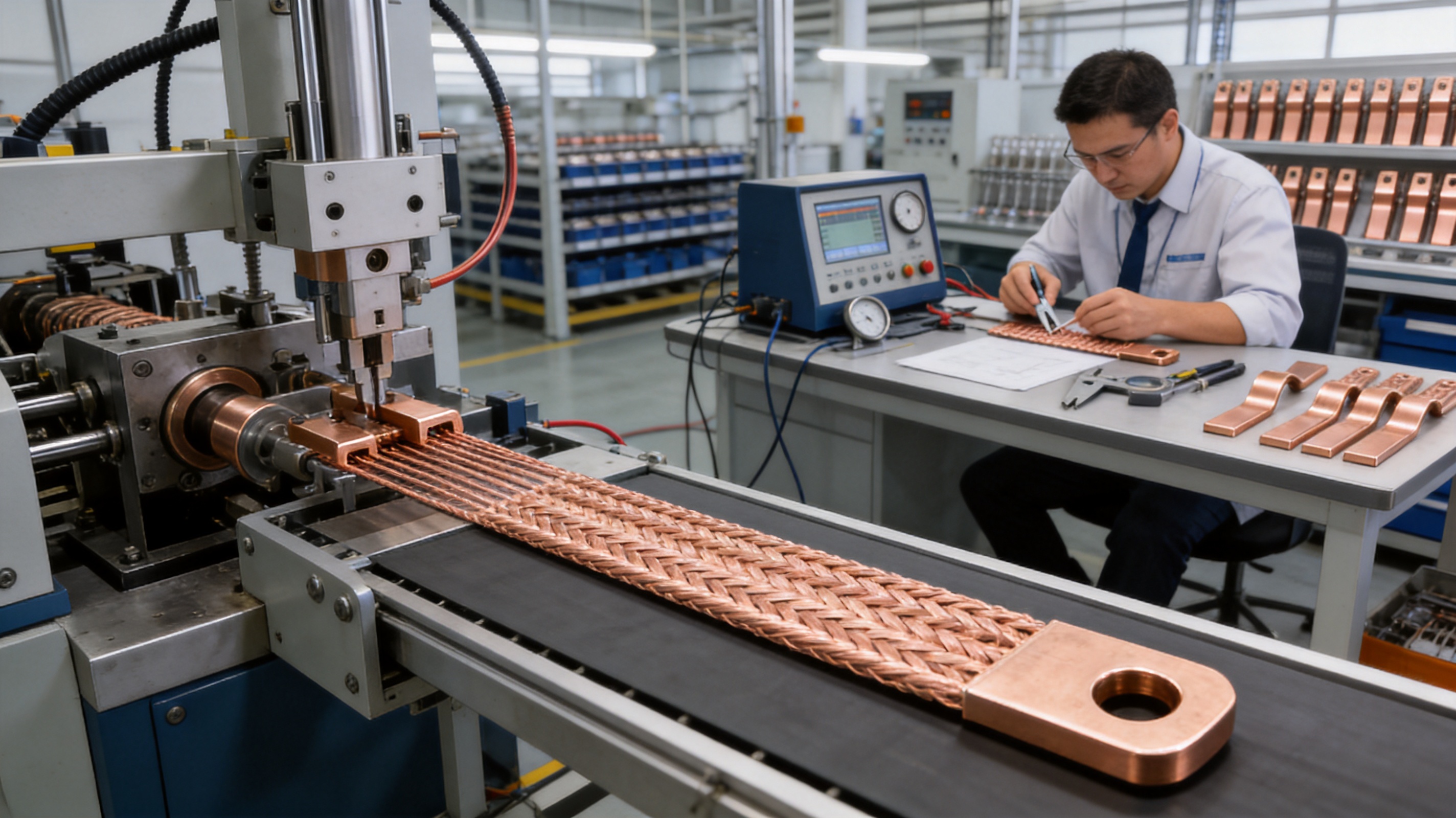
The performance of a flexible braided connector depends on the quality of its materials and on the consistency of its production process. A connector may look simple, but the electrical and mechanical behavior is influenced by wire diameter, copper quality, braid density, terminal formation, hole accuracy, surface condition, and final inspection.
7.1 Material control
The use of electrolytic copper wire with a controlled fine diameter supports predictable conductivity and flexibility. Material control begins with verification of incoming copper wire, including dimensional consistency, surface condition, and suitability for the intended forming process. Consistent wire diameter is important because variation can affect both the final cross-sectional area and the flexibility of the braid.
Material traceability also supports quality management. Raw material identification allows production teams to link finished products to defined material batches and manufacturing records. This is valuable for high-current applications where customers require stable performance over many production lots.
7.2 Precision braiding
The copper wires are arranged into a controlled braided structure. Braid density, width, thickness, and end formation must remain consistent to produce repeatable current capacity and mechanical flexibility. Excessively loose braiding may reduce dimensional stability, while excessively tight braiding may reduce movement capability.
Controlled production equipment helps maintain the geometry along the length of the product. Process technicians can monitor the braid appearance, width, thickness, and alignment. Consistent braiding also supports more reliable end forming and hole positioning.
7.3 Integrated end forming
The terminal sections are formed as part of the manufacturing process rather than being treated as an improvised accessory. The braid is consolidated and shaped to create a robust mounting area. Holes are then produced according to the selected model, with attention to diameter, center distance, edge distance, and surface condition.
End forming is a critical stage because it transfers current from the flexible braid into the fixed terminal. The transition must be mechanically stable and electrically continuous. Proper forming reduces the risk of loose wires, uneven pressure, or local hot spots at the connection ends.
7.4 Dimensional inspection
Finished products can be checked for overall length, width, hole diameter, hole spacing, terminal thickness, and visual quality. Inspection confirms that the connector will align with the equipment terminal without forced bending or drilling modifications at the installation site.
Dimensional consistency is particularly important for production customers. A connector that fits one assembly but requires adjustment in another can increase labor cost and compromise process repeatability. Stable dimensions support automated or semi-automated assembly lines as well as manual installation.
7.5 Electrical and mechanical verification
Product verification may include conductivity checks, resistance measurement, current-carrying tests, temperature-rise evaluation, and mechanical examination of the terminal areas. Depending on the application, customers may also request vibration testing, thermal cycling, pull testing, or repeated flexing evaluation.
The manufacturer’s engineering capability extends beyond basic fabrication. Its technical teams work across material science, precision machining, testing, and verification. This broader capability is important because flexible connectors are application-specific components rather than generic pieces of copper.
8. Advanced Engineering Capabilities
The manufacturer is a high-technology enterprise focused on new energy conductive components and precision electrical connections. Its product scope includes high-voltage copper foil soft connections, special-shaped flexible connections, battery soft connections, and other conductive components used in power distribution, electric vehicles, rail transit, communications, and energy storage.
The company was established in 2022 and has developed engineering capabilities covering product design, research and development, manufacturing, and solution support. Its technical teams combine practical experience in flexible connections with modern production equipment and quality management systems.
A key strength is the ability to develop products for complex electrical assemblies rather than offering only standard stock components. The same engineering foundation used for braided copper connectors can support battery connection systems, laminated busbars, battery terminal components, and customized conductive parts.
The company has also developed polymer diffusion welding and laser technology capabilities for advanced battery soft connections. These technologies are intended to create low internal resistance and high reliability in demanding new-energy applications. Although the PBCR Series is a braided copper product, the broader process knowledge contributes to a stronger understanding of current paths, joining methods, thermal behavior, and precision manufacturing.
Its customer base includes major enterprises in the new-energy and automotive sectors. Experience serving demanding customers helps strengthen process discipline, documentation, quality control, and responsiveness to customized requirements. Such experience is valuable when a flexible connector must be integrated into a larger battery, transformer, switchgear, or energy-storage platform.
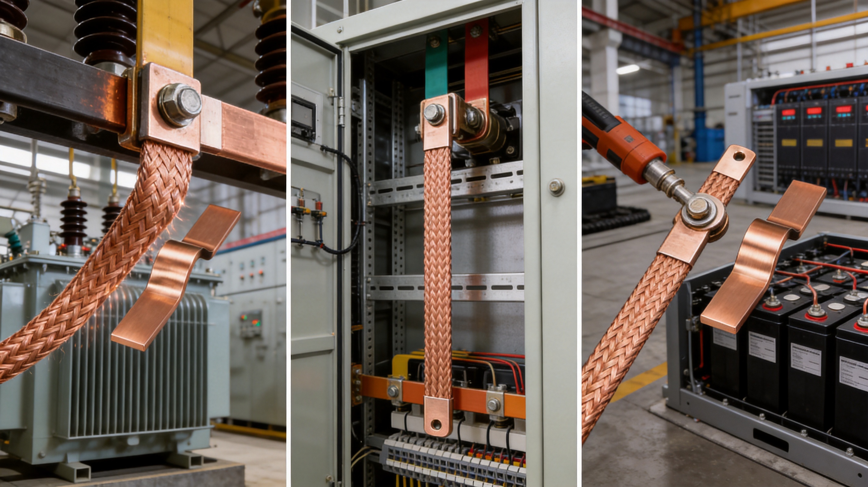
9. Applications Across Power and New-Energy Systems
9.1 Transformer busbar connections
Transformer terminals and busbar slots are a preferred application for the PBCR Series. Transformers can generate vibration and may experience movement caused by thermal expansion, electromagnetic forces, or transportation and installation tolerances. A soft braided tape between the transformer and busbar can reduce mechanical stress while maintaining current continuity.
The product is also useful where the connection space is compact and the busbar must approach the transformer terminal at a specific angle. Its flexibility allows easier alignment than a solid bar and can reduce the number of corrective bends required during installation.
9.2 Switchgear and power distribution equipment
Switchgear contains conductors, breakers, disconnectors, and terminals installed within a defined enclosure. Space is limited, and components may experience operating shock or fault-current forces. A flexible connector can accommodate small movements while reducing stress on the equipment terminals.
In power distribution cabinets, the braid may also be used as an expansion connection between sections of busbar. The correct clearances, insulation arrangements, and short-circuit support must be confirmed during equipment design.
9.3 Grounding systems
A flexible copper connection can be useful for grounding equipment doors, hinged structures, transformer frames, machine assemblies, and other components that move relative to the grounding point. The 100 mm² configuration is identified as suitable for grounding-related applications, subject to the grounding design and applicable electrical requirements.
Grounding connectors should be selected according to fault-current duty, duration, mechanical movement, corrosion environment, and required bonding impedance. The installation must provide a clean and secure metal-to-metal interface or an approved connection system.
9.4 Welding equipment
Welding equipment requires low-resistance current paths and may experience frequent movement, vibration, and high transient loads. A flexible copper braid can be used where a compact, robust connection is needed between conductive assemblies. The 100 mm² product size is identified for welding-related use, but final selection must consider the welding cycle, peak current, duty cycle, cooling, and environmental conditions.
9.5 Battery and energy-storage equipment
Energy-storage systems contain many electrical interfaces within limited space. The connections must handle current, thermal cycling, vibration, and manufacturing tolerances. While the PBCR Series is a general flexible copper connector, its design principles are relevant to battery racks, power conversion equipment, and high-current links between storage modules and busbars.
Battery applications may require insulation, controlled contact resistance, special plating, laser-welded interfaces, or highly customized geometry. The manufacturer’s wider portfolio includes battery soft connections, cell contact systems, and energy-storage connectors, allowing the braided product to be considered alongside more specialized solutions.
9.6 Rail transit and industrial machinery
Rail transit equipment and industrial machinery are exposed to vibration, shock, and repeated thermal changes. Flexible conductive links can protect fixed terminals and simplify the connection of moving or vibrating assemblies. The product should be integrated with suitable mechanical support and environmental protection based on the operating conditions.
10. Installation Recommendations
10.1 Confirm dimensions before installation
Before installation, verify the part number, cross-section, length, hole diameter, hole spacing, terminal width, and available clearance. A connector should fit naturally between the terminals. Do not force a short connector into position or stretch a long connector tightly between mounting points.
10.2 Avoid sharp bends and twisting
The braid is flexible, but it should not be folded sharply at the terminal edge or twisted around its longitudinal axis. A smooth bend distributes movement across the braided length and reduces localized fatigue. The terminal sections should remain flat against the mating surfaces.
10.3 Use suitable hardware
Select bolts, nuts, washers, and surface treatments that are compatible with the equipment terminal and the copper connector. In applications involving dissimilar metals, engineers should evaluate galvanic corrosion and use appropriate interface materials or plating. Hardware should provide sufficient contact pressure without damaging the terminal.
10.4 Apply correct tightening torque
Use the torque specified by the equipment designer, hardware supplier, or approved assembly procedure. Tightening should be uniform and controlled. If the connection is exposed to substantial vibration, a suitable locking method may be required, provided it does not interfere with the electrical contact surface.
10.5 Maintain electrical clearances
Although the copper braid may be compact, it remains a bare conductive component unless an insulating treatment is specified. Maintain the required phase-to-phase, phase-to-ground, and enclosure clearances. Prevent the braid from contacting sharp edges or moving components during operation.
10.6 Inspect after commissioning
After the equipment has operated under load, inspect the connection for unusual discoloration, loose hardware, deformation, or signs of overheating. Thermographic inspection can help identify abnormal temperature differences between similar connections. Periodic inspection intervals should be based on the application, current level, vibration, and maintenance program.
11. Customization and OEM Support
Standard models simplify procurement, but many projects require a customized connector. The manufacturer can evaluate customized copper braided straps and soft busbar connections according to electrical, mechanical, and environmental requirements.
Useful information for a customization request includes rated current, overload current, operating voltage, permissible temperature rise, conductor material, required length, hole dimensions, terminal shape, installation direction, minimum bend requirement, number of flexing cycles, ambient temperature, enclosure conditions, and required quantity.
For OEM customers, design support may include drawing review, sample production, dimensional confirmation, pilot batches, production tooling, and quality documentation. Early coordination helps ensure that the connector is not only electrically adequate but also compatible with the assembly sequence and available installation space.
Customization can include changes to cross-section, braid width, length, hole pattern, terminal configuration, plating, insulation, and special-shaped end geometry. The feasibility of each option depends on current demand, mechanical loading, production volume, and required validation.
12. Quality, Reliability, and Lifecycle Value
A flexible connector contributes to the reliability of the complete electrical system. A connection that remains cool, mechanically stable, and properly aligned can reduce unplanned maintenance. The value of the product therefore includes more than its initial purchase price.
Integrated ends reduce field operations. Controlled copper wire and braid geometry support consistent electrical performance. Accurate holes reduce installation adjustment. Flexible construction helps protect connected equipment from vibration and thermal movement. Together, these features can lower total lifecycle cost.
Reliability also depends on correct application. Even a high-quality connector can fail if it is undersized, installed under tension, exposed to unsupported mechanical loads, or used without appropriate environmental protection. Product selection and installation should therefore be treated as part of the equipment design process.
The manufacturer’s quality management approach combines professional equipment, experienced engineers, production control, and testing. Its focus on new-energy conductive components requires close attention to low resistance, repeatability, precision, and long-term stability. These strengths directly support the production of dependable braided copper connections.
13. Frequently Asked Questions
Q1: What is a soft braided tape?
A soft braided tape is a flexible electrical conductor made from many fine copper wires woven into a flat or tubular braid. It is used to connect busbars, terminals, equipment frames, transformers, and other conductive components where both current capacity and mechanical flexibility are required.
Q2: What makes the PBCR Series different from a simple copper braid?
The PBCR Series includes integrated connector ends with prepared mounting holes. It is supplied as a finished connection rather than as loose braid that must be terminated separately. This can reduce assembly operations and improve dimensional consistency.
Q3: What copper wire is used?
The product is manufactured from electrolytic copper wire with an approximate individual wire diameter of 0.15 mm. The fine wire structure supports high flexibility and effective current transmission.
Q4: What current can the product carry?
Published values range from 226 A to 556 A at a 30 K temperature rise and from 362 A to 890 A at a 50 K temperature rise for the listed standard sizes. The product range also identifies configurations reaching approximately 1,149 A under the stated conditions. Final current selection must consider the exact model, installation, ambient temperature, cooling, and applicable standards.
Q5: Is the product suitable for transformer connections?
Yes. Transformer busbar slot connection is identified as a preferred application. The flexible braid can reduce vibration transfer and accommodate thermal or installation movement between the transformer terminal and busbar.
Q6: Can it be used for grounding?
Yes. The 100 mm² configuration is identified for grounding applications, subject to the required fault-current duty, bonding design, environmental conditions, and local electrical requirements.
Q7: Can the braid replace a rigid copper busbar?
It can replace a rigid link in applications where flexibility and vibration absorption are important, but it should not be treated as a universal replacement. Engineers must compare current capacity, short-circuit forces, mechanical support, insulation, clearances, and installation requirements.
Q8: Does the product require soldering or crimping during installation?
The integrated connector design is intended to be installed by bolting and generally does not require field tinning, soldering, or crimping. The exact installation method depends on the equipment terminal and approved assembly procedure.
Q9: Are customized sizes available?
Customized copper braided straps and soft busbar connections can be evaluated. Customers should provide electrical ratings, dimensions, hole patterns, terminal drawings, environmental conditions, and production requirements.
Q10: What should be checked during installation?
Check the part number, length, hole alignment, contact-surface condition, bolt torque, bend shape, clearance, and mechanical support. The connector should not be stretched, sharply folded, twisted, or used to support external weight.
Q11: Can the product be used in battery systems?
It may be suitable for selected battery and energy-storage power connections, particularly where a flexible copper link is appropriate. Battery systems may also require insulation, special joining technologies, or customized low-resistance interfaces, so the exact application should be reviewed with the manufacturer.
Q12: Why is temperature rise important when selecting a model?
Temperature rise indicates how much hotter the connector becomes than the reference environment at a given current. A lower permissible temperature rise generally requires a more conservative current selection. The correct value depends on the enclosure, surrounding materials, duty cycle, and system thermal design.
14. Conclusion
The PBCR Series Soft Braided Tape is a practical solution for electrical systems that require high conductivity without sacrificing mechanical flexibility. Its electrolytic copper braid, fine 0.15 mm wires, integrated connector ends, and range of cross-sections provide a combination of electrical performance, vibration resistance, installation convenience, and design flexibility.
Compared with rigid copper links, the product can better accommodate vibration, thermal expansion, and alignment differences. Compared with loose braid requiring separate lugs, its finished integrated structure can reduce assembly complexity and improve repeatability. The available 70 mm² to 240 mm² sizes and multiple standard lengths support applications ranging from grounding and welding equipment to transformer busbars, switchgear, industrial machinery, and energy-storage systems.
The manufacturer strengthens the product offering through advanced conductive-component engineering, precision manufacturing, process control, testing capability, and experience in new-energy applications. Its wider technical portfolio includes high-voltage soft connections, battery connection components, laminated busbars, and other customized electrical products.
For the best result, the connector should be selected as part of the complete system design. Current rating, temperature rise, mounting geometry, vibration, short-circuit forces, insulation, environmental exposure, and maintenance requirements must all be evaluated. When correctly specified and installed, a soft braided copper connector can provide a compact, durable, and reliable bridge between fixed electrical components.
References
1. Manufacturer product specification for PBCR Series Soft Braided Tape.
2. Manufacturer dimensional and current-carrying data for flexible copper connectors.
3. General engineering principles for copper conductors, busbars, and flexible electrical connections.
4. Technical guidance on temperature rise, contact resistance, and bolted electrical joints.
5. Application practices for transformer busbars, switchgear, grounding systems, and high-current equipment.
6. Engineering literature concerning vibration control and thermal expansion compensation in electrical assemblies.
7. Quality-management principles for precision conductive components and new-energy electrical systems.
Product: PBCR Series Soft Braided Tape

Driven by the development of new energy and aiming for "zero carbon".
Copyright © Zhejiang Zhongyan New Energy Co., Ltd. All Rights Reserved.
