 English
 Español

PET Film Hot-Pressed PCB CCS Integrated Busbar for Advanced Battery Energy Storage
As battery systems become more compact, powerful, and intelligent, the electrical connection architecture inside a battery module has become a decisive factor in overall performance. A modern battery pack must collect voltage and temperature data, transmit signals reliably, distribute current safely, withstand mechanical and environmental stress, and fit within increasingly limited installation spaces. These requirements have encouraged manufacturers to replace conventional collections of wires, brackets, terminals, and separate sensing components with highly integrated Cells Contact System (CCS) solutions.
The PET Film Hot-Pressed PCB CCS Integrated Busbar is designed for this purpose. It combines a printed circuit board, battery voltage and temperature sensing functions, nickel collecting sheets, NTC thermistors, aluminum busbars, insulation materials, protective adhesive, and mechanical reinforcement into one coordinated assembly. The result is a thin, lightweight, reliable, and highly automated battery connection and monitoring system for energy-storage modules and other lithium battery applications.
This integrated busbar is particularly suitable for battery packs that require stable signal transmission, controlled current collection, fast thermal response, high insulation performance, and efficient production. Its design supports the development of safer and more compact battery modules while reducing assembly complexity compared with separately installed wiring harnesses and sensing components.
1. The Role of an Integrated CCS in Modern Battery Systems
A battery module is not simply a group of electrochemical cells connected in series or parallel. It is a coordinated electrical and thermal system that must be monitored continuously. Each cell or cell group can experience changes in voltage, temperature, internal resistance, and state of charge. If abnormal conditions are not detected quickly, the battery system may suffer from reduced service life, power loss, overheating, or safety incidents.
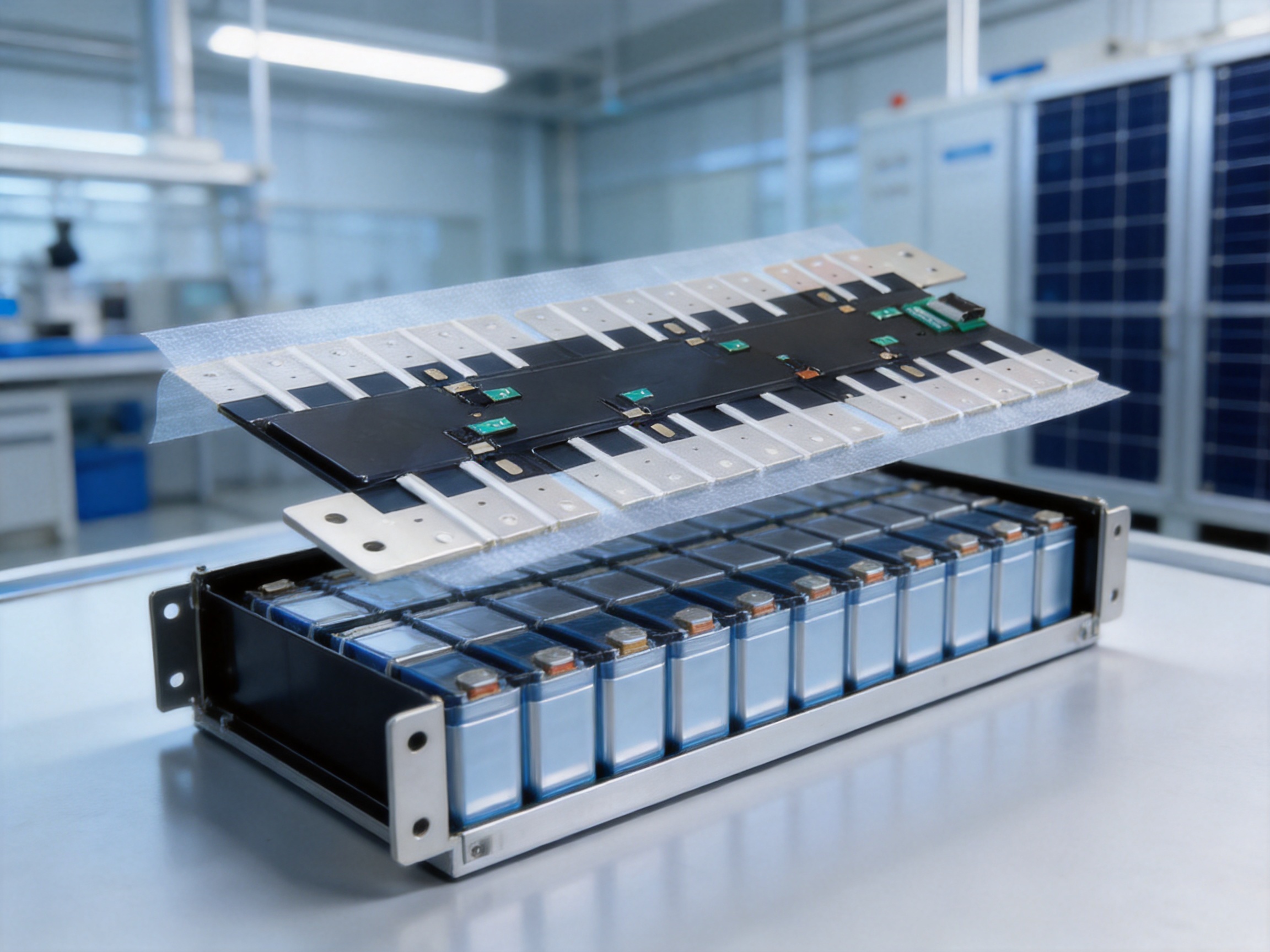
A Cells Contact System provides the physical and electrical interface between the cells and the battery management system. It collects voltage signals from individual cells or cell groups, monitors temperature through thermistors, and connects the cell terminals to the busbar structure. In an integrated design, these functions are combined into a compact assembly that can be installed on the cell module with fewer independent parts.
The PET Film Hot-Pressed PCB CCS Integrated Busbar uses a printed circuit board as the central signal-management platform. The PCB supports stable signal routing and incorporates current paths, fuses, connectors, and sensing interfaces. PET film and adhesive layers help create a thin insulation and protection structure, while aluminum busbars provide an efficient current-carrying connection between battery electrodes.
Compared with traditional wiring harnesses, an integrated CCS can offer improved dimensional consistency, simplified installation, lower assembly labor, better protection against incorrect wiring, and more controlled electrical performance. It also enables the manufacturer to design the connection system according to the exact dimensions, cell arrangement, terminal position, and monitoring requirements of the battery module.
2. Product Overview
The PET Film Hot-Pressed PCB CCS Integrated Busbar is a customized battery connection assembly intended for energy-storage modules and related battery integration applications. It is built around a PCB and a PET insulation structure that are hot-pressed and fused into a stable assembly. The design integrates conductive busbars, voltage collection points, temperature sensors, connectors, protective circuits, and mechanical reinforcement.
The product is engineered for applications in which space efficiency, signal accuracy, insulation reliability, and production automation are essential. Its flat structure allows the assembly to follow the surface of a battery module without creating unnecessary height. This is beneficial for battery packs with strict volumetric requirements, including stationary energy-storage cabinets, commercial energy-storage modules, industrial battery systems, and other high-density power applications.
The product can be developed according to customer requirements. Cell arrangement, busbar dimensions, signal routing, connector position, sensing-point quantity, temperature-sensor location, insulation structure, and mounting features can be adjusted to match the final battery design. This flexibility enables the CCS to function as an engineered module rather than a generic component.
The integrated structure also helps reduce the number of loose components that must be managed during battery-pack assembly. A conventional design may require independent busbars, wiring harnesses, plastic holders, temperature sensors, terminals, and protective covers. By combining many of these elements into one coordinated product, the integrated busbar can support a cleaner manufacturing process and more consistent quality control.
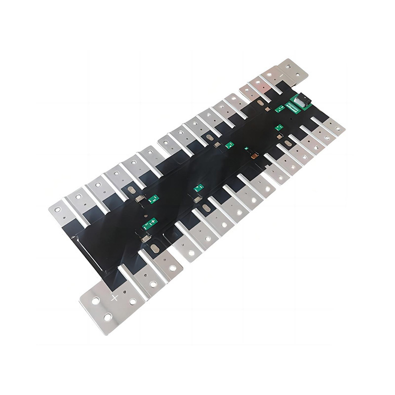
PET Film Hot-Pressed PCB CCS Integrated Busbar
3. Main Product Advantages
3.1 Stable Signal Transmission
The PCB provides a controlled platform for voltage and temperature signal routing. Compared with randomly arranged wires or manually installed harnesses, PCB-based routing offers a more repeatable circuit layout. The signal paths can be designed and verified in advance, reducing the risk of routing errors, poor connections, and inconsistent electrical behavior between production batches.
The product is designed to support long-term current carrying capacity of 1 ampere for the relevant PCB circuit. It also incorporates an overcurrent protection design capable of handling a specified 5-ampere current condition. The voltage-loop fuse can disconnect within 1.5 seconds when required by an abnormal condition. These features help protect the monitoring circuit and reduce the possibility that a fault in one section will damage other parts of the battery management system.
The loop resistance is specified at less than 1 ohm. Low resistance helps preserve signal quality and reduces unnecessary voltage loss within the sensing circuit. In a battery system containing many sensing points, consistent loop resistance is important because it supports reliable data interpretation by the battery management system.
3.2 Thin and Lightweight Construction
Battery manufacturers are under constant pressure to increase energy density while reducing unnecessary structural weight. The PET film and PCB-based architecture creates a flat, compact assembly that is significantly more space-efficient than a large bundle of separate wires and protective structures.
The use of AL1060-0 aluminum busbar material further contributes to weight reduction. Aluminum has a lower density than copper, allowing the product to achieve a lightweight current-conducting structure when the electrical and mechanical design are properly matched to the application. The aluminum busbar also provides fast heat dissipation and low impedance within the intended operating conditions.
Weight savings are especially valuable in mobile battery systems, but they are also relevant to stationary energy-storage products. A lighter internal assembly can make module handling easier, reduce installation effort, and simplify transportation and maintenance. The flat shape also helps battery designers use internal space more effectively.
3.3 High Insulation Performance
Battery modules may contain high voltages and large amounts of stored energy. Reliable insulation between conductive areas is therefore essential. The product uses PET film, a fire-retardant isolation board, protective adhesive, and carefully controlled PCB spacing to support electrical safety.
The insulation resistance is specified at more than 500 megohms when tested at 1000 volts DC. The product is also designed to meet a 2500-volt AC withstand-voltage requirement for 60 seconds, with leakage current below 1 milliampere. Certain finished-product configurations can withstand voltage levels up to 4200 volts DC. The final test level should be confirmed according to the customer’s approved drawing, application standard, and product configuration.
The insulation system is not limited to a single film layer. It is supported by isolation boards, adhesive protection, reinforced areas under connectors and nickel sheets, controlled creepage and clearance distances, and electrical testing during production. This multilayer approach helps protect the product against accidental contact, signal interference, and electrical breakdown.
3.4 Accurate Temperature Monitoring
Temperature is one of the most important operating parameters in a lithium battery module. Excessive temperature can accelerate degradation, reduce available power, and create safety risks. Uneven temperature distribution may also lead to different aging rates between cells.
The CCS incorporates surface-mount NTC thermistors for temperature acquisition. The standard temperature-acquisition resistance accuracy is specified as R25°C at 1 percent, with B-value accuracy also specified at 1 percent. These values can be customized according to the requirements of the battery-management strategy.
High sensitivity and fast response allow the temperature sensor to detect thermal changes quickly. The pure nickel sensing-end casing has a thin wall and fast heat dissipation characteristics, supporting efficient thermal coupling between the cell area and the sensing component. Accurate temperature data enables the battery management system to control charging and discharging more effectively.
3.5 Improved Appearance and Assembly Consistency
The product has a flat and aesthetically controlled appearance. This is not only a cosmetic benefit. A flat structure is easier to position, inspect, cover, and integrate with other battery-module components. It also reduces the possibility of loose wires becoming trapped, bent, or damaged during assembly.
Laser welding is used for selected connection and fixing operations. Laser welding can create strong and clean joints with a high degree of automation. It reduces dependence on manual soldering or mechanical fastening and supports consistent production from one unit to the next.
Because the connector locations, sensing points, and conductive routes are defined in the product design, the assembly process becomes more repeatable. This helps reduce installation errors and supports faster end-of-line inspection.
4. Materials and Functional Components
4.1 PET Insulation Film
PET is used as a key insulation and protection material in the integrated structure. The product uses single-sided adhesive PET that is hot-press fused to the PCB and related layers. Hot pressing creates a stable multilayer assembly and helps prevent movement between the insulation film and the circuit structure.
The PET film contributes to the product’s thin profile, electrical insulation, surface protection, and dimensional stability. Its use also supports clean production because the insulation can be formed according to the intended outline rather than applied as multiple manually cut pieces.
4.2 Printed Circuit Board
The PCB serves as the signal-processing and routing platform. It is designed to support long-term current carrying capacity, voltage collection, temperature-sensor connection, fuse protection, connector integration, and stable output to the battery management system.
Reinforcing plates are added beneath connectors and nickel sheets where additional mechanical support is required. This improves resistance to handling stress and helps maintain the reliability of soldered or welded areas. The PCB design can be adjusted to accommodate different cell counts, electrical layouts, and output interfaces.
4.3 Collecting Nickel Sheet
The collecting nickel sheet is made from pure N6-1/2H nickel with a nominal thickness of 0.3 millimeter. Nickel is widely used for battery connection and sensing interfaces because of its suitable electrical, welding, and corrosion-resistance characteristics.
The nickel collecting sheet provides a controlled contact between the cell terminal and the signal-collection circuit. Its thin-wall structure supports effective welding penetration and helps maintain a compact assembly. The sheet shape and position can be customized to match the cell terminal geometry and welding process.
4.4 NTC Thermistor
The surface-mount NTC thermistor provides temperature feedback to the battery management system. Its resistance changes according to temperature, allowing the control system to calculate the thermal condition of the monitored area.
Selection of the thermistor value, B-value, tolerance, and installation position can be adapted to the customer’s battery chemistry, thermal-management design, and software requirements. The standard accuracy targets support dependable temperature acquisition without requiring a bulky independent sensor harness.
4.5 Aluminum Busbar
The aluminum busbar uses AL1060-0 material. It is designed to provide a lightweight, low-impedance, and fast-heat-dissipating current path. Positive and negative electrode sections are pressed with 0.1-millimeter nickel material to support the required connection and welding interface.
The cleanliness requirement for the aluminum busbar is specified as RFU below 100. Controlled cleanliness is important because residue, particles, or surface contamination can affect welding quality, contact resistance, insulation performance, and long-term reliability.
4.6 Protective Adhesive and Isolation Board
Protective adhesives such as VS-8117B and UV0281 are used according to the approved product structure. These materials help secure components, cover exposed areas, and improve resistance to movement or environmental exposure.
The isolation board is designed to be fire-retardant and may use PCB, ABS, PA66, or other approved materials depending on the application. It provides mechanical protection and electrical separation around sensitive or high-voltage areas. Material selection can be adjusted according to flame-retardant, temperature, strength, and dimensional requirements.
5. Advanced Manufacturing Process
5.1 Customer Requirement Review
Manufacturing begins with a detailed review of the customer’s battery-module requirements. Engineers evaluate the cell format, cell spacing, terminal arrangement, series and parallel connection method, busbar current, voltage-monitoring points, temperature-monitoring points, available installation space, connector type, and required environmental performance.
The team also reviews the customer’s welding method, battery-management-system interface, mechanical fixing approach, and inspection standards. This early review is important because a CCS is closely connected to the complete battery architecture. A small change in cell spacing or terminal position can affect the busbar, PCB route, insulation outline, and connector location.
5.2 Integrated Design Development
After the requirements are confirmed, the engineering team develops the integrated design. The design process can include three-dimensional structure development, PCB layout, current-path analysis, temperature-sensor positioning, insulation-distance evaluation, busbar forming, connector selection, and fixture design.
Rather than treating the busbar, PCB, and insulation as separate products, the integrated approach evaluates them as one functional assembly. This can reduce interference between components and improve the efficiency of the final module installation.
Engineering verification focuses on loop resistance, current-carrying capability, voltage isolation, signal routing, fuse behavior, mechanical reinforcement, thermal response, and assembly compatibility. Prototype samples can then be produced for customer testing and design confirmation.
5.3 Material Preparation and Surface Control
Material preparation is controlled before production. Aluminum busbars, nickel sheets, PCB materials, PET film, thermistors, adhesives, connectors, and isolation boards are checked against the approved specification. Dimensions, surface condition, material identification, and relevant certificates are reviewed according to the quality plan.
Surface cleanliness is especially important for the aluminum and nickel connection areas. Contaminants can reduce weld penetration, increase contact resistance, and create inconsistent electrical results. Cleaning and handling procedures are therefore used to protect the connection surfaces before welding, pressing, or lamination.
5.4 Precision Forming and Positioning
Aluminum and nickel components are formed according to the approved drawing. The forming process establishes the final shape, spacing, and contact geometry required for the battery module. Precision fixtures help maintain the position of each component during processing.
PCB assemblies, thermistors, connectors, and reinforcing plates are positioned using controlled methods. The goal is to ensure that the final product has consistent dimensions and that every sensing point is located correctly relative to the corresponding cell.
5.5 Laser Welding
Laser welding is used for selected electrical and mechanical connections. It provides concentrated energy and enables accurate control of the welding area. The process can be automated to improve repeatability, reduce operator variation, and create clean connection points.
Laser-welded joints are evaluated for appearance, penetration, strength, and electrical resistance. The exact parameters depend on material type, thickness, joint geometry, and production speed. Controlled laser welding is particularly valuable for nickel collecting sheets and aluminum busbar connection areas where reliable low-resistance joints are essential.
5.6 Hot-Press Fusion
The PET film, PCB, and related protective layers are hot-press fused into the integrated assembly. Heat and pressure are controlled to achieve stable bonding without damaging the circuit, thermistors, connectors, or insulation material.
Hot pressing helps create a flat and uniform product. It also reduces the chance of air gaps, loose film edges, and component movement. Process parameters such as temperature, pressure, time, alignment, and cooling condition are monitored as part of production control.
5.7 Connector and Reinforcing-Plate Integration
Connectors are installed in the locations required by the battery management system and module structure. Reinforcing plates are added below connectors and nickel sheets where the design requires additional support. This improves resistance to assembly handling and vibration-related stress.
The final connector position must be checked against the battery-module fixture and the mating harness or control unit. Dimensional verification at this stage prevents problems during final battery-pack assembly.
5.8 Electrical and Safety Testing
Testing is conducted to confirm the basic electrical and insulation performance of the finished product. Typical checks include continuity, loop resistance, temperature-sensor resistance, fuse response, insulation resistance, withstand voltage, leakage current, and connector function.
The product is designed to support an insulation resistance above 500 megohms at 1000 volts DC. Withstand-voltage testing can include 2500 volts AC for 60 seconds with leakage current below 1 milliampere, while higher-voltage finished-product configurations may be verified up to 4200 volts DC. Test conditions are selected according to the approved specification and product configuration.
Electrical testing is supported by visual inspection and dimensional inspection. A product that passes only an electrical test but has an incorrect connector position or damaged insulation is not acceptable for battery-module integration. The manufacturing process therefore combines functional, dimensional, and appearance controls.
5.9 Traceability and Quality Management
Traceability supports stable production and efficient problem analysis. Material batches, process parameters, inspection results, and shipment records can be managed through the company’s quality system. This allows production teams to identify the source of a deviation and implement corrective action.
Consistent quality is especially important for CCS products because they are installed inside battery modules and may be difficult to replace after final assembly. Preventive control at the material, process, and inspection stages helps reduce field risk and supports long-term customer confidence.
6. Performance Characteristics
| Item | Specification or Characteristic | Application Benefit |
|---|---|---|
| Operating temperature | -40 to 125°C | Supports demanding battery-module environments |
| Temperature resistance accuracy | R25°C at 1%; B value at 1%, customizable | Improves thermal monitoring accuracy |
| PCB current capacity | Long-term current carrying capacity of 1 A | Supports stable sensing-circuit operation |
| Overcurrent protection | 5 A specified overcurrent condition | Protects the monitoring loop during abnormal events |
| Fuse disconnection | Voltage loop fuse can disconnect within 1.5 seconds | Limits the effect of electrical faults |
| Loop resistance | Less than 1 ohm | Reduces signal loss and supports consistent measurement |
| Insulation resistance | More than 500 megohms at 1000 VDC | Provides strong insulation reliability |
| AC withstand voltage | 2500 VAC for 60 seconds, leakage current below 1 mA | Verifies insulation under high-voltage stress |
| Finished-product voltage capability | Configurations up to 4200 VDC | Supports high-voltage battery architectures |
| Flame retardance | UL94 V-0 | Improves fire-safety performance of the insulation structure |
| Busbar material | AL1060-0 aluminum, with pressed nickel electrode sections | Provides low weight, low impedance, and heat dissipation |
| Temperature sensor | Surface-mount NTC thermistor | Enables compact and responsive temperature acquisition |
7. Competitive Advantages Over Conventional Solutions
7.1 Fewer Independent Components
A conventional battery connection system may use multiple cables, separate temperature probes, plastic holders, independent busbars, terminal blocks, and protective sleeves. Each additional component creates another opportunity for assembly error, poor contact, mechanical movement, or incorrect routing.
The integrated busbar consolidates many of these functions into a single engineered assembly. This simplifies material management and reduces the number of installation operations required by the battery manufacturer.
7.2 More Efficient Assembly
The flat, preconfigured design can be placed on the battery module and connected according to a defined assembly procedure. This is more efficient than routing and securing a large wiring harness by hand. Automated or semi-automated production can also be introduced more easily because the locations of the connectors, busbars, and sensing elements are controlled.
Higher assembly efficiency can reduce labor cost and improve production capacity. It also supports consistent takt time for battery-module manufacturing lines.
7.3 Better Space Utilization
Traditional cable harnesses require bending space, retaining clips, and clearance around wire bundles. The PET Film Hot-Pressed PCB CCS Integrated Busbar has a flat structure that follows the module layout more closely. This allows battery designers to use available internal space for cells, cooling structures, or additional protection rather than for cable management.
7.4 Reduced Wiring Risk
Incorrect polarity, disconnected terminals, damaged wires, and poor crimping are common risks in manually assembled harnesses. A designed PCB route and integrated connector system reduces the number of individual wiring operations. The product can be tested as a complete assembly before it is delivered to the battery-module line.
7.5 Controlled Electrical Performance
The product’s loop resistance, insulation resistance, fuse behavior, temperature resistance accuracy, and withstand-voltage performance can be checked against defined requirements. This gives the customer a more predictable electrical interface than a collection of separately sourced components with varying tolerances.
7.6 Lightweight Aluminum Current Path
The use of aluminum busbar material helps reduce weight while maintaining a suitable electrical path. The combination of aluminum busbar technology and pressed nickel electrode sections balances weight, welding compatibility, conductivity, and thermal performance.
7.7 Custom Engineering Support
Battery modules vary considerably in cell type, electrical arrangement, housing structure, sensing requirements, and interface definition. A standard off-the-shelf product may require compromises or additional adapters. A custom CCS can be designed around the customer’s module from the beginning, reducing the need for secondary modifications.

8. Application Areas
8.1 Stationary Energy Storage
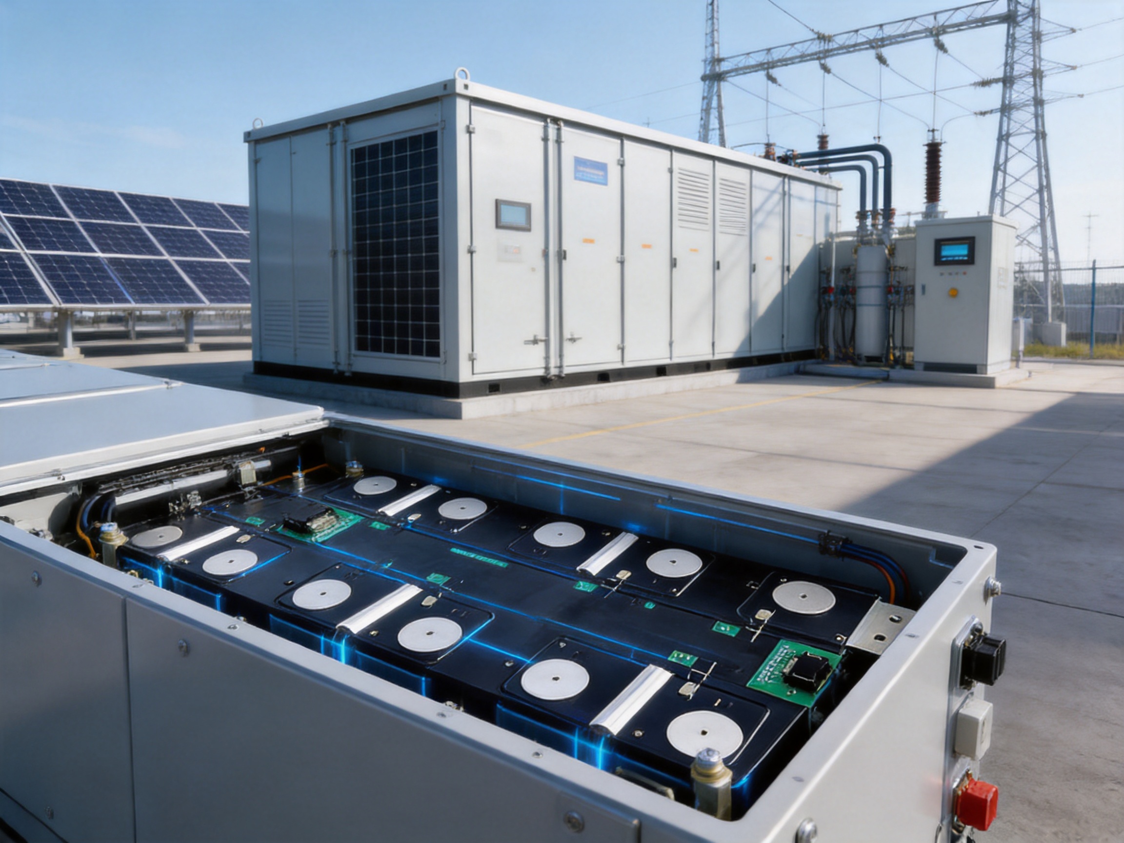
Energy-storage systems used for renewable-energy integration, peak-load management, backup power, and microgrids require reliable battery monitoring over long operating periods. The CCS can help organize cell interconnection and provide voltage and temperature data to the battery management system.
Its wide operating-temperature range, high insulation resistance, flame-retardant insulation structure, and integrated construction make it suitable for battery modules used in indoor and outdoor energy-storage equipment, subject to the complete system design and environmental validation.
8.2 Commercial and Industrial Battery Systems
Commercial and industrial batteries often use modular architectures that must be assembled efficiently and serviced consistently. The integrated busbar supports standardized module production while allowing customization for different capacity and voltage configurations.
The flat design can also assist with cabinet-level space management. When multiple battery modules are installed in a limited enclosure, reducing internal wiring volume can improve layout flexibility.
8.3 Lithium Battery Packs
Lithium battery packs for transportation, specialized equipment, and industrial machinery require accurate cell monitoring and controlled current collection. The CCS can be adapted to different cell formats and terminal arrangements, provided that the electrical, thermal, mechanical, and safety requirements are verified for the specific application.
8.4 Battery Testing and Development Platforms
Battery research, prototype development, and pilot production also benefit from integrated sensing and connection assemblies. A configurable CCS can shorten development time by providing a repeatable interface for cell monitoring and module-level testing.
9. Engineering Customization Options
Customization begins with the battery module drawing and technical requirement document. The design can be adjusted to support the number of cells, series-parallel topology, busbar current, voltage level, monitoring channels, temperature points, connector style, mounting method, and external dimensions required by the customer.
The PCB can be adapted for different output interfaces and fuse configurations. The aluminum busbar can be developed with different widths, thicknesses, lengths, bends, and terminal arrangements. Nickel sheets can be shaped to fit cylindrical, prismatic, or other approved battery-cell structures.
Insulation materials and isolation boards can be selected according to temperature, flame-retardant, mechanical, and dielectric requirements. PET film outlines can be modified to cover designated conductive areas while preserving access to connectors, weld points, and mounting locations.
NTC thermistors can be selected according to the required nominal resistance, B-value, tolerance, response time, and installation position. Sensor locations may be distributed across the module to identify temperature differences between cell groups.
Connector selection is also important. The connector must match the battery-management-system interface, electrical current, signal count, locking structure, installation direction, and service requirements. Connector position and cable exit direction can be modified to fit the complete pack architecture.
Before mass production, engineering samples should be evaluated for mechanical fit, welding quality, resistance, insulation, thermal response, vibration, environmental exposure, and compatibility with the customer’s assembly process. Design changes can then be incorporated into the controlled production drawing.
10. Manufacturing Strengths of the Supplier
Zhejiang Zhongyan New Energy Co., Ltd. specializes in new-energy conductive components and precision electrical connection products. Its product scope includes high-voltage electrical copper-foil soft connections, special-shaped soft connections, battery soft connections, busbar assemblies, and other components for power transmission, electric vehicles, rail transit, communications, and energy storage.
The company brings together experienced engineers and technical personnel with capabilities in product design, research and development, process engineering, manufacturing, and solution development. This combination is valuable for CCS projects because the product must be designed around both electrical performance and production feasibility.
The company’s experience with soft connections and precision components supports the development of low-resistance and high-reliability products. Independently developed polymer diffusion welding and laser technology patents contribute to the company’s ability to produce stable conductive connections for demanding battery applications.
Modern production and quality-management systems are used to improve product consistency. Material control, process monitoring, automated or semi-automated welding, hot-press fusion, electrical testing, and final inspection work together to provide a controlled manufacturing route.
The company was established in 2022 and has developed customer relationships with leading enterprises, including BYD, CATL, and Jaguar. Such experience reflects the importance of process discipline, engineering communication, and delivery consistency when supplying components for major energy and mobility projects.
The company is also developing a broader research and development system covering materials science, precision machining, testing, and verification. This supports continued improvement in conductive components and battery connection systems while helping customers address new requirements in energy storage and electrification.
11. Quality, Reliability, and Safety Considerations
Battery connection products must be evaluated as safety-related components. A defect in a busbar, sensing loop, insulation layer, or connector can affect the operation of the complete battery system. For this reason, quality control should begin with material selection and continue through design, production, inspection, packaging, and customer installation.
Electrical resistance testing confirms that the current and signal paths are continuous and within the specified range. Temperature-sensor testing confirms that the NTC components have the correct resistance characteristics. Fuse verification confirms the response of the protective circuit. Insulation-resistance and withstand-voltage tests verify the ability of the product to separate conductive areas safely.
Visual inspection is also important. Weld appearance, PET-film alignment, adhesive coverage, connector condition, busbar position, surface cleanliness, and signs of damage should be checked before shipment. Dimensional inspection ensures that the product can be installed without stress or interference.
Mechanical reliability should be considered during design validation. The product may experience vibration, thermal cycling, expansion and contraction, handling stress, and repeated connection or installation operations. Reinforcing plates, hot-pressed layers, laser-welded joints, and suitable protective materials help address these conditions.
Environmental performance depends on the complete battery-module design. The CCS should be evaluated together with the cell type, enclosure, cooling system, sealing structure, electrical protection, and installation method. Customer-specific validation is recommended before volume production.
12. Installation and Integration Recommendations
The battery-module assembly area should be clean and controlled before the CCS is installed. Dust, metal particles, oil, moisture, and other contaminants may affect insulation or welding quality. Operators should use the specified tools and handling methods to prevent bending, scratching, or deformation of the assembly.
The product should be aligned with the cell terminals and module locating features before any welding or fixing operation is performed. Excessive force should not be applied to the PCB, connector, thermistor, or PET film. The assembly should lie flat and should not be installed with unintended folds or sharp bends.
Welding parameters must follow the approved process specification. Inappropriate energy, pressure, alignment, or timing can create weak joints, excessive heat, incomplete penetration, or damage to nearby insulation. Weld quality should be checked during initial production and periodically during mass production.
After installation, the complete module should undergo continuity, insulation, voltage-acquisition, temperature-acquisition, and visual checks. The battery management system should be connected only after confirming that the CCS and module are free from short circuits or abnormal resistance.
13. Sustainability and Long-Term Value
Battery systems are a central part of the transition toward lower-carbon energy and transportation. Reliable connection components support this transition by improving battery safety, maintainability, and service life. A well-designed CCS can reduce assembly waste, simplify production, and improve material efficiency.
The lightweight aluminum busbar contributes to reduced material mass, while the integrated structure can reduce the quantity of separate harness components, holders, and protective parts. Automated welding and hot pressing may also reduce process variation and improve manufacturing efficiency.
Long-term value is created not only by the initial purchase price but also by installation speed, reduced error rates, stable performance, inspection efficiency, and compatibility with future battery-platform development. A custom CCS supplier that can participate in product design and process validation can help customers reduce total development and production risk.
14. Why Choose a Customized Integrated Busbar Solution?
A battery manufacturer may initially consider using standard busbars and separate sensing components because they appear simple to source. However, the total system often becomes more complex when the components must be installed, routed, secured, and tested individually. Assembly time increases, space becomes harder to control, and quality depends more heavily on operator technique.
A customized integrated busbar provides a defined connection architecture. The PCB route, sensing points, fuses, connector position, busbar geometry, and insulation layers are developed together. This enables the component to fit the battery module more accurately and makes the production process easier to standardize.
The PET Film Hot-Pressed PCB CCS Integrated Busbar is especially suitable when the customer needs a thin, lightweight, flat, and highly integrated assembly. Its combination of PCB signal routing, aluminum current collection, nickel sensing interfaces, NTC temperature monitoring, protective insulation, and automated joining creates a practical solution for advanced energy-storage modules.
With engineering support, precision manufacturing, and quality verification, the product can be adapted to both current battery platforms and future designs. Customers can work with the supplier from initial concept and prototype development through process validation and volume production.
15. Frequently Asked Questions
Q1: What is a PET Film Hot-Pressed PCB CCS Integrated Busbar?
It is an integrated battery connection and sensing assembly that combines a PCB, PET insulation film, aluminum busbars, nickel collecting sheets, NTC thermistors, connectors, protective circuits, reinforcing plates, and related insulation components. It is used to connect and monitor battery cells within an energy-storage module or battery pack.
Q2: What is the main advantage of using a PCB-based CCS?
A PCB-based CCS provides controlled signal routing, stable electrical performance, compact construction, and consistent production. It can reduce the number of individual wires and manual assembly operations required in comparison with a conventional wiring harness.
Q3: Is the product suitable for customized battery modules?
Yes. The busbar shape, PCB layout, cell count, connector position, sensing points, temperature-sensor specifications, insulation outline, and mounting structure can be developed according to the customer’s battery-module design and technical requirements.
Q4: What temperature range can the product support?
The specified operating temperature range is -40 to 125°C. Actual system suitability depends on the complete battery-module design, including the cell chemistry, enclosure, cooling system, environmental conditions, and customer validation requirements.
Q5: How accurate is the temperature acquisition function?
The standard temperature-acquisition resistance accuracy is R25°C at 1 percent, with B-value accuracy at 1 percent. These parameters can be customized when the customer requires a different thermistor specification or control strategy.
Q6: What type of temperature sensor is used?
The product uses surface-mount NTC thermistors. The NTC specification, nominal resistance, B-value, tolerance, and position can be selected according to the battery system’s monitoring requirements.
Q7: Why is aluminum used for the busbar?
AL1060-0 aluminum provides a lightweight current path with low impedance and fast heat dissipation. It helps reduce the mass of the battery connection structure while supporting the required electrical and thermal performance. Nickel-pressed electrode sections are used where appropriate to support the required connection and welding interface.
Q8: What insulation performance is available?
The product is specified with insulation resistance above 500 megohms at 1000 volts DC. It is designed to meet 2500 volts AC for 60 seconds with leakage current below 1 milliampere. Certain finished-product configurations can be verified up to 4200 volts DC. The exact requirement should be confirmed for each product design.
Q9: Does the product include overcurrent protection?
Yes. The PCB design supports an overcurrent protection condition of 5 amperes, and the voltage-loop fuse can disconnect within 1.5 seconds under the specified fault condition. Final protection behavior depends on the approved circuit and product configuration.
Q10: Can the CCS be used with automated battery-module production?
Yes. The flat, preconfigured structure, controlled connector position, laser-welded joints, and hot-press-fused insulation layers are suitable for automated or semi-automated production processes. The specific automation method should be developed together with the customer’s assembly line.
Q11: What information is required to begin a custom project?
Useful information includes the cell type and dimensions, cell arrangement, terminal drawings, series-parallel configuration, required current, voltage range, sensing-channel quantity, temperature-monitoring locations, connector requirements, installation space, welding method, insulation standard, operating environment, and expected annual volume.
Q12: What industries can use this integrated busbar?
Potential applications include stationary energy storage, commercial and industrial battery systems, renewable-energy storage, lithium battery packs, electric mobility, specialized equipment, communications backup power, and battery research or development platforms.
Q13: What makes the product different from a conventional wiring harness?
The integrated busbar combines current collection, signal routing, temperature sensing, protective circuitry, insulation, and mechanical support in one structured assembly. This can reduce wiring complexity, improve dimensional consistency, save installation space, and support more efficient inspection and production.
Q14: How is product quality verified?
Quality verification can include material inspection, dimensional inspection, visual inspection, continuity testing, loop-resistance testing, thermistor-resistance testing, fuse-function testing, insulation-resistance testing, withstand-voltage testing, leakage-current testing, and connector or assembly verification.
Q15: Who manufactures this product?
The product is manufactured and supplied by Zhejiang Zhongyan New Energy Co., Ltd., a Chinese high-tech enterprise specializing in new-energy conductive components, precision battery connections, busbar assemblies, and related electrical connection solutions.
16. Conclusion
The PET Film Hot-Pressed PCB CCS Integrated Busbar is a practical response to the growing demand for compact, reliable, and intelligent battery-module connection systems. By integrating a PCB, PET insulation structure, aluminum busbars, nickel collecting sheets, NTC thermistors, protection circuits, connectors, and reinforcing components, it provides more than a simple conductive path. It becomes an engineered interface between the battery cells and the battery management system.
Its principal advantages include stable signal transmission, low loop resistance, lightweight aluminum construction, high insulation resistance, high-voltage withstand capability, accurate temperature acquisition, fast thermal response, flat appearance, and support for automated production. The product also offers extensive customization for different cell layouts, module structures, connector interfaces, and monitoring requirements.
The supplier’s experience in precision new-energy components, soft electrical connections, laser welding, polymer diffusion welding, PCB integration, and quality-controlled manufacturing strengthens its ability to support complex battery projects. From initial design and sample development to validation and volume production, the company can provide a complete solution based on customer requirements.
For battery manufacturers seeking to improve assembly efficiency, reduce internal wiring complexity, optimize space, and achieve dependable cell monitoring, this integrated CCS busbar offers a strong foundation for next-generation energy-storage products.
References
1. IEC 60664-1, Insulation Coordination for Equipment Within Low-Voltage Systems.
2. UL 94, Tests for Flammability of Plastic Materials for Parts in Devices and Appliances.
3. IEC 62619, Safety Requirements for Secondary Lithium Cells and Batteries for Industrial Applications.
4. ISO 9001, Quality Management Systems—Requirements.
5. IPC-2221, Generic Standard on Printed Board Design.
6. Battery Management System Design and Application Engineering Guidelines.
7. Lithium-Ion Battery Pack Electrical Safety and Reliability Testing Practices.
8. Aluminum Alloy and Nickel Material Selection Principles for Battery Interconnection Components.
Product: PET Film Hot-Pressed PCB CCS Integrated Busbar

Driven by the development of new energy and aiming for "zero carbon".
Copyright © Zhejiang Zhongyan New Energy Co., Ltd. All Rights Reserved.
