 English
 Español

High-Current Flexible Busbar Connectors for EV Batteries and New Energy Systems
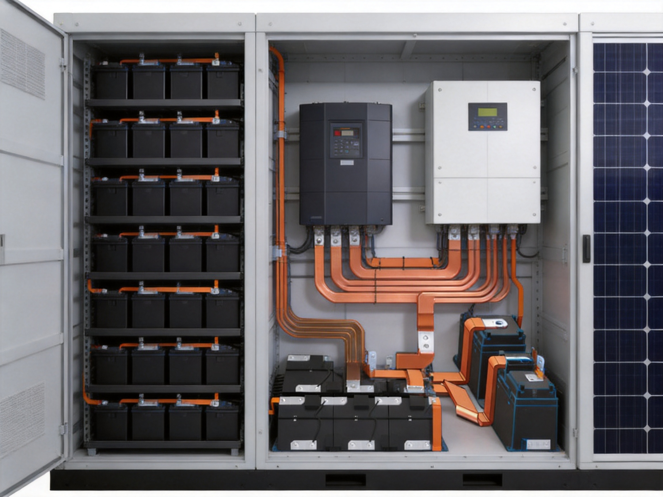
As electric vehicles, battery energy storage systems, renewable-energy installations, and modern power grids continue to expand, electrical connection components are becoming increasingly important. A battery system may contain advanced cells, sophisticated battery-management electronics, thermal controls, and high-performance inverters, but its overall reliability still depends on the quality of the conductive paths linking these components together. High-current flexible busbar connectors provide a practical solution for transmitting electrical power while accommodating vibration, thermal expansion, limited installation space, and repeated mechanical movement.
Unlike conventional rigid conductors, flexible busbar connectors combine high electrical conductivity with controlled flexibility. They can be bent, routed, and positioned inside compact battery packs and power equipment without the complex cable management often required by round cables. Their laminated copper construction also creates a low-profile current path with a large conductive cross-section, helping reduce electrical resistance, heat generation, and installation complexity.
Designed for electric vehicle battery packs, energy storage systems, new energy power grids, inverters, and power-distribution equipment, these flexible busbar connectors are available in a broad range of sizes and configurations. Product options include high-purity T2 copper or tinned copper conductors, welded or crimped terminals, customizable insulation, tin-plated surfaces, and a wide selection of dimensions, colors, and connection layouts.
The product range supports section areas from 10 mm² to 1,200 mm², current ratings from 50 A to 2,500 A, operating temperatures from -40°C to 125°C, and insulation withstand voltages from 600 V to 1,000 V, depending on the selected design. These capabilities make flexible busbar connectors suitable for both compact low-voltage battery assemblies and demanding high-current energy systems.
Content
- Understanding High-Current Flexible Busbar Connectors
- Why Flexible Busbars Are Important in New Energy Applications
- Core Product Advantages
- Applications in Electric Vehicle Battery Packs
- Applications in Energy Storage Systems
- Applications in New Energy Power Grids and Inverters
- Material Selection and Technical Configuration
- Manufacturing Process and Engineering Strengths
- Advantages Compared with Conventional Connection Solutions
- Customization Capabilities
- Technical Reference Table
- Quality, Reliability, and Compliance
- Company Manufacturing and Development Strengths
- How to Select the Correct Flexible Busbar
- Installation and Service Recommendations
- Sustainability and Lifecycle Considerations
- Frequently Asked Questions
- What is a high-current flexible busbar connector?
- Why use a flexible busbar instead of a rigid copper bar?
- Why use a flexible busbar instead of a cable?
- What copper materials are available?
- Can the busbar be customized for a specific battery pack?
- What current can these connectors carry?
- Are halogen-free insulation materials available?
- What terminal connection methods are available?
- Can flexible busbars be used in high-voltage battery systems?
- What operating temperature range is supported?
- How does tin plating improve the product?
- What industries use these flexible busbar connectors?
- How should the busbar be tested before mass production?
- What information should be included in an inquiry?
- What makes a specialized manufacturer different from a general metal fabricator?
- Conclusion
- References
- Product: High Current Flexible Busbar Connectors for EV Battery & New Energy Grid
Understanding High-Current Flexible Busbar Connectors
A flexible busbar connector is an electrical conductor made from multiple layers or strands of conductive metal, usually copper, combined with terminal sections and, when required, an insulating jacket or coating. The layered construction allows the conductor to bend along a defined axis while maintaining a stable current path. Unlike a single solid bar, the flexible assembly can absorb movement and compensate for dimensional changes within the equipment.
The basic conductor is commonly manufactured from high-purity copper because copper offers excellent electrical conductivity, good thermal performance, and strong compatibility with common terminal and joining methods. T2 copper is widely used for general conductive applications, while tinned copper can provide additional surface protection and improve resistance to oxidation in demanding environments.
The ends of the busbar connector can be configured with welded terminals, crimped terminals, drilled holes, formed ends, or customized connection sections. These terminals are designed to interface with battery modules, copper bars, aluminum components, inverter terminals, contactors, fuses, distribution blocks, and other electrical equipment.
Insulation may be applied to protect the conductor against accidental contact, short circuits, abrasion, contamination, and environmental exposure. Depending on the system requirements, customers may choose halogen-free insulating materials, standard insulating materials, different colors, and different thicknesses. The final insulation design is determined by voltage, temperature, mechanical movement, installation environment, and applicable safety requirements.
Why Flexible Busbars Are Important in New Energy Applications
New energy equipment creates electrical and mechanical conditions that are more demanding than those found in many traditional fixed installations. Battery packs experience vibration and shock while vehicles are moving. Cells and modules expand and contract as they charge, discharge, heat, and cool. Energy storage cabinets may undergo repeated maintenance operations or experience thermal cycling. Inverters and distribution units often have limited internal space and require short, efficient current paths.
A rigid copper bar may provide strong conductivity, but it cannot easily accommodate movement or assembly tolerances. A conventional cable can bend easily, but it requires more space, separate lugs, additional fastening operations, and careful control of bending radius. Flexible busbar connectors provide a middle ground: they retain the low-impedance characteristics of a busbar while offering the adaptability of a flexible conductor.
This combination provides several practical benefits:
First, the connector can be routed through compact spaces and positioned around cells, housings, cooling structures, and electronic components. This helps engineers reduce the size of the electrical assembly.
Second, the flexible construction can reduce stress on terminals. When equipment vibrates or expands thermally, the busbar can absorb part of the movement rather than transferring the full load to the connected battery terminal or threaded joint.
Third, the broad conductive area supports high-current transmission with relatively low resistance. Lower resistance can help reduce voltage drop and minimize heat generation during high-load operation.
Fourth, flexible busbars can be manufactured in customized shapes. The customer does not need to rely exclusively on a straight, standard-length component. Bends, offsets, hole patterns, terminal spacing, insulation windows, and connection orientations can be adapted to the system layout.
Finally, flexible busbars can simplify assembly. A preformed component with integrated terminals can reduce the number of separate cables, lugs, washers, and fastening steps required during production.
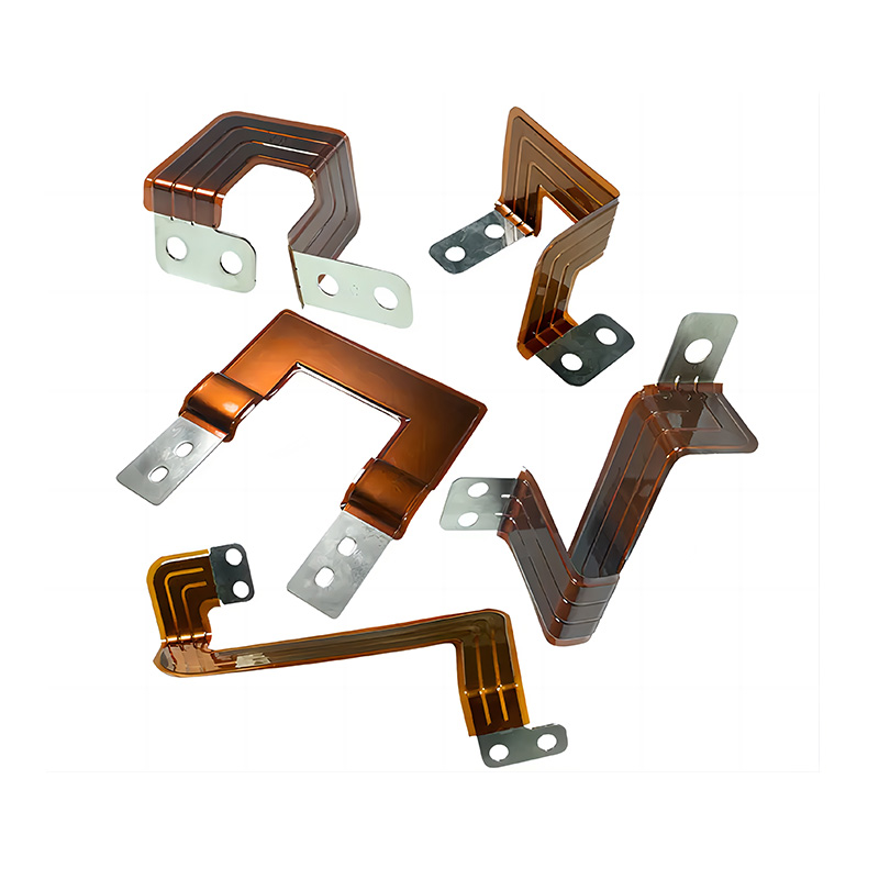
High Current Flexible Busbar Connectors for EV Battery & New Energy Grid
Core Product Advantages
High Electrical Conductivity
The use of high-purity copper enables efficient current transmission and supports the electrical performance required by high-power battery and grid applications. Copper has a proven combination of conductivity, thermal characteristics, mechanical workability, and joining compatibility. When the conductor cross-section is selected correctly, the flexible busbar can carry substantial current while maintaining a compact profile.
Low resistance is particularly important in battery packs and energy storage systems. Even a small resistance value can generate noticeable heat when large currents flow continuously or during short high-power events. Excessive heat can increase cooling requirements, reduce system efficiency, accelerate insulation aging, and create thermal-management challenges. A properly designed copper flexible busbar helps reduce these risks by providing a direct, low-resistance connection.
Excellent Flexibility
Multi-layer copper construction allows individual layers to slide slightly against one another during bending. This design provides a small bending radius and supports flexible wiring in confined spaces. The connector can be shaped during installation or supplied in a preformed configuration according to the customer’s assembly drawings.
Flexibility is not only useful for installation convenience. It can also improve long-term reliability by relieving mechanical stress. In an electric vehicle, the connection may be exposed to continuous vibration, acceleration, braking, and road shock. In an energy storage cabinet, the connection may experience thermal cycling and enclosure movement. A suitable flexible busbar can accommodate these changes more effectively than a rigid conductor.
High-Current Capability
The available current range extends from approximately 50 A to 2,500 A, depending on conductor dimensions, copper layers, terminal design, insulation, cooling conditions, and application requirements. Large cross-sectional areas up to 1,200 mm² can be used for high-power systems that require substantial energy transfer.
Current capacity must always be verified for the actual application. Factors such as ambient temperature, enclosure ventilation, contact resistance, duty cycle, installation orientation, proximity to other heat sources, and permissible temperature rise all influence the final rating. For this reason, a professional supplier should evaluate the complete operating condition rather than selecting a component solely by nominal cross-section.
Low-Profile Construction
Flexible busbar connectors can be manufactured with a flat and compact geometry. This is valuable inside battery modules and power electronics enclosures where space is limited in all three dimensions. A flat connection may fit beneath covers, alongside cell groups, or between structural parts where a round cable would require additional clearance.
A low-profile design can also improve the organization of the electrical system. Shorter and more direct current paths reduce unnecessary routing and can make inspection, maintenance, and thermal management easier. In automated production lines, standardized flat connectors can support repeatable placement and controlled assembly sequences.
Custom Insulation Options
Insulation protects personnel and equipment from unintended electrical contact. It also helps prevent short circuits caused by conductive debris, vibration-related abrasion, incorrect routing, or contact with nearby metal structures. Insulated flexible busbars can be supplied in various colors to support polarity identification, phase identification, assembly control, and visual inspection.
Halogen-free insulation is available for projects that place emphasis on low-emission materials, environmental considerations, or specific fire and safety requirements. Insulation selection should take into account operating temperature, voltage, flexibility, abrasion resistance, chemical exposure, flame behavior, and the installation environment.
Tin-Plated Surface Options
Tin plating can be applied to selected copper surfaces to improve surface protection and support reliable electrical contact. A tin-plated termination may be especially useful where oxidation control, solderability, or compatibility with mating surfaces is important.
The plating thickness, coverage, and treatment should be selected according to the application. High-current connections require careful control of the contact interface because surface condition, flatness, fastening force, and terminal geometry all affect contact resistance. A well-designed plated terminal can help maintain stable performance over the service life of the equipment.
Applications in Electric Vehicle Battery Packs
Electric vehicle battery packs require numerous electrical connections between cells, modules, busbars, contactors, fuses, sensors, battery-management components, and external power terminals. These connections must support high current while operating in a compact enclosure exposed to vibration, temperature variation, and repeated charge-discharge cycles.
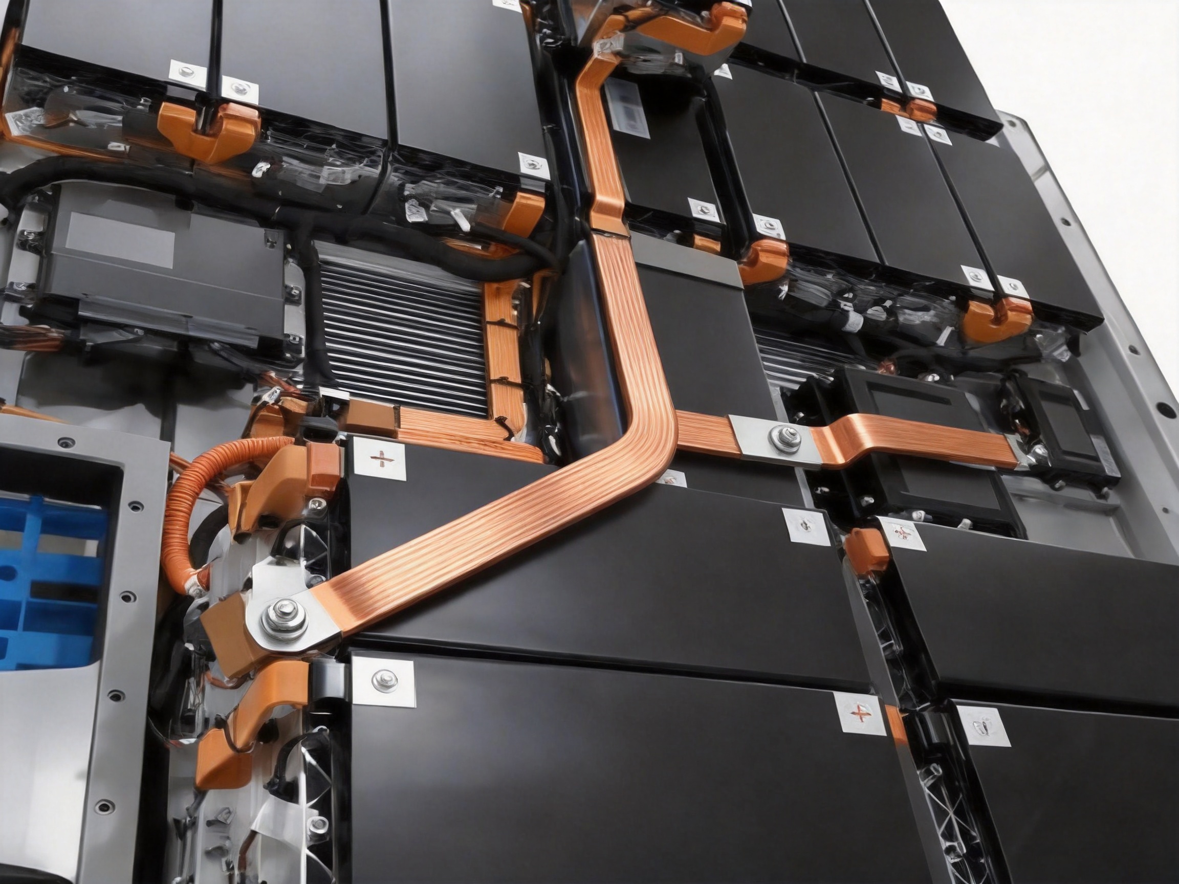
Flexible busbar connectors can be used between battery modules, between modules and main busbars, and between the battery pack and high-voltage distribution components. Their flexible construction helps accommodate module tolerances and reduces the need for rigid alignment between multiple parts.
In an EV battery pack, weight and packaging efficiency are major design considerations. A custom-shaped flexible busbar can follow the natural layout of the pack, reducing excess conductor length and avoiding unnecessary cable loops. The connector can also be designed with openings, terminal offsets, or insulation windows that correspond to the battery housing and service requirements.
Reliability is equally important. The connector must maintain electrical and mechanical performance during charging, acceleration, braking, rapid temperature changes, and vehicle vibration. Flexible construction can reduce stress concentration at the connection points, while suitable insulation helps protect the high-voltage circuit from the surrounding enclosure.
For battery manufacturers and vehicle suppliers, consistency between parts is essential. Repeated production requires stable dimensions, controlled terminal positions, predictable electrical characteristics, and reliable insulation. Precision manufacturing and quality-management procedures are therefore as important as the choice of copper material.
Applications in Energy Storage Systems
Stationary energy storage systems use battery racks, modules, power-conversion systems, protection devices, monitoring units, and distribution equipment. Depending on the architecture, current may flow between individual modules, rack-level busbars, DC combiner units, bidirectional inverters, and external grid interfaces.
Flexible busbar connectors are well suited to these systems because they can accommodate rack assembly tolerances and simplify connections in densely populated cabinets. Their low-profile shape can help preserve airflow and leave space for cooling channels, monitoring equipment, and protective barriers.
Energy storage systems often operate for long periods and may experience frequent charge-discharge cycles. During operation, the temperature of the cells, busbars, terminals, and surrounding enclosure can change. A flexible connection can help reduce mechanical stress caused by thermal expansion and contraction, provided that the product is correctly sized and installed.
Large energy storage projects also benefit from customization. A supplier can manufacture connectors with different lengths, terminal widths, hole diameters, insulation colors, conductor layers, and connection angles. This flexibility supports the requirements of rack manufacturers, containerized storage integrators, commercial storage systems, and industrial backup-power installations.
Applications in New Energy Power Grids and Inverters
Renewable-energy installations frequently combine solar generation, wind power, battery storage, power conversion, and grid-distribution equipment. Inverters and power distribution units may contain high-current DC links, AC bus connections, semiconductor modules, filters, contactors, and protection components.
Flexible busbar connectors can provide short and efficient connections between these elements. Their ability to absorb movement and fit around internal components is useful in inverter cabinets and compact power-conversion assemblies. The low-resistance conductor can also support efficient power transfer between batteries and inverters.
In grid-support applications, equipment may operate under changing load profiles. Peak-power events, rapid charging, frequency regulation, and renewable-energy fluctuations can create repeated current changes. Properly designed flexible busbars help maintain stable electrical connections under these dynamic conditions.
For power distribution, insulated flexible busbars can help improve electrical separation and reduce the risk of accidental contact. Different insulation colors may be used to distinguish positive and negative circuits, phases, functional zones, or service sections.
Material Selection and Technical Configuration
T2 Copper
T2 copper is a widely used conductive material for busbar and electrical connection applications. It offers strong electrical conductivity and can be formed, layered, welded, plated, and machined into many configurations. It is suitable for a broad range of battery and power-distribution applications when the material grade and dimensions meet the project requirements.
Tinned Copper
Tinned copper combines a copper base with a protective tin surface. The tin layer can improve resistance to surface oxidation and support reliable contact in applications where the termination may be exposed to humidity or changing environmental conditions. Tinned copper is also compatible with several joining and termination processes.
Insulating Materials
Insulating materials must be chosen according to the required voltage, temperature, flexibility, flame behavior, chemical exposure, and mechanical conditions. Halogen-free materials can be supplied for projects that require specific environmental or safety characteristics. The insulation can be applied over the conductor while leaving designated terminal areas exposed for electrical connection.
For high-voltage battery systems, insulation design must include sufficient creepage and clearance considerations. The final product should be evaluated within the actual enclosure because nearby metal surfaces, fasteners, protective covers, and cooling structures can influence the electrical safety of the assembly.
Terminal Materials and Surface Treatment
Terminals may be produced from copper or compatible copper alloys and can be supplied with tin plating or other specified surface treatments. The choice depends on current capacity, mating material, joining method, corrosion requirements, and customer specifications.
Terminal flatness, hole position, edge quality, weld integrity, and surface condition are important quality characteristics. A terminal that is electrically conductive but poorly aligned may create installation stress or uneven contact pressure. Precision manufacturing therefore contributes directly to electrical and mechanical performance.
Manufacturing Process and Engineering Strengths
The production of a reliable flexible busbar is a controlled sequence rather than a single fabrication operation. Material preparation, layer arrangement, forming, welding or crimping, machining, surface treatment, insulation, inspection, and packaging must all be coordinated to produce a stable finished part.
Engineering Review and Design Development
Production begins with a review of the customer’s electrical and mechanical requirements. Engineers evaluate current rating, voltage, conductor cross-section, available installation space, bending direction, minimum bending radius, terminal spacing, mounting-hole design, insulation requirements, operating temperature, and expected mechanical movement.
Where necessary, the supplier can transform two-dimensional drawings or three-dimensional models into a manufacturable busbar design. The engineering team may recommend changes to bend locations, terminal transitions, insulation clearance, or welding areas to improve production stability and service reliability.
Design review is particularly important for high-current applications. A connection should not be designed only around the nominal current. Engineers should also consider peak current, continuous current, duty cycle, permissible temperature rise, cooling conditions, and contact resistance. This approach helps prevent under-designed connections and supports more reliable system integration.
Precision Copper Preparation
High-purity copper material is prepared according to the required thickness, width, length, and surface condition. The production team controls material specifications and dimensions before the copper enters the forming or laminating process. Correct preparation ensures that the finished conductor has a consistent cross-sectional area and stable electrical characteristics.
For laminated designs, individual copper layers are cut and aligned according to the product drawing. Layer count and thickness determine the overall cross-section, flexibility, and current capacity. Precise alignment is important because uneven edges or irregular layer positioning can affect terminal welding, insulation coverage, and final assembly.
Layer Assembly and Forming
The copper layers are assembled into a flexible conductive structure. Depending on the product design, the layers may be arranged to support sliding movement during bending. Forming operations create the specified offsets, bends, steps, or terminal transitions.
Controlled forming helps ensure that the connector meets its intended three-dimensional shape without creating excessive work hardening or damage to the copper. The bending sequence must also maintain the required minimum radius. Excessive bending can reduce fatigue life, while insufficient forming accuracy can cause installation difficulty.
Diffusion Welding and Specialized Joining
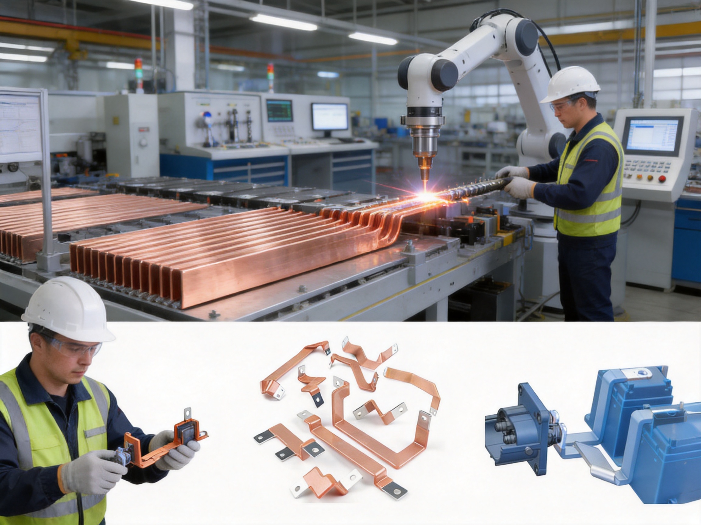
Advanced joining methods are used to create strong and conductive terminal sections. Polymer diffusion welding and laser-related technologies are part of the company’s independently developed process capabilities. These technologies support precision joining and can help produce low-resistance, high-reliability connections for battery and new energy applications.
Diffusion-based welding can create a consolidated connection across multiple copper layers. When properly controlled, it improves current distribution through the terminal area and reduces the risk of internal discontinuities. Laser technology can provide precise energy input and controlled joining zones, which is valuable when working with thin layers, compact terminals, and complex geometries.
Welding parameters must be matched to copper thickness, layer count, terminal design, surface condition, and product geometry. Important process variables may include energy, pressure, time, alignment, and thermal control. Consistent parameter management helps produce repeatable weld quality from batch to batch.
Crimping and Mechanical Termination
Some flexible busbar connectors use crimped terminals instead of welded terminals. Crimping can provide a practical and efficient joining method when the terminal geometry and conductor structure are designed for the process. Proper crimp height, force, position, and tooling are important to achieve a stable mechanical and electrical connection.
Crimped designs can be selected based on customer assembly requirements, equipment compatibility, service conditions, and production volume. The choice between welded and crimped terminals should be made through an engineering evaluation of current, vibration, thermal conditions, available equipment, and applicable standards.
Machining and Terminal Finishing
After forming and joining, terminal areas may be drilled, punched, trimmed, deburred, or otherwise machined to achieve the required dimensions. Hole diameter, center distance, edge distance, terminal width, and surface flatness are controlled according to the drawing.
Accurate machining is essential for smooth installation. Misaligned holes or rough edges can increase assembly time, damage insulation, or create uneven clamping pressure. Finished terminal surfaces are inspected to confirm that they meet the specified dimensional and appearance requirements.
Surface Plating
Tin plating may be applied to the terminal or other specified copper surfaces. The plating process is controlled to achieve suitable coverage and adhesion. A consistent plated surface can improve contact stability and protect the copper from environmental exposure.
Surface treatment is selected based on the electrical interface and service environment. The production team can work with customers to determine whether bare copper, tinned copper, or another specified treatment is appropriate for the project.
Insulation Application
Insulation is applied after the conductive structure and terminal areas have been prepared. The process must ensure that the insulation covers the designated regions without obstructing mounting holes, connection surfaces, or required inspection points.
Insulation thickness, color, adhesion, flexibility, and edge condition are controlled during production. Where a product includes several bends, the insulation must remain intact after forming and during installation. The use of halogen-free insulating material is available when required by the project specification.
Quality Inspection and Testing
A professional manufacturing system includes inspection at multiple stages. Incoming copper material can be checked against grade and dimensional requirements. During production, operators and quality personnel monitor layer alignment, forming accuracy, terminal dimensions, weld appearance, crimp condition, plating, and insulation coverage.
Final testing may include dimensional inspection, visual examination, resistance measurement, terminal pull or mechanical evaluation, insulation inspection, and withstand-voltage testing where applicable. The exact test plan depends on the product design and customer requirements.
Traceability is also important for high-current battery components. Production records can connect material batches, process parameters, inspection results, and shipment information to a specific order. This supports quality analysis, customer service, and continuous improvement.
Advantages Compared with Conventional Connection Solutions
Compared with Rigid Copper Bars
Rigid copper bars are strong and electrically efficient, but they are less tolerant of movement and dimensional variation. They often require precise alignment between connected components. Any mismatch may cause installation stress or require additional brackets, joints, or machining.
Flexible busbar connectors provide greater adaptability. They can be bent or preformed to match the equipment layout, reducing alignment problems and helping absorb vibration and thermal movement. This makes them particularly valuable in vehicle battery packs and modular energy storage equipment.
Compared with Round Cables
Round cables are flexible and widely used, but high-current cable assemblies may require thick insulation, large bending space, separate lugs, and additional support. Cable routing can become difficult in compact enclosures, especially when several high-current connections must be placed close together.
Flat flexible busbars use the available space efficiently and can provide a short, direct connection. Integrated or customized terminals can reduce the number of separate components. The resulting assembly may be easier to inspect and more compatible with automated or semi-automated production.
Compared with Generic Standard Parts
Generic parts may not match the exact terminal spacing, bend orientation, insulation length, or available installation space of a specific battery or power system. A mismatch can lead to field modification, excess stress, longer assembly time, or compromised insulation.
Custom flexible busbars are developed around the customer’s electrical and mechanical requirements. The supplier can adjust cross-section, layer count, length, terminal style, bend angle, hole pattern, plating, insulation color, and other features. This reduces the need for improvised modifications during assembly.
Customization Capabilities
Customization is one of the main advantages of working with a specialized busbar manufacturer. Product development can begin with a drawing, sample, technical specification, or three-dimensional model. Engineering personnel can then confirm the conductor design, terminal arrangement, insulation configuration, and production method.
Typical customization parameters include:
Conductor material: T2 copper, tinned copper, or another approved copper specification.
Conductor cross-section: From compact sections for moderate current to large sections for high-power applications.
Current capacity: Designed according to continuous current, peak current, duty cycle, temperature rise, and cooling conditions.
Length and overall dimensions: Adjusted to match the battery pack, inverter, rack, cabinet, or distribution equipment.
Terminal design: Welded, crimped, drilled, punched, formed, offset, or specially shaped terminals.
Hole pattern: Customized hole diameter, center distance, orientation, edge distance, and mounting arrangement.
Bending geometry: Straight, stepped, offset, angled, multi-bend, or three-dimensional configurations.
Surface treatment: Bare copper, tin-plated copper, or another specified treatment.
Insulation: Standard or halogen-free materials, with different colors, lengths, thicknesses, and exposed terminal areas.
Packaging: Protection against deformation, abrasion, contamination, and moisture during transport and storage.
Customization should be finalized through an engineering review to ensure that the proposed product can be manufactured consistently and installed safely. A clear technical drawing should identify dimensions, tolerances, materials, surface treatment, insulation, and testing requirements.
Technical Reference Table
| Parameter | Available or Typical Range | Design Considerations |
|---|---|---|
| Conductor material | T2 copper or tinned copper | Selected according to conductivity, surface protection, joining method, and environmental conditions |
| Section area | 10 mm² to 1,200 mm² | Determined by current, temperature rise, installation space, and cooling |
| Current rating | 50 A to 2,500 A | Final rating depends on duty cycle, ambient temperature, enclosure, and conductor configuration |
| Operating temperature | -40°C to 125°C | Must be verified against insulation, terminal, and system requirements |
| Withstand voltage | 600 V to 1,000 V | Depends on insulation design, clearance, creepage, and test conditions |
| Connection type | Welded or crimped terminals | Selected according to current, mechanical stress, equipment, and assembly process |
| Insulation | Standard or halogen-free options | Color, thickness, flexibility, flame characteristics, and chemical resistance can be customized |
| Surface treatment | Bare copper or tin-plated surface | Selected according to contact conditions and corrosion-control requirements |
| Compliance targets | RoHS, UL, and IEC-related requirements | Applicable standards should be confirmed for the specific product and market |
Quality, Reliability, and Compliance
High-current conductors are safety-critical components. A defect in a battery busbar can cause overheating, voltage loss, intermittent operation, or damage to connected equipment. Quality control must therefore address both electrical and mechanical characteristics.
Dimensional consistency is necessary for correct assembly. Terminal holes must align with mating components, and bend positions must correspond to the enclosure design. Electrical resistance must remain within the specified limit, while welds and crimps must withstand the mechanical forces expected during installation and operation.
Insulation quality is equally important. The material must remain stable across the specified temperature range and should resist cracking, peeling, abrasion, and deformation under normal service conditions. High-voltage applications require particular attention to insulation coverage, exposed conductive areas, and the spacing between energized parts.
RoHS considerations help control restricted substances in the product. UL and IEC-related requirements may apply depending on the market, system type, voltage level, and customer certification program. Standards should be reviewed at the beginning of the project so that materials, testing, documentation, and production processes can be aligned with the intended application.
A reliable manufacturer should also support sample approval and engineering validation before mass production. Prototype samples allow the customer to check fit, bend direction, terminal alignment, insulation, and installation procedure. Any required design changes can be completed before the production tooling and processes are fully established.
Company Manufacturing and Development Strengths
Zhejiang Zhongyan New Energy Co., Ltd. is a high-tech enterprise focused on new energy conductive components and precision electrical connection products. Its product scope includes high-voltage electrical copper foil soft connections, special-shaped soft connections, battery soft connections, and related conductive components for power transmission, new energy vehicles, rail transit, communications, and energy storage.
The company combines experienced engineers, technical personnel, specialized production equipment, and established manufacturing procedures. This combination supports the complete development process from product design and research to production, testing, and delivery.
Its manufacturing experience is centered on flexible and soft connection technologies. This focus is important because flexible busbars require more than basic copper cutting. The supplier must understand material behavior, layer movement, terminal joining, bending stress, insulation design, and high-current electrical performance.
The company has developed polymer diffusion welding and laser-related technologies for new energy precision components. These process capabilities support the production of connections with low internal resistance and stable mechanical performance. They also help enable complex geometries and customized battery connection designs.
Established in 2022, the company has built its development direction around battery soft connections and other new energy components. According to the supplied company information, its products have been used by leading enterprises including BYD, CATL, and Jaguar. Such supply relationships indicate the importance of consistent production, engineering response, quality control, and delivery performance in the company’s target markets.
The company is also expanding its research and development system across materials science, precision machining, testing, and verification. This integrated approach allows product development to consider the full life cycle of a component rather than treating the busbar as an isolated metal part.
In addition to conductive components, the company is pursuing broader capabilities in lithium battery manufacturing and integrated battery cell and connection-system design. This direction may support customers that require closer cooperation between cells, busbars, battery-management components, and complete battery assemblies.
How to Select the Correct Flexible Busbar
Selecting a busbar should begin with the electrical requirements. The design team should identify continuous current, maximum current, expected duty cycle, system voltage, allowable voltage drop, and permissible temperature rise. Current rating should not be estimated from cross-section alone because installation conditions have a major effect on thermal performance.
The mechanical environment should then be reviewed. Engineers should identify vibration levels, thermal expansion, movement frequency, installation direction, available space, minimum bending radius, and the required service life. If the busbar will be installed in a vehicle or moving assembly, mechanical flexibility and terminal stress deserve special attention.
Terminal requirements must also be defined. Important details include hole diameter, hole spacing, terminal thickness, mating material, fastening method, torque, plating, weld area, and access for tools. Incorrect terminal design can create installation delays even when the conductor itself is correctly sized.
Insulation requirements should include operating voltage, test voltage, environmental exposure, temperature range, flame requirements, abrasion risk, and color coding. Customers should specify which parts of the conductor need to remain exposed and whether the insulation must be halogen-free.
Finally, the customer should confirm compliance, inspection, packaging, and documentation requirements. A complete specification helps prevent ambiguity and ensures that the supplier can quote, prototype, and manufacture the product accurately.
Installation and Service Recommendations
Flexible busbar connectors should be installed according to the approved drawing and assembly instructions. The connector should not be forced into a position that differs significantly from its designed bend direction. Excessive twisting or repeated sharp bending may reduce service life.
Terminal surfaces should be clean and free from oil, dust, oxidation, and foreign material before assembly. Fasteners should be tightened using the specified torque. Under-tightening can increase contact resistance, while over-tightening may deform the terminal or damage the connected component.
The busbar should be supported where necessary, particularly in applications exposed to vibration. However, supports should not restrict the designed flexible movement or create a sharp stress concentration. Insulation should be inspected after installation to confirm that it has not been cut, pinched, or damaged by nearby parts.
During maintenance, technicians should follow the system’s electrical isolation and high-voltage safety procedures. Any connector showing discoloration, deformation, looseness, cracked insulation, or unusual heating should be investigated before the equipment is returned to service.
Sustainability and Lifecycle Considerations
Efficient electrical connections contribute to the overall energy performance of a new energy system. Lower resistance can reduce electrical losses and unwanted heat, particularly in high-current applications operating for long periods. Improved thermal performance may also reduce the burden on cooling equipment.
Copper is a valuable recyclable material, and responsible product design should consider recovery at the end of service life. The use of appropriate insulation and surface treatments can support product performance while allowing future recycling processes to be evaluated according to local requirements.
Long service life is another sustainability factor. A flexible busbar that remains mechanically stable, electrically efficient, and properly insulated can reduce replacement frequency and maintenance requirements. Durable connections also help prevent secondary damage to batteries, inverters, and distribution equipment.
The company’s focus on green energy applications, battery systems, and new energy precision components aligns with the wider transition toward cleaner electricity and lower-carbon transportation. Reliable conductive components are essential to making these systems safe, efficient, and commercially practical.
Frequently Asked Questions
What is a high-current flexible busbar connector?
A high-current flexible busbar connector is a conductive component made from layered or flexible copper, usually with formed or attached terminals and optional insulation. It transmits substantial electrical current while allowing bending, movement, and compensation for installation tolerances.
Why use a flexible busbar instead of a rigid copper bar?
A flexible busbar can accommodate vibration, thermal expansion, and small alignment differences that a rigid bar cannot easily tolerate. It is also easier to route through compact battery packs and power cabinets. The correct choice depends on current, space, mechanical conditions, and the system design.
Why use a flexible busbar instead of a cable?
A flexible busbar provides a flat, low-profile current path and can be customized to fit a specific three-dimensional layout. It may require less routing space than a large round cable and can reduce the number of separate lugs and fastening components.
What copper materials are available?
The standard conductor options include T2 copper and tinned copper. T2 copper provides high conductivity, while tinned copper adds a protective surface that can support oxidation control and reliable contact in suitable environments.
Can the busbar be customized for a specific battery pack?
Yes. Length, width, thickness, layer count, terminal geometry, hole pattern, bend angle, connection direction, surface treatment, insulation material, and insulation color can be customized according to the customer’s drawing and technical requirements.
What current can these connectors carry?
The stated product range supports approximately 50 A to 2,500 A, depending on the conductor section, copper material, insulation, installation conditions, cooling, and duty cycle. The final current rating should be confirmed through engineering review and application-specific evaluation.
Are halogen-free insulation materials available?
Yes. Halogen-free insulating material can be selected when required by the project, customer specification, environmental policy, or applicable safety requirements.
What terminal connection methods are available?
Welded and crimped terminal configurations are available. The appropriate method depends on current, mechanical loads, production equipment, required geometry, and the customer’s assembly process.
Can flexible busbars be used in high-voltage battery systems?
They can be designed for high-voltage battery systems when the conductor, insulation, terminal spacing, creepage, clearance, and testing requirements are correctly specified. Product selection must be based on the complete system design rather than voltage alone.
What operating temperature range is supported?
The supplied technical range is approximately -40°C to 125°C. The actual usable range depends on the selected insulation, terminal configuration, current load, installation environment, and applicable validation requirements.
How does tin plating improve the product?
Tin plating can help protect copper surfaces from oxidation and provide a suitable contact surface for selected mating interfaces. The plating specification should be matched to the electrical, mechanical, and environmental conditions of the application.
What industries use these flexible busbar connectors?
Typical applications include electric vehicle batteries, hybrid vehicle systems, stationary energy storage, new energy power grids, inverters, power distribution equipment, rail transit, communications power systems, and industrial electrical equipment.
How should the busbar be tested before mass production?
Prototype testing may include dimensional inspection, fit verification, resistance measurement, insulation examination, withstand-voltage testing, terminal mechanical evaluation, and thermal assessment. The exact test plan should be established according to the product drawing and application requirements.
What information should be included in an inquiry?
An inquiry should include current and voltage requirements, conductor material, dimensions, terminal drawings, hole pattern, bend geometry, insulation requirements, operating temperature, expected quantity, applicable standards, and delivery requirements. A three-dimensional model or sample can further accelerate engineering review.
What makes a specialized manufacturer different from a general metal fabricator?
A specialized manufacturer understands the interaction between copper conductivity, flexible layer construction, terminal joining, insulation, vibration, thermal cycling, and battery-system integration. It can provide engineering support and process control rather than only cutting or bending metal.
Conclusion
High-current flexible busbar connectors are essential components for modern battery and power-conversion systems. They combine the low resistance and high conductivity of copper with the flexibility required by compact, vibrating, and thermally dynamic equipment. Their ability to accommodate custom shapes, terminal layouts, surface treatments, and insulation systems makes them suitable for electric vehicles, energy storage systems, inverters, new energy grids, and industrial power distribution.
The product range described here supports T2 copper and tinned copper conductors, section areas from 10 mm² to 1,200 mm², current ratings from 50 A to 2,500 A, operating temperatures from -40°C to 125°C, and insulation withstand voltages from 600 V to 1,000 V. Welded and crimped terminals, halogen-free insulation, tin-plated surfaces, and customized dimensions provide flexibility for different project requirements.
The manufacturing strength behind the product is equally important. Engineering review, precision copper preparation, multi-layer assembly, controlled forming, diffusion welding, laser-related joining, terminal machining, surface treatment, insulation application, and multi-stage inspection all contribute to reliable performance. Zhejiang Zhongyan New Energy Co., Ltd. combines these capabilities with experience in battery soft connections and new energy conductive components.
For customers developing electric vehicle battery packs, stationary storage systems, or high-power electrical equipment, a custom flexible busbar can improve packaging efficiency, simplify assembly, reduce connection resistance, and support long-term system reliability. Careful design collaboration and application-specific validation are the best ways to ensure that the final connector meets the required electrical, mechanical, thermal, and safety performance.
References
1. International Electrotechnical Commission, standards and technical guidance relating to low-voltage electrical assemblies, insulation coordination, and electrical safety.
2. Underwriters Laboratories, safety requirements and evaluation principles for battery systems, power equipment, and electrical connection components.
3. Restriction of Hazardous Substances requirements for electrical and electronic equipment materials.
4. Copper Development Association, technical publications on copper conductivity, busbar design, current-carrying capacity, and thermal performance.
5. Battery engineering literature covering electric vehicle battery-pack architecture, high-voltage distribution, thermal cycling, vibration, and connection reliability.
6. Power electronics engineering references covering inverter bus connections, low-resistance conductors, thermal management, and energy storage system design.
Product: High Current Flexible Busbar Connectors for EV Battery & New Energy Grid

Driven by the development of new energy and aiming for "zero carbon".
Copyright © Zhejiang Zhongyan New Energy Co., Ltd. All Rights Reserved.
