 English
 Español

Halogen-Free Insulated Soft Busbar for Safer, High-Performance Power Distribution
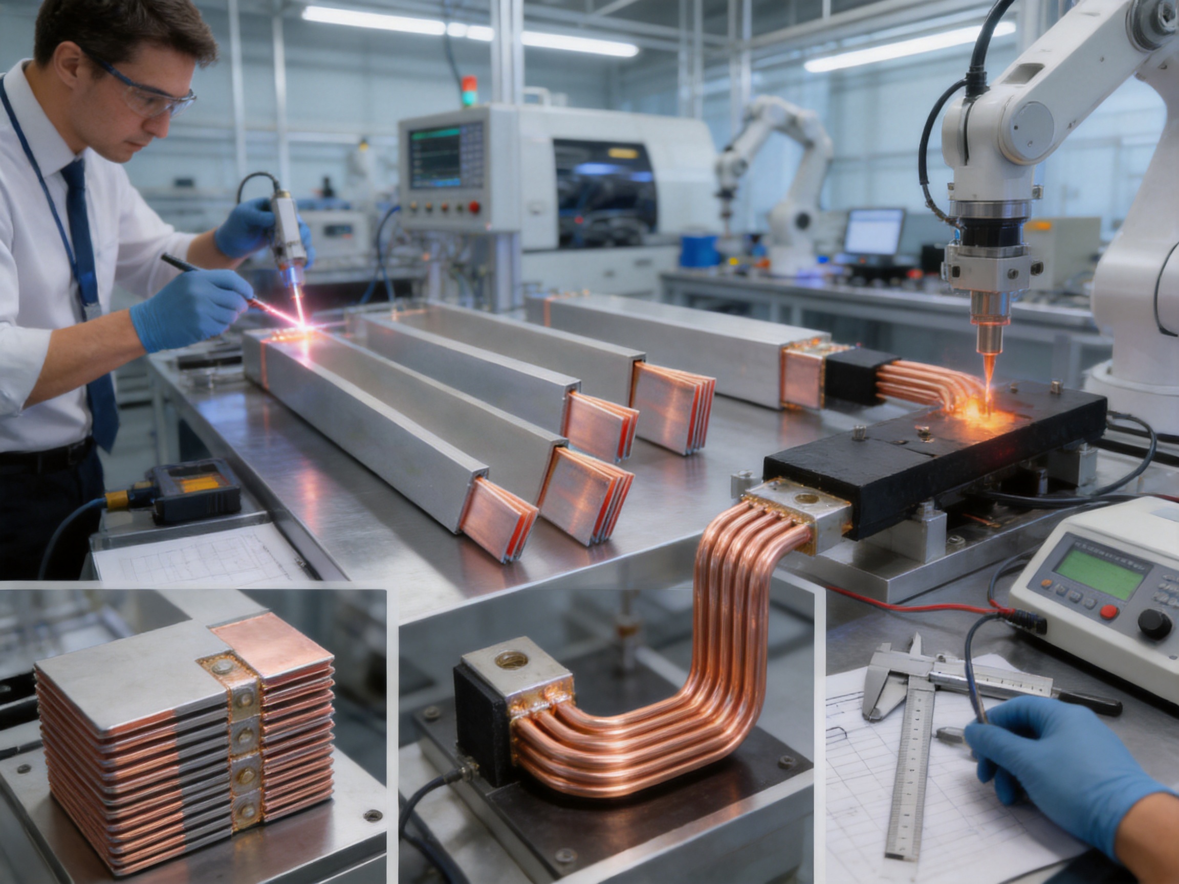
As electrical systems become more compact, powerful, and environmentally conscious, the demand for reliable high-current connection components continues to grow. Electric vehicles, battery energy storage systems, photovoltaic equipment, rail transit, industrial power supplies, and data centers all require conductors that can carry substantial current while occupying minimal space. At the same time, system designers are paying closer attention to fire safety, smoke generation, material compliance, electromagnetic layout, vibration resistance, and ease of installation.
The halogen-free insulated soft busbar is designed to address these combined requirements. It uses a multilayer soft copper conductor produced through stacking and welding, followed by an insulation coating or hot-pressing process. The result is a flexible, flat, high-current connection component with an insulated surface and strong adaptability to three-dimensional equipment layouts.
Compared with conventional rigid copper bars, large cable assemblies, and ordinary insulated conductors, this product offers a practical balance of current-carrying capability, flexibility, insulation performance, space efficiency, and environmental safety. Its structure is particularly suitable for applications in which high current, restricted installation space, repeated vibration, thermal cycling, and demanding fire-safety requirements occur at the same time.
The product is manufactured by Zhejiang Zhongyan New Energy Co., Ltd., a high-tech enterprise specializing in new energy conductive components and precision electrical connections. With experience in copper foil soft connections, battery soft connections, special-shaped flexible connections, polymer diffusion welding, laser processing, testing, and customized manufacturing, the company provides solutions for power transmission and distribution, electric vehicles, rail transit, communications, and energy storage.
1. Understanding the Halogen-Free Insulated Soft Busbar
A busbar is a conductive component used to distribute or connect electrical power. Traditional busbars are often made from rigid copper or aluminum profiles. These products are effective in fixed layouts, but rigid components can become difficult to install when connection points are not perfectly aligned. They may also require additional joints, brackets, insulating barriers, or cable sections to accommodate movement and thermal expansion.
A soft busbar uses multiple thin copper layers rather than one thick, inflexible metal profile. These layers are stacked and joined to form a low-resistance conductive path. Because the individual layers can move slightly relative to one another, the finished component can be bent, twisted, or formed within a defined installation range. This flexibility helps compensate for dimensional tolerances and simplifies connections between batteries, inverters, switching equipment, power modules, and other electrical assemblies.
The halogen-free version adds an insulation system designed to minimize the release of corrosive or hazardous halogen-containing gases during fire conditions. Depending on the application specification, the insulation system may use a silicone compound, TPE, or another qualified halogen-free material. The provided technical information also identifies PVC and TPE as available insulation categories. Because material formulation and compliance requirements can vary by project, the final insulation material should be confirmed during technical approval and product specification review.
The basic construction includes an electrolytic copper conductor, commonly based on T2 copper with a copper content of at least 99.95 percent. The conductor may be supplied with a bare copper surface or a tin-plated surface. An insulating layer is then applied by coating, lamination, or hot pressing according to the required structure, dimensions, dielectric rating, temperature range, and environmental conditions.
This combination of layered copper and engineered insulation gives the product a distinct position between a conventional rigid busbar and a flexible cable. It retains the low-resistance characteristics of a flat copper conductor while offering improved routing flexibility and a more compact form than many conventional cable assemblies.
2. Why Halogen-Free Insulation Matters
Electrical equipment installed in enclosed spaces must be evaluated not only for normal operation but also for abnormal conditions such as overheating, arcing, short circuits, and fire. In a fire, some insulation materials can produce dense smoke or corrosive gases. These emissions can reduce visibility, damage sensitive electronic equipment, complicate evacuation, and create additional hazards for personnel and emergency responders.
Halogen-free insulation is intended to reduce these risks. When properly formulated and tested, it avoids the use of halogen-based flame-retardant systems and is designed to limit the generation of corrosive halogen gases. This characteristic is important in battery packs, rail vehicles, data centers, public transportation systems, power rooms, and other locations where smoke and corrosive emissions are major safety concerns.
The product is positioned for compliance-oriented applications involving RoHS requirements and IEC 60754-related evaluation of gases evolved during combustion. Compliance should always be verified against the exact material, production batch, construction, and applicable customer standard. However, the design direction is clear: the insulation system is intended to combine electrical reliability with improved environmental and fire-safety performance.
Low-smoke behavior is also valuable in high-density equipment. A compact energy storage cabinet may contain many battery modules, busbars, contactors, fuses, sensors, and control boards. If a fault occurs, reducing smoke and corrosive emissions can help protect adjacent components and improve the conditions for inspection and maintenance.
For rail transit and electric vehicles, the advantages are equally significant. Vehicles carry passengers or operators in enclosed compartments, and electrical systems are exposed to vibration, acceleration, temperature changes, and limited ventilation. A flexible busbar with flame-retardant, low-smoke, halogen-free insulation can support a safer overall system design when combined with appropriate overcurrent protection and enclosure engineering.
3. Structure and Manufacturing Principle
3.1 Multilayer Copper Conductor
The conductor is formed from multiple thin copper sheets or foils arranged in a stacked configuration. The reference design identifies a copper sheet thickness of approximately 1 millimeter, although the final layer count, width, length, and terminal geometry may be customized according to current, voltage drop, installation space, and mechanical requirements.
Layered construction gives the conductor a combination of electrical and mechanical advantages. A single thick copper bar has good conductivity but limited flexibility. A group of thin copper layers can provide a similar effective conductive cross-section while allowing controlled movement between layers. This makes the busbar easier to bend and reduces the force transmitted to terminals, studs, battery posts, and connected components.
The use of electrolytic T2 copper supports low electrical resistance and stable current conduction. With copper content of at least 99.95 percent, the material is suitable for applications requiring dependable conductivity and consistent processing performance. Bare copper can be selected where direct conductivity and economical processing are priorities, while tin-plated copper may be selected for improved surface compatibility, solderability, contact stability, or resistance to certain environmental conditions.
3.2 Welding and Joining
The stacked copper layers are joined using controlled welding and related precision processes. Proper joining is essential because the interface between layers must maintain low resistance and sufficient mechanical strength. In high-current applications, an inconsistent joint can produce localized heating, voltage loss, and long-term reliability problems.
Manufacturing control includes alignment of the copper layers, control of welding energy, management of joint geometry, inspection of the welded region, and verification of electrical continuity. Depending on the design, specialized welding, diffusion welding, laser processing, or other joining methods may be used. The objective is to produce a stable conductive assembly that remains reliable during bending, vibration, temperature cycling, and repeated operation.
Zhejiang Zhongyan New Energy has developed experience in polymer diffusion welding and laser technology for new energy precision components. These capabilities support the production of low-resistance, high-reliability soft connections and allow the company to work with complex terminal shapes and customized connection structures.
3.3 Insulation Coating and Hot Pressing
After the conductive structure is prepared, the insulation layer is applied through a controlled coating, laminating, or hot-pressing process. The insulation must cover the required surfaces uniformly and remain securely bonded to the conductor during bending and thermal expansion.
The reference product information specifies an insulation thickness of approximately 2 millimeters with a tolerance of plus or minus 0.2 millimeters. The final thickness may vary by electrical rating, mechanical geometry, creepage and clearance requirements, and customer specification. Uniform thickness is important because thin or poorly bonded areas can reduce dielectric performance and create weak points during installation.
The listed insulation characteristics include a dielectric strength of approximately 20 kilovolts per millimeter, a maximum continuous voltage of up to 1,000 volts AC or 1,500 volts DC, low smoke, flame retardancy, high UV resistance, high ozone resistance, and self-extinguishing behavior associated with UL 94 V-0 performance. These values should be treated as reference specifications and confirmed for the final product configuration through formal testing and documentation.
3.4 Forming and Finishing
Flexible busbars may be supplied in straight, bent, stepped, offset, or three-dimensional forms. Terminal areas can be shaped to match battery posts, copper plates, contactors, power modules, or other connection points. Holes, slots, bends, insulation-free terminal zones, and protective edge treatments may be produced according to approved drawings.
Forming accuracy is important because the busbar should install without excessive force. A properly designed part reduces stress on the connected equipment and can shorten assembly time. It also reduces the need for field bending, which may otherwise damage insulation or produce an unsuitable bend radius.
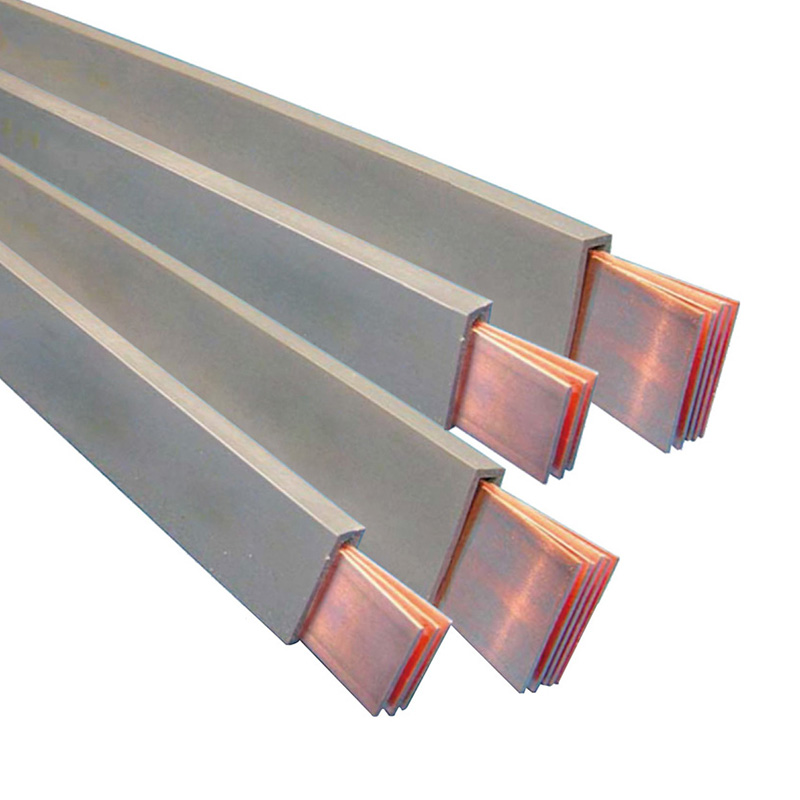
Halogen-Free Insulated Soft Busbar
4. Core Technical Advantages
4.1 High Current Density in a Compact Form
The flat conductor geometry provides a large effective conductive area within a relatively thin profile. Compared with a group of round cables, a flat busbar can use available enclosure space more efficiently. It can be routed along battery modules, between power electronics, or across cabinet compartments while maintaining a controlled shape.
The flat structure also supports heat dissipation. A broad conductor surface can transfer heat more effectively to the surrounding environment than a tightly packed cable bundle. Better thermal behavior can help designers manage continuous current, short-duration overloads, and localized heating. Actual current capacity depends on conductor size, ambient temperature, installation orientation, airflow, insulation material, duty cycle, allowable temperature rise, and terminal design.
High current density does not mean that all installations can use the same rating. Each application should be evaluated through electrical and thermal calculations, prototype testing, and, where required, type testing. The advantage of the product is that its geometry gives engineers more design flexibility when developing a compact high-current connection.
4.2 High Flexibility and Small Bend Radius
The multilayer copper structure allows the busbar to bend within a controlled radius. This feature is useful when battery terminals, inverter terminals, and distribution points are arranged at different heights or positions. The busbar can accommodate modest misalignment without introducing the same level of mechanical stress associated with a rigid bar.
Flexibility is also beneficial during equipment assembly and maintenance. A flexible busbar may be positioned around structural members, cooling channels, fuses, contactors, and sensor wiring. In some designs, it can replace several rigid pieces and intermediate connectors, reducing the number of joints and potential failure points.
The product should not be bent beyond its specified radius or repeatedly flexed without a suitable mechanical design. Flexibility improves installation adaptability, but it does not eliminate the need for strain relief, controlled routing, protection against abrasion, and correct fastening.
4.3 Reliable Insulation
The insulated surface helps prevent accidental contact, short circuits, and arc-over between adjacent conductive parts. It can reduce the need for separate insulating sleeves, barriers, and protective wraps. This is particularly useful in high-voltage battery packs and compact power cabinets, where available space is limited and multiple conductors are positioned close together.
The combination of insulation thickness, dielectric strength, flame retardancy, and environmental resistance supports use in demanding conditions. Silicone-based insulation may be selected for broad temperature performance and flexibility, while TPE or other qualified systems may be selected for specific mechanical, chemical, or processing requirements. The correct material depends on the operating environment and customer standard.
4.4 Temperature Capability
The reference information indicates an operating temperature range of approximately minus 50 degrees Celsius to 280 degrees Celsius, with short-time resistance up to approximately 315 degrees Celsius for the stated insulation system. Such a wide range can be useful in battery compartments, power electronic equipment, rail vehicles, outdoor energy systems, and industrial equipment exposed to thermal cycling.
Temperature capability must be considered at the system level. The maximum allowable temperature may be limited by the copper conductor, terminal plating, connected insulation, fasteners, nearby plastics, battery housing, or customer safety requirements. A product can have a high material temperature rating while the complete assembly requires a lower operating limit. For this reason, thermal validation should include the entire connection system rather than the insulation alone.
4.5 Resistance to UV, Ozone, and Environmental Stress
Outdoor photovoltaic systems, wind power equipment, charging infrastructure, and transportation systems may experience sunlight, ozone, humidity, dust, vibration, and temperature changes. The stated insulation characteristics include very high resistance to UV and ozone, which can help preserve surface performance over time when the material is correctly selected and processed.
Environmental durability also depends on installation details. The busbar should be protected from sharp edges, incompatible chemicals, excessive compression, water accumulation, and mechanical damage. Where the product is used outdoors or in aggressive industrial environments, customers should confirm chemical resistance, ingress protection, salt spray performance, and long-term aging requirements.
4.6 Low Smoke and Flame Retardancy
The insulation is designed to provide low-smoke and flame-retardant performance. The stated self-extinguishing characteristic associated with UL 94 V-0 indicates that the material is intended to resist continued burning under the relevant test method. Such performance can support safer equipment design, but it should not be interpreted as making the complete assembly fireproof.
System-level fire safety also depends on cell chemistry, enclosure construction, spacing, thermal management, protective devices, ventilation, fault detection, and emergency procedures. The busbar contributes to the safety architecture by reducing the risk associated with insulation ignition and corrosive smoke, but it must be used as part of a complete protection strategy.
5. Comparison with Conventional Connection Solutions
The most appropriate comparison is not simply between one product and another supplier. It is between different connection architectures and their suitability for a particular application. The halogen-free insulated soft busbar provides several advantages over conventional rigid bars, unbundled cables, and standard insulation systems, while each alternative may remain suitable for specific circumstances.
| Connection solution | Typical strengths | Common limitations | Advantages of the halogen-free soft busbar |
|---|---|---|---|
| Rigid copper busbar | High conductivity, strong mechanical support, simple fixed geometry | Limited flexibility, difficult alignment, may require multiple sections and insulating barriers | Improved routing flexibility, easier tolerance compensation, fewer mechanical constraints |
| Round cable assembly | Flexible routing, widely available, suitable for many general connections | Requires lugs, sleeves, clamps, and bend space; cable bundles may occupy more volume | Flat profile, high current density, integrated insulation, compact installation |
| Uninsulated copper strap | Simple construction, good conductivity, economical in protected areas | Requires external insulation and greater protection against accidental contact | Integrated insulation, improved touch protection, lower assembly complexity |
| Ordinary insulated conductor | General-purpose electrical insulation | May not meet halogen-free, low-smoke, high-temperature, or compact-layout requirements | Designed for environmentally sensitive, high-temperature, and safety-critical applications |
| Multiple rigid connectors | Can accommodate complex layouts through separate components | More joints, higher assembly time, greater potential for resistance and loosening | Potentially fewer interfaces and a more integrated conductive path |
The principal competitive advantage is integration. The product combines the conductor, flexibility, insulation, and customized geometry in one engineered component. This can simplify the bill of materials and reduce the number of separate protective parts required during assembly.
Another advantage is design adaptability. Instead of forcing the equipment layout to conform to a rigid busbar, the busbar can be designed around the equipment. This is valuable in battery packs, where cell arrangement, cooling channels, contactors, service disconnects, sensors, and enclosure constraints must all be considered simultaneously.
The product can also reduce installation variability. A preformed and insulated busbar may be installed in a defined orientation, whereas a field-assembled cable set may require manual routing, stripping, crimping, insulation wrapping, and final inspection. Reduced manual processing can improve consistency when production volumes are high.
6. Application Areas
6.1 New Energy Vehicles and Power Batteries
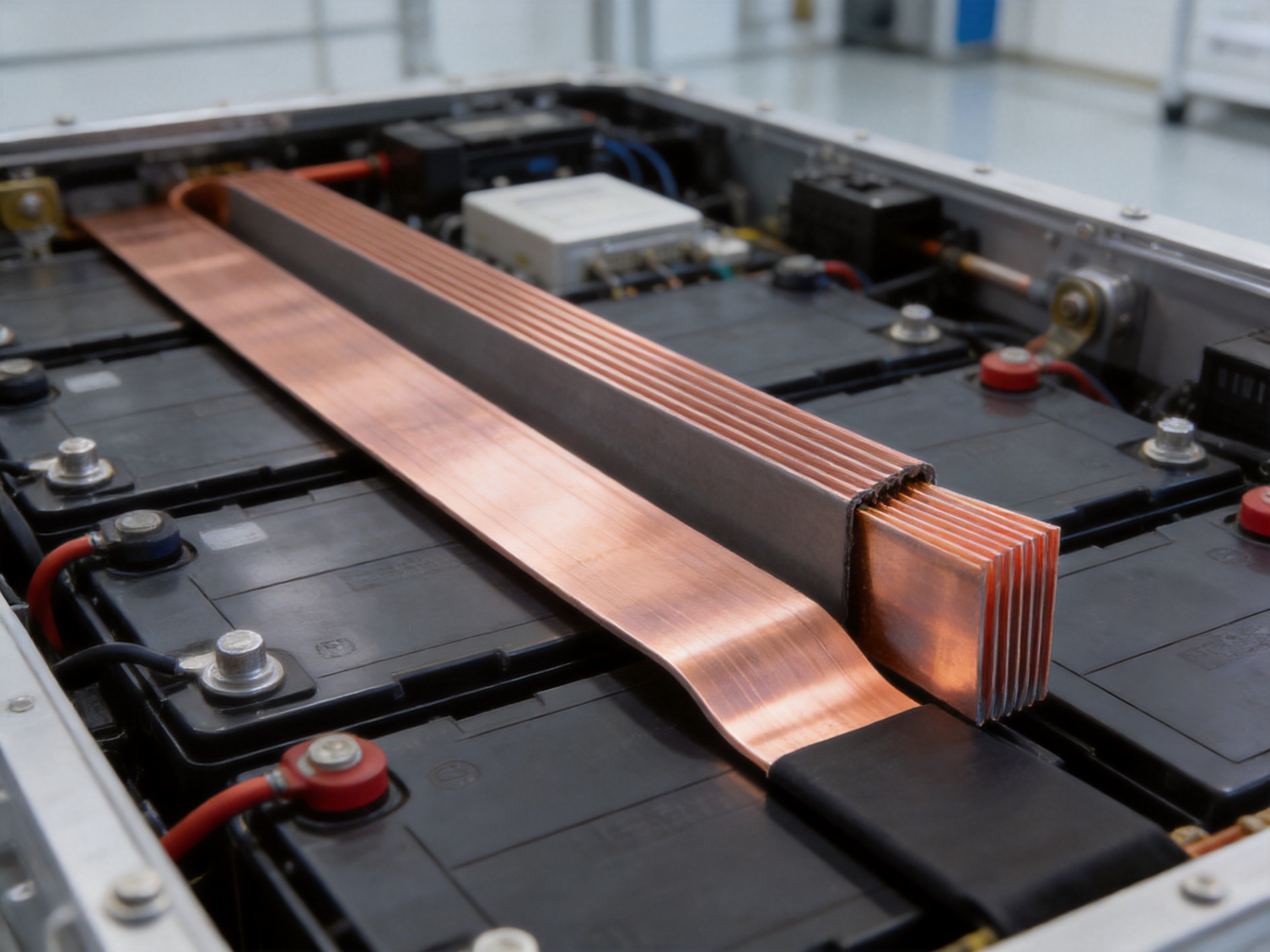
Electric vehicles use high-voltage battery packs, inverters, motor controllers, charging systems, and distribution units. These components must handle substantial current while fitting into limited spaces. The halogen-free soft busbar can be used for internal battery connections, module-to-module links, high-voltage distribution paths, and connections between battery packs and power electronics.
Its flexibility helps absorb dimensional variation and vibration. Its insulation supports high-voltage separation, while its flat shape helps reduce the space occupied by connection hardware. Low-smoke and halogen-free characteristics are particularly relevant in enclosed vehicle compartments.
In battery packs, the busbar design must be coordinated with cell spacing, thermal propagation barriers, monitoring circuits, fuses, contactors, service disconnects, and enclosure requirements. Terminal geometry and insulation-free zones must be precisely defined to ensure that the busbar is easy to assemble and does not interfere with adjacent components.
6.2 Energy Storage Systems
Energy storage systems contain battery racks, modules, power conversion systems, monitoring equipment, contactors, fuses, and control units. Internal connections must support continuous current, short-duration power demands, maintenance access, and reliable operation over long service periods.
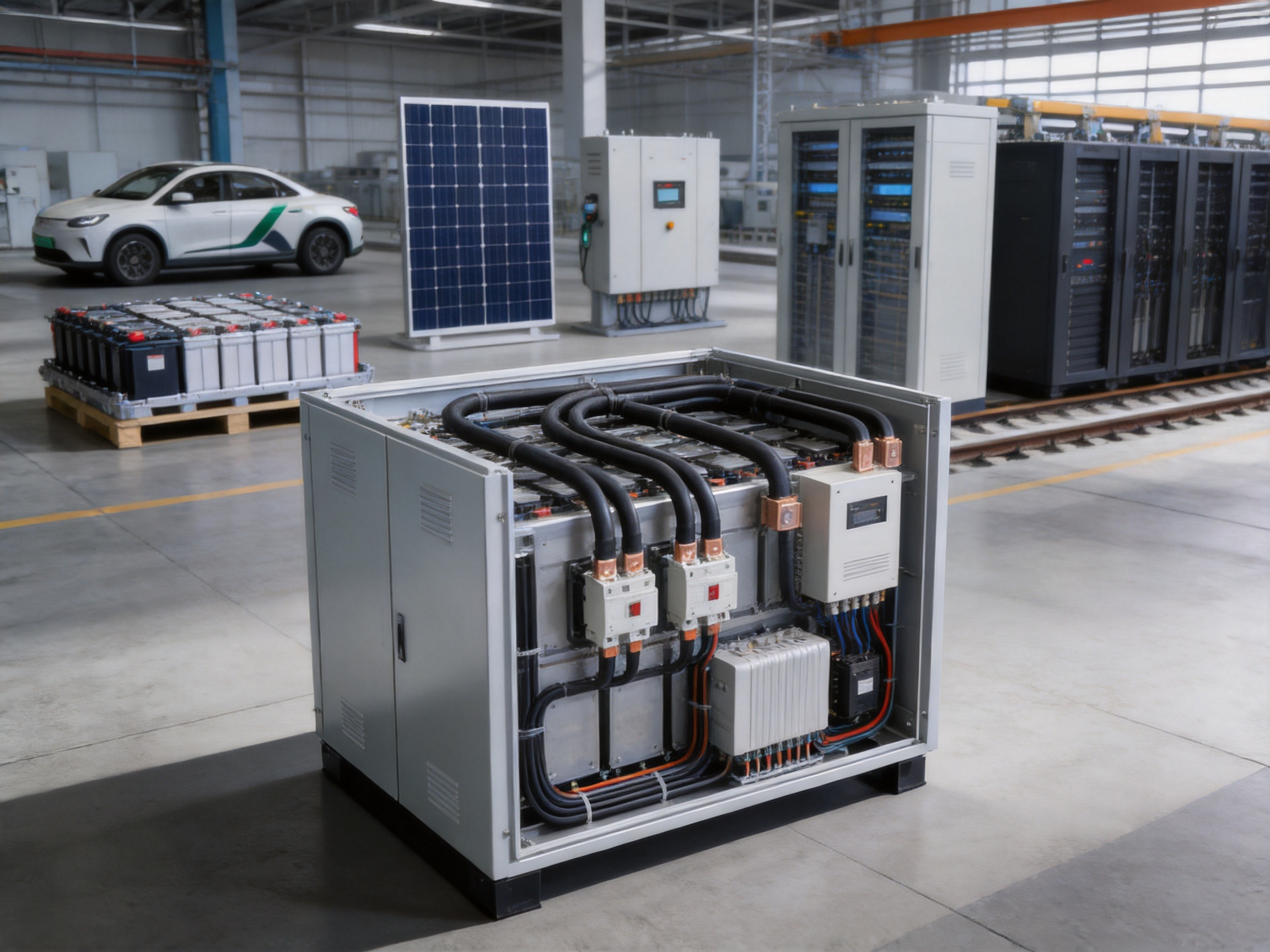
The halogen-free insulated soft busbar is suitable for connections inside battery clusters and energy storage cabinets where high current, compact routing, and low-smoke performance are required. The product can be customized to connect battery modules at different elevations or to route around structural and cooling components.
For stationary storage, the design team should evaluate continuous current, peak current, temperature rise, enclosure ventilation, insulation coordination, creepage distance, short-circuit forces, and service procedures. The busbar can contribute to a clean internal layout and may reduce the number of separate flexible cables and protective sleeves.
6.3 Photovoltaic and Wind Power Equipment
Photovoltaic inverters, combiner boxes, and power conversion systems often require compact, reliable internal conductors. The busbar can be used where high-current paths must pass through a confined enclosure or connect components with limited alignment tolerance.
Wind power equipment may experience vibration, temperature variation, and challenging service conditions. Flexible layered copper helps reduce mechanical stress at connection points, while the insulation system can be selected for resistance to UV, ozone, and temperature exposure where appropriate.
Outdoor applications require careful attention to sealing, condensation, pollution degree, corrosion, and mechanical protection. The busbar should be integrated with the enclosure and supported so that it does not experience unsupported movement or contact with abrasive surfaces.
6.4 Rail Transit and Electric Buses
Subways, high-speed trains, electric buses, and other rail vehicles use electrical systems that must withstand vibration, shock, acceleration, and repeated thermal cycling. Fire and smoke performance is also highly important because passengers may occupy enclosed spaces for extended periods.
A halogen-free, low-smoke soft busbar can support safer power distribution in vehicle electrical cabinets, traction systems, auxiliary power units, and battery compartments. Its flexibility can simplify installation in areas where vehicle structures and equipment frames move slightly relative to one another.
Rail applications often involve demanding fire, smoke, toxicity, vibration, and environmental standards. The final product must therefore be tested and documented according to the relevant vehicle standard and customer specification. Material compliance for one industry does not automatically establish compliance for every rail or transportation standard.
6.5 Industrial Power Equipment
Industrial equipment such as UPS systems, high- and low-voltage distribution cabinets, frequency converters, motor drives, and large power supplies often requires high-current internal connections. Traditional rigid bars may be effective in large fixed cabinets, but flexible insulated busbars can provide advantages in compact modules, movable assemblies, and equipment with complex internal routing.
The integrated insulation can reduce the need for separate barriers. The flexible construction can simplify installation between capacitors, switches, busbar supports, power semiconductors, and terminal blocks. For maintenance-intensive equipment, a clean and accessible connection layout can also support faster inspection and replacement.
6.6 Data Centers and Server Power Systems
Data centers require dependable power distribution and careful control of fire risk. High-density power supplies, uninterruptible power systems, rack-level distribution, and battery backup equipment may all benefit from compact, low-smoke, halogen-free connection components.
The flat profile can help maximize cabinet space and support organized power routing. Because data centers contain sensitive electronic equipment, minimizing corrosive smoke and reducing unnecessary cable congestion can be valuable during abnormal events. The product should be selected together with suitable protection devices, enclosure systems, and maintenance procedures.
7. Manufacturing Strengths and Quality Management
7.1 Specialized Technical Focus
Zhejiang Zhongyan New Energy focuses on new energy conductive components rather than treating soft busbars as a general-purpose commodity. Its product scope includes high-voltage electrical copper foil soft connections, special-shaped soft connections, battery soft connections, and other precision electrical components.
This specialization supports a deeper understanding of the practical issues that affect high-current connections: resistance at welded interfaces, current distribution, heat generation, terminal stress, insulation geometry, battery pack assembly, vibration, and long-term reliability.
7.2 Engineering and Customization Capability
Soft busbars are rarely identical from one project to another. Current level, terminal position, bend direction, hole pattern, insulation color, exposed copper area, mounting method, and environmental conditions may all vary. A supplier must therefore provide more than a standard catalog dimension.
The company brings together experienced engineers and technical personnel with capabilities covering product design, research and development, manufacturing, testing, and solution development. This allows customer drawings to be reviewed for manufacturability and converted into practical production specifications.
Customization may include copper thickness, layer count, overall width, length, bend radius, terminal dimensions, hole and slot geometry, surface treatment, insulation material, insulation thickness, color, and packaging. Before mass production, the design should be confirmed through drawings, samples, electrical validation, mechanical inspection, and applicable compliance testing.
7.3 Advanced Joining Technologies
Electrical resistance at a connection interface can significantly affect temperature rise and service life. The company’s experience with polymer diffusion welding and laser technology supports the production of precise conductive components with stable interfaces and complex geometries.
Laser processing can be useful for controlled joining, fine features, and special-shaped parts. Diffusion-related technologies can support strong, low-resistance connections between suitable materials under controlled process conditions. The selected technology depends on conductor thickness, geometry, production volume, mechanical requirements, and customer quality standards.
7.4 Integrated Development and Verification
The company is developing a research and development system covering materials science, precision machining, testing, and verification. This integrated approach is important because busbar performance depends on the interaction between copper, insulation, joining methods, forming processes, and the application environment.
Engineering verification may include dimensional inspection, electrical resistance measurement, dielectric testing, insulation thickness measurement, bending evaluation, temperature-rise testing, tensile or peel testing where applicable, flame testing, environmental aging, and visual inspection. The precise test program should be established according to the customer specification and applicable standards.
7.5 Stable Production and Consistency
For high-volume battery and energy equipment projects, consistency is as important as prototype performance. Variations in layer alignment, weld quality, insulation thickness, terminal position, or bend angle can create assembly problems and uneven electrical behavior.
Modern production and quality management systems help control these variables. Process instructions, inspection checkpoints, material traceability, equipment maintenance, operator training, and corrective-action procedures all contribute to consistent output.
The company’s experience in supplying precision components to leading enterprises in the new energy sector demonstrates its orientation toward demanding industrial applications. Customer-specific qualification remains necessary, but established experience with high-reliability battery and electrical components provides a useful foundation for new projects.
8. Reference Technical Data
| Item | Reference specification |
|---|---|
| Conductor material | T2 electrolytic copper |
| Copper content | At least 99.95 percent |
| Copper surface options | Bare copper or tin-plated copper |
| Typical copper sheet thickness | Approximately 1 millimeter per sheet |
| Insulation material options | Silicone compound, TPE, or other approved material; PVC and TPE are listed in the technical data |
| Insulation color | Black as the reference color |
| Insulation thickness | Approximately 2 millimeters plus or minus 0.2 millimeters |
| Operating temperature | Approximately minus 50 degrees Celsius to 280 degrees Celsius |
| Short-time temperature | Up to approximately 315 degrees Celsius for the stated system |
| Dielectric strength | Approximately 20 kilovolts per millimeter |
| Maximum continuous voltage | Up to 1,000 volts AC or 1,500 volts DC, subject to design validation |
| Flame behavior | Self-extinguishing characteristic associated with UL 94 V-0 performance |
| Elongation | Approximately 400 percent minimum for the stated insulation material |
| Tear resistance | Approximately 20 kilonewtons per meter minimum |
| Environmental properties | Halogen-free design, low smoke, UV resistance, ozone resistance |
The data in this table should be used as a reference for preliminary design. Final specifications depend on the selected conductor size, number of layers, insulation formulation, terminal structure, production process, and customer test requirements. A formal technical data sheet and approved drawing should govern production and acceptance.
9. Design and Installation Considerations
Correct product selection begins with the electrical load. Engineers should determine continuous current, peak current, overload duration, expected duty cycle, ambient temperature, allowable temperature rise, and permissible voltage drop. The conductor cross-section and layer configuration should then be selected accordingly.
The connection layout should account for bend radius and terminal alignment. The busbar should be installed without sharp folding, twisting beyond the specified range, or excessive tensile loading. Unsupported spans should be minimized, especially in systems subject to vibration or short-circuit forces.
Terminal fasteners must be tightened according to the approved assembly specification. Excessive torque can damage the terminal area or connected equipment, while insufficient torque can increase contact resistance and produce heat. Where a tin-plated surface is used, compatibility with the mating terminal and any required surface preparation should be confirmed.
Insulation should be inspected after forming and installation. Scratches, cuts, compression marks, exposed conductor areas, or improper clearance can compromise dielectric performance. If field modifications are unavoidable, they should be carried out only according to approved procedures.
Clearance and creepage distances must be evaluated at the system level. The insulation on the busbar does not automatically replace all required barriers or spacing. Pollution degree, condensation, altitude, voltage waveform, transient overvoltage, and enclosure design may influence the final insulation coordination.
For battery applications, the busbar should be coordinated with cell monitoring and protection systems. Current paths, service disconnects, fuses, contactors, and emergency isolation devices should be reviewed together. The soft busbar is a conductive component and should not be considered a substitute for an appropriately designed battery protection architecture.
10. Sustainability and Environmental Value
The halogen-free design supports the growing demand for electrical products with improved environmental characteristics. By reducing reliance on halogen-containing insulation systems and supporting low-smoke behavior, the product can help equipment manufacturers meet sustainability objectives and material compliance requirements.
Copper is also a widely recyclable conductive material. At the end of the equipment life cycle, copper recovery may be possible when the product is separated and processed through appropriate recycling systems. The environmental benefit depends on the complete material composition, manufacturing energy, product service life, and recycling route.
Long service life is another important sustainability factor. A durable busbar that maintains stable electrical and insulation performance can reduce replacement frequency, maintenance interruptions, and material consumption. Reliability therefore contributes to environmental performance as well as operating efficiency.
The company’s focus on green energy, energy storage, electric mobility, and precision conductive components aligns the product with sectors that support lower-carbon power generation and transportation. Its broader development direction includes battery cell manufacturing and integrated battery cell and connection system design, creating opportunities for closer coordination between energy storage technology and electrical interconnection.
11. Why Choose a Specialized Manufacturer
A specialized manufacturer can provide more value than a supplier offering only standard copper parts. The soft busbar must be designed around the customer’s electrical, mechanical, thermal, environmental, and assembly requirements. Small details such as a terminal offset, a clearance notch, an insulation transition, or a defined bend can determine whether the product installs efficiently and performs reliably.
Zhejiang Zhongyan New Energy combines material selection, copper processing, welding, laser technology, insulation forming, customization, and testing within a focused new energy component business. This integrated capability helps shorten communication cycles between design and production.
The company’s technical team can participate during the early design stage, when decisions about current capacity, terminal structure, bending, insulation, and assembly access are still flexible. Early engineering involvement can reduce later redesign, tooling changes, and production delays.
Its manufacturing experience includes high-voltage electrical copper foil soft connections, battery soft connections, and special-shaped components. These products require careful control of resistance, geometry, insulation, and mechanical reliability, making the experience directly relevant to halogen-free insulated soft busbar development.
For customers with demanding quality requirements, the supplier relationship can extend beyond delivery. Design review, sample development, testing, process improvement, production documentation, and ongoing technical support are all important parts of a reliable supply program.
12. Recommended Project Development Process
Step One: Define the Electrical Requirements
Provide continuous and peak current, voltage, frequency where relevant, allowable temperature rise, short-circuit requirements, and expected service life. These values establish the initial conductor and insulation requirements.
Step Two: Define the Mechanical Layout
Share terminal positions, overall envelope, bend directions, mounting points, hole patterns, exposed conductor areas, and restrictions caused by cooling channels or adjacent components. Three-dimensional drawings are especially useful for complex battery and inverter assemblies.
Step Three: Select Materials and Surface Treatment
Choose bare or tin-plated copper and select the insulation formulation based on temperature, flexibility, chemical exposure, smoke, flame, UV, ozone, and compliance requirements. Any conflict between general material descriptions and project-specific requirements should be resolved before sampling.
Step Four: Produce Samples
Prototype parts should be inspected for dimensions, bend accuracy, terminal fit, insulation coverage, and assembly compatibility. Electrical resistance, dielectric performance, and temperature rise should be tested where appropriate.
Step Five: Complete Validation
Validation may include mechanical, electrical, thermal, environmental, flame, vibration, and aging tests. The testing program should reflect the final application rather than relying solely on generic material data.
Step Six: Establish Mass Production Controls
Once the design is approved, production documents should define materials, layer arrangement, welding parameters, forming requirements, insulation thickness, inspection points, packaging, and traceability. Any engineering change should be reviewed and approved before implementation.
13. Frequently Asked Questions
Q1: What is a halogen-free insulated soft busbar?
A halogen-free insulated soft busbar is a flexible, flat electrical conductor made from stacked and joined copper layers with an engineered halogen-free insulation system. It is designed for high-current connections that require compact routing, flexibility, and improved smoke and fire characteristics.
Q2: How is it different from a rigid copper busbar?
A rigid copper busbar is generally formed from one solid profile or thick strip and is intended for fixed geometry. A soft busbar uses multiple thinner copper layers, allowing controlled bending and better tolerance compensation. It can be easier to install where terminals are offset or where the equipment layout is three-dimensional.
Q3: Can the product replace high-current cables?
It can replace cable assemblies in many suitable applications, especially where a flat, compact, insulated conductor is preferred. The decision depends on current, voltage, bend requirements, thermal conditions, terminal design, vibration, and applicable standards. Cable and busbar solutions should be compared through a complete system evaluation.
Q4: What copper material is used?
The reference construction uses T2 electrolytic copper with a copper content of at least 99.95 percent. The copper surface may be bare or tin-plated depending on the electrical, environmental, and connection requirements.
Q5: What insulation materials are available?
The supplied technical information identifies silicone compound, PVC, and TPE categories, while the product description emphasizes a halogen-free insulation system. The final material should be confirmed for each project because temperature rating, flame behavior, smoke performance, flexibility, chemical resistance, and compliance depend on the specific formulation.
Q6: Is the busbar suitable for electric vehicle battery packs?
Yes. It is designed for applications such as high-voltage and high-current connections inside power battery packs, motor controllers, and charging equipment. Battery-pack use requires validation of insulation coordination, vibration resistance, temperature rise, terminal strength, short-circuit behavior, and vehicle-specific standards.
Q7: Is the product suitable for energy storage cabinets?
Yes. It can be used for internal connections between battery modules, clusters, contactors, fuses, and power conversion equipment. The design should account for continuous current, peak load, cabinet temperature, ventilation, maintenance access, and fire-safety requirements.
Q8: What temperature range can the product withstand?
The reference data specifies approximately minus 50 degrees Celsius to 280 degrees Celsius for operating temperature and up to approximately 315 degrees Celsius for short periods for the stated insulation system. The actual allowable temperature of the complete assembly must be confirmed because terminals, fasteners, adjacent materials, and system requirements may impose lower limits.
Q9: What does halogen-free mean in practical terms?
It means the insulation system is designed without halogen-based materials that can generate corrosive halogen gases under fire conditions. It is intended to support lower smoke and improved environmental safety. The exact claim should be supported by testing and documentation for the selected material and product construction.
Q10: Can the shape and terminal geometry be customized?
Yes. Customization may include length, width, layer count, copper thickness, hole positions, terminal shape, bend direction, exposed copper zones, insulation thickness, color, surface treatment, and packaging. An approved drawing is required before production.
Q11: Can the insulation be supplied in colors other than black?
Black is the reference color, but other colors may be possible depending on the selected material and production requirements. Color availability should be confirmed during the engineering review.
Q12: How does the company support product development?
The company can support design review, material selection, prototype production, precision joining, laser processing, insulation forming, testing, and mass-production preparation. Its technical focus covers new energy conductive components and battery connection systems.
Q13: What information should a customer provide for a quotation?
Useful information includes drawings or three-dimensional models, current and voltage, copper dimensions, terminal details, bend requirements, insulation material, temperature range, surface treatment, annual quantity, testing requirements, and target application. Photographs of the installation area can also help clarify space limitations.
Q14: Does the product require additional protective barriers?
Sometimes. The integrated insulation provides protection, but system-level clearance, creepage, abrasion, mechanical support, fire enclosure, and service isolation requirements may still require additional barriers or protective structures.
Q15: Why is manufacturing consistency important?
Small variations in layer alignment, welding, terminal position, insulation thickness, or bend angle can affect resistance, temperature rise, assembly fit, and dielectric performance. Controlled processes and inspection help ensure that production parts match the approved design.
14. Conclusion
The halogen-free insulated soft busbar is a practical solution for modern high-current electrical systems that require more than conductivity alone. Its multilayer copper structure provides flexibility and compact routing, while its insulated construction supports high-voltage separation and safer installation. Halogen-free, low-smoke, flame-retardant characteristics make it well suited to applications where fire behavior and environmental compliance are important.
Compared with conventional rigid busbars, the product offers greater adaptability to complex layouts and dimensional tolerances. Compared with cable assemblies, it provides a flat, space-efficient form with integrated insulation and potentially fewer separate components. Compared with ordinary insulation systems, its halogen-free direction and high-temperature capability support more demanding applications.
The product is applicable to electric vehicles, battery packs, energy storage cabinets, photovoltaic and wind power equipment, rail transit, industrial power systems, UPS units, distribution cabinets, data centers, and server power supplies. Its performance depends on correct sizing, controlled bending, suitable terminal design, appropriate insulation coordination, and complete application-level validation.
Zhejiang Zhongyan New Energy Co., Ltd. strengthens the product offering through specialized expertise in soft connections, battery conductive components, copper processing, polymer diffusion welding, laser technology, insulation forming, testing, and customized manufacturing. Its integrated technical and production capabilities support customers that require reliable, precise, and application-specific electrical connection solutions.
For new energy and high-density electrical equipment, the most effective busbar is not simply the one with the largest conductor. It is the one that combines conductivity, thermal performance, flexibility, insulation reliability, fire safety, manufacturability, and long-term system compatibility. The halogen-free insulated soft busbar is engineered around that complete requirement.
References
1. International Electrotechnical Commission. IEC 60754, Test on Gases Evolved During Combustion of Materials from Cables.
2. Underwriters Laboratories. UL 94, Tests for Flammability of Plastic Materials for Parts in Devices and Appliances.
3. European Union. Restriction of Hazardous Substances Directive, commonly known as RoHS.
4. International Electrotechnical Commission. Standards and technical guidance for low-voltage insulation coordination and electrical equipment safety.
5. International Electrotechnical Commission. Technical standards for secondary batteries, battery systems, and stationary energy storage applications.
6. Relevant automotive, rail transit, industrial power, and energy storage product safety standards applicable to the final installation.
7. Manufacturer technical information for halogen-free insulated flexible busbar construction, materials, processing, and reference performance.
Product: Halogen-Free Insulated Soft Busbar

Driven by the development of new energy and aiming for "zero carbon".
Copyright © Zhejiang Zhongyan New Energy Co., Ltd. All Rights Reserved.
