 English
 Español

Network Communication Composite Laminated Busbar: Precision Power Distribution for High-Speed Communication Systems
Modern communication infrastructure depends on a stable and highly controlled electrical power system. Data centers, network equipment rooms, telecommunications facilities, edge-computing installations, and high-speed communication platforms all require power distribution components that can carry substantial current while occupying minimal space. At the same time, these systems must manage electromagnetic interference, heat, insulation integrity, installation complexity, and long-term reliability.
The Network Communication Composite Laminated Busbar is designed to address these challenges through a compact, engineered structure that combines conductive copper layers, composite insulation, precision assembly, and controlled electrical performance. It serves as a core power transmission component for communication equipment where dependable DC distribution, low inductance, effective insulation, and installation efficiency are essential.
With dimensions of 500 mm × 80 mm, a copper plate thickness of 3.0 mm, tin-plated surfaces, a rated voltage of 12 VDC, and a rated current of 300 A, this busbar is suitable for demanding low-voltage, high-current applications. Its insulation withstand voltage reaches 3.5 kV DC for 60 seconds with leakage current below 2 mA, demonstrating the importance placed on electrical safety and quality control.
Manufactured by Zhejiang Zhongyan New Energy Co., Ltd., the product benefits from experience in precision conductive components, soft electrical connections, battery connection systems, and new energy applications. The company combines engineering development, material selection, precision manufacturing, testing, and quality management to deliver customized busbar solutions for global customers.
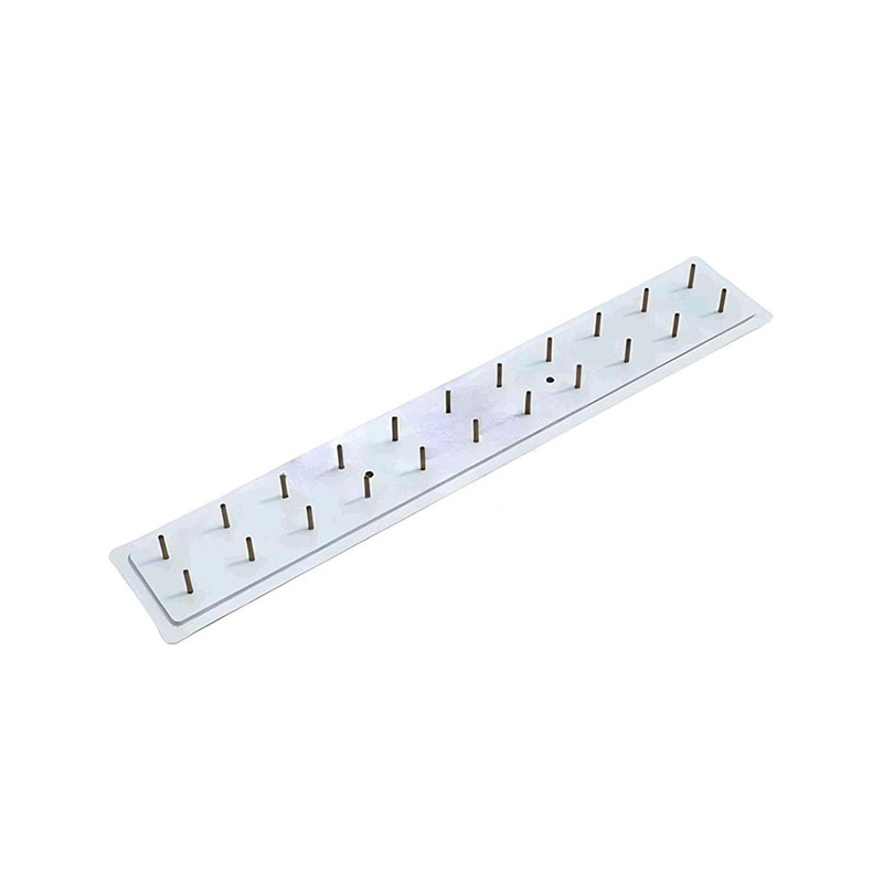
Network Communication Composite Laminated Busbar
Content
- 1. The Role of Busbars in Network Communication Equipment
- 2. Product Overview and Key Specifications
- 3. Composite Laminated Construction
- 4. Electrical Performance for High-Current DC Distribution
- 5. Low Inductance and Electromagnetic Compatibility
- 6. Insulation Safety and Partial Discharge Control
- 7. Thermal Performance and Heat Management
- 8. Installation Efficiency and Space Utilization
- 9. Advantages Compared with Conventional Cable Assemblies
- 10. Manufacturing Strengths and Process Control
- 11. Company Capabilities in Precision Energy Components
- 12. Application Areas
- 13. Custom OEM and ODM Support
- 14. Quality, Reliability, and Service Life
- 15. Installation and Design Recommendations
- 16. Sustainability and Manufacturing Efficiency
- 17. Why Choose a Specialized Manufacturer?
- 18. Procurement Considerations for Communication Equipment Manufacturers
- 19. Q&A
- Q1: What is a composite laminated busbar?
- Q2: What is the rated current of this network communication busbar?
- Q3: What is the operating voltage?
- Q4: Why is tin plating used on the copper busbar?
- Q5: How does the laminated structure help communication equipment?
- Q6: Can the busbar be customized?
- Q7: Is the product suitable for data centers?
- Q8: What manufacturing capabilities support this product?
- Q9: How should the busbar be installed?
- Q10: What tests can be performed on the finished product?
- Q11: What industries can use this type of busbar?
- Q12: Why use a busbar instead of multiple cables?
- 20. Conclusion
- References
- Product: Network Communication Composite Laminated Busbar
1. The Role of Busbars in Network Communication Equipment
Network communication systems are frequently associated with data transmission, switching performance, signal processing, and software control. However, none of these functions can operate reliably without a robust power distribution structure. Every server, router, switch, power conversion unit, storage system, and communication cabinet depends on a controlled electrical supply.
In small installations, individual wires and cable assemblies may be sufficient. As the power density of communication equipment increases, however, conventional wiring can become difficult to manage. Multiple cables require additional routing space, termination points, supports, and protective measures. They may also create inconsistent electrical paths, higher parasitic inductance, greater assembly time, and more complicated maintenance procedures.
A laminated busbar provides an alternative by integrating conductive layers and insulation into a compact, organized component. Instead of arranging many individual cables separately, a busbar creates a defined current path with controlled spacing and mechanical positioning. This approach is particularly valuable in communication equipment, where available space is limited and the coexistence of high-current power paths and sensitive electronic signals increases the need for electrical control.
For network communication applications, the busbar must do more than carry current. It must withstand operating temperature, maintain insulation integrity, support repeated production assembly, minimize the risk of connection errors, and remain mechanically stable during long service periods. A well-designed laminated busbar can contribute to a cleaner internal layout, improved thermal management, simplified installation, and more consistent system performance.
The Network Communication Composite Laminated Busbar is developed around these requirements. Its structure is intended to provide an efficient power transmission path while supporting the electrical, mechanical, and installation demands of high-speed communication infrastructure.
2. Product Overview and Key Specifications
The product is a composite laminated busbar designed for network communication equipment and related power distribution systems. It uses a copper conductive plate with a tin-plated surface and an engineered insulation structure. The composite design allows the busbar to combine high conductivity with controlled dielectric separation and a compact physical form.
| Parameter | Specification |
|---|---|
| Product type | Network Communication Composite Laminated Busbar |
| Product category | Composite Laminated Busbar |
| Overall dimensions | 500 mm × 80 mm |
| Copper plate thickness | 3.0 mm |
| Surface plating | Tin |
| Rated voltage | 12 VDC |
| Rated current | 300 A |
| Insulation withstand voltage | 3.5 kV DC for 60 seconds |
| Insulation test leakage current | Below 2 mA |
The stated specifications represent a practical configuration for high-current, low-voltage DC distribution. A 300 A current rating makes the busbar suitable for power assemblies that require substantial current capacity within a controlled and space-efficient structure. The 12 VDC operating level corresponds to common low-voltage power architectures used in communication equipment, control systems, auxiliary power assemblies, and related electronic infrastructure.
Tin plating on the copper surface offers several practical benefits. It helps protect the copper from oxidation, supports reliable contact performance, and provides a suitable interface for terminals, bolts, connectors, and other connection hardware. Surface treatment is especially important when the product must maintain stable contact resistance over an extended operating period.
The 3.5 kV DC insulation withstand test for 60 seconds is significantly higher than the product’s nominal operating voltage. This type of dielectric verification is used to evaluate the insulation system’s ability to resist electrical stress and to identify defects or weaknesses that could compromise safe operation. The specified leakage current limit further supports consistent insulation quality.
Although the product is supplied in a defined configuration, laminated busbars can generally be adapted to customer requirements, including length, width, conductive layer configuration, terminal geometry, mounting locations, insulation materials, plating requirements, and connection interfaces. The final design should always be confirmed according to system voltage, current, ambient conditions, thermal requirements, creepage and clearance distances, and installation standards.
3. Composite Laminated Construction
The principal feature of this product is its composite laminated construction. A laminated busbar normally consists of one or more conductive layers separated and protected by engineered insulation materials. The layers are assembled into a controlled structure so that electrical spacing, mechanical positioning, and connection locations remain consistent from unit to unit.
Compared with loose cable assemblies, a laminated construction can provide a more predictable current path. The conductors are positioned according to the design rather than being routed individually by installers. This can reduce unnecessary loops, avoid cable congestion, and help maintain a compact internal arrangement.
The composite structure also supports the management of parasitic electrical characteristics. In high-speed communication environments, power distribution components operate near sensitive signal circuits, processors, switching devices, and data interfaces. Uncontrolled current loops can contribute to electromagnetic noise and transient behavior. By arranging conductive layers and insulation in a deliberate geometry, the busbar can help reduce current-loop area and support lower inductance compared with conventional separated wiring layouts.
Composite insulation serves multiple functions. It separates conductive layers, protects against accidental contact, supports dielectric strength, and contributes to the mechanical stability of the assembly. It can also help maintain the designed spacing between conductors when the busbar is installed in a confined cabinet or equipment frame.
The performance of a laminated busbar depends on the complete system rather than on one material alone. Copper conductivity, plating quality, insulation thickness, bonding or fastening quality, dimensional accuracy, edge treatment, and terminal design all influence the finished product. This is why manufacturing process control is central to the reliability of the busbar.
3.1 Copper Conductive Layers
Copper is widely used in busbar manufacturing because of its high electrical conductivity, good thermal conductivity, ductility, and suitability for precision forming. In the present product configuration, the copper plate thickness is 3.0 mm. This provides a substantial conductive section for carrying the specified 300 A current while maintaining a form factor suitable for laminated assembly.
The copper layer must be manufactured with controlled thickness, flatness, width, and edge quality. Uneven surfaces or burrs can affect insulation assembly, connection stability, and local electric-field distribution. Precision preparation of the copper plate is therefore an important step before plating and lamination.
3.2 Tin-Plated Surface
The copper conductor is finished with a tin surface plating. Tin is commonly used in electrical connection systems because it provides a protective surface and can support reliable contact with compatible terminals and fasteners. It also helps reduce the direct exposure of copper to environmental conditions that may cause surface oxidation.
Plating quality must be controlled across the relevant contact surfaces. Important factors include surface cleanliness, plating coverage, adhesion, thickness consistency, and resistance to handling damage. A stable plated surface can contribute to consistent contact resistance and improved long-term connection performance.
3.3 Engineered Insulation
The insulation structure is selected to provide electrical separation, mechanical protection, and resistance to the thermal conditions expected in service. The material and thickness must be matched to the operating voltage, test voltage, clearance requirements, temperature rise, and assembly design.
For communication equipment, insulation must also be compatible with compact layouts. It should provide dependable separation without introducing unnecessary bulk. A balanced design allows the busbar to fit within limited cabinet space while maintaining the required dielectric performance.
4. Electrical Performance for High-Current DC Distribution
The product is rated for 12 VDC and 300 A. This combination reflects the requirements of power distribution systems in which a relatively low voltage is combined with a high current. At low voltage, even small amounts of resistance can produce meaningful voltage drop and heat generation. As a result, conductor geometry, contact resistance, surface treatment, and connection quality are critical.
A defined copper plate provides a stable and repeatable current path. Compared with a collection of individually routed conductors, the laminated busbar can simplify the electrical layout and reduce variation caused by differences in cable length, bending radius, terminal compression, and manual routing.
Current capacity is influenced by several factors, including conductor cross-section, ambient temperature, enclosure conditions, airflow, installation orientation, connection resistance, duty cycle, and permissible temperature rise. The 300 A rating should therefore be evaluated together with the customer’s actual thermal environment. For a complete system design, engineers should verify operating temperature, heat dissipation, current waveform, overload conditions, and the number of adjacent busbars or heat-producing components.
Low resistance is especially important in low-voltage systems. Excessive resistance may cause power loss, local heating, reduced voltage at the load, and accelerated degradation of contact interfaces. A precision-made busbar helps address these risks by providing controlled conductor dimensions and repeatable connection points.
The busbar’s tin-plated copper surface is also relevant to electrical stability. A clean and properly plated connection area can help maintain a dependable interface when assembled with suitable hardware. Correct tightening torque, appropriate washers or terminals, and protection against contamination remain necessary during installation.
5. Low Inductance and Electromagnetic Compatibility
Communication equipment combines high-speed digital signals with switching power converters and high-current DC distribution. This combination creates a demanding electromagnetic environment. Rapid current changes can generate voltage transients across parasitic inductance. If the power path is poorly arranged, these transients may contribute to conducted or radiated interference and can affect sensitive circuits.
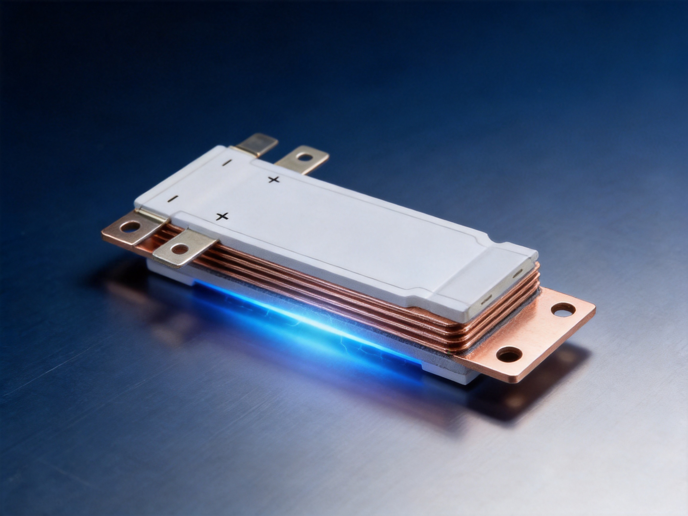
The laminated busbar’s controlled geometry is intended to support low-inductance power distribution. By keeping related conductive paths close together and reducing unnecessary loop area, the structure can help limit the inductive effects associated with changing current. This can be advantageous in systems containing switching converters, high-density processors, battery backup assemblies, and power semiconductor devices.
Lower inductance does not eliminate the need for system-level electromagnetic compatibility design. Equipment designers must still consider grounding, shielding, filtering, cable routing, switching frequency, transient suppression, enclosure design, and connector configuration. Nevertheless, the busbar provides a more controlled starting point than loosely arranged cable bundles.
Effective electromagnetic interference management is one of the key advantages of a composite laminated busbar over conventional point-to-point wiring. The busbar maintains a defined physical relationship between conductive layers and insulation. This repeatability can help equipment manufacturers achieve more consistent EMC performance across production units.
The busbar can also support cleaner internal architecture. When high-current paths are organized in a compact plane or layered structure, designers have more control over the separation between power circuits and signal circuits. This may simplify the development of communication cabinets and reduce the amount of trial-and-error associated with cable routing.
6. Insulation Safety and Partial Discharge Control
Electrical safety is a fundamental requirement for any power distribution component. Even a low-voltage operating system can experience transient conditions, maintenance-related exposure, contamination, or test voltages that place stress on insulation. The insulation system must therefore be carefully designed and verified.
The Network Communication Composite Laminated Busbar is specified with an insulation withstand voltage of 3.5 kV DC for 60 seconds and a leakage current below 2 mA. This test places controlled electrical stress on the insulation for a defined time. Passing the test helps demonstrate that the finished assembly has sufficient dielectric integrity for its intended application.
Insulation performance depends on more than the nominal material specification. Edges, corners, holes, interfaces, joints, voids, contamination, and inconsistent bonding can all create localized electrical stress. Precision manufacturing is therefore required to ensure that the insulation structure remains complete and properly aligned.
Partial discharge control is another important consideration in high-reliability electrical assemblies. Partial discharge refers to localized electrical activity within or across an insulation system that does not immediately bridge the entire insulation distance. Over time, repeated discharge can degrade materials and create a pathway toward failure.
A well-designed composite busbar can help control partial discharge by maintaining appropriate insulation thickness, avoiding sharp conductive edges, reducing voids, and controlling interfaces between materials. Manufacturing cleanliness and process consistency are also important. While final qualification requirements depend on the customer’s application and relevant standards, the design philosophy of controlling electric-field concentration supports long-term reliability.
Electrical testing should be performed using calibrated equipment and controlled procedures. Typical quality activities may include visual inspection, dimensional verification, continuity testing, insulation resistance testing, withstand voltage testing, plating inspection, and connection resistance evaluation. Additional tests may be applied for specific projects, such as thermal cycling, vibration, humidity exposure, or mechanical endurance.
7. Thermal Performance and Heat Management
High-current DC distribution inevitably generates some heat. The amount depends on conductor resistance, contact resistance, current level, duty cycle, ambient temperature, and heat dissipation conditions. In a compact communication cabinet, thermal management can be challenging because multiple power converters, processors, fans, and storage components may operate in a confined space.
The copper plate provides both electrical and thermal conductivity. Heat generated in the conductor or connection area can be distributed through the copper structure and transferred to the surrounding environment or adjacent thermal management components. The laminated construction also helps maintain a predictable physical layout, which supports more systematic airflow and thermal analysis.
Optimized heat resistance is not limited to the copper conductor. The insulation material, bonding interfaces, plating, fasteners, and surrounding enclosure must all remain stable within the expected operating temperature range. A properly selected composite structure should resist softening, cracking, delamination, or loss of dielectric performance under normal service conditions.
When integrating the busbar into equipment, engineers should calculate temperature rise at the rated current and under realistic airflow conditions. Special attention should be paid to terminal areas because connection resistance can create localized hot spots. Fasteners should be tightened according to the specified torque, and contact surfaces should be kept clean and correctly aligned.
The busbar design can also contribute to system-level thermal efficiency by eliminating unnecessary cable bundles. Cables can obstruct airflow or create irregular thermal zones within a cabinet. A compact laminated component may allow more direct airflow paths and easier placement of cooling components.
8. Installation Efficiency and Space Utilization
One of the most visible advantages of a laminated busbar is installation efficiency. Conventional cable assemblies often require cutting, stripping, crimping, labeling, routing, bundling, and inspection. Each additional cable introduces another opportunity for incorrect length, polarity reversal, insufficient crimping, loose fastening, or routing interference.
A pre-engineered busbar consolidates many of these operations into one manufactured component. Its dimensions, terminal locations, and insulation structure are defined before delivery. During equipment assembly, installers can position the busbar according to the approved mounting design and complete the specified connections.
This can lower installation cost in several ways. It reduces the number of separate parts, shortens assembly time, limits manual cable preparation, and simplifies inspection. It can also reduce the amount of auxiliary hardware needed for cable management, including clips, ties, supports, and protective sleeves.
Compact design is especially valuable in communication equipment. Cabinets and racks are often designed around strict dimensional limits, while power density continues to increase. A laminated busbar can use available space more efficiently than a large collection of cables routed through multiple directions.
Space efficiency may also improve maintenance access. A clearly defined busbar layout makes power paths easier to identify and can help technicians understand the equipment architecture. When service work is required, a structured component may be easier to inspect than a dense cable bundle.
Installation benefits depend on correct engineering documentation. The manufacturer can support customer projects by providing dimensional drawings, terminal definitions, material information, inspection requirements, and recommended installation procedures. For OEM programs, these documents help maintain consistency between the busbar and the customer’s equipment design.
9. Advantages Compared with Conventional Cable Assemblies
Conventional cables remain useful in many applications, particularly where flexibility, long-distance routing, or frequent movement is required. However, fixed high-current power distribution inside communication equipment often benefits from the more controlled structure of a laminated busbar.
| Design consideration | Conventional cable assembly | Composite laminated busbar |
|---|---|---|
| Current path | Dependent on multiple cables and terminations | Defined conductive plate geometry |
| Installation | Requires routing, crimping, bundling, and labeling | Pre-engineered component with controlled interfaces |
| Space usage | May require larger routing volume | Compact layered structure |
| Inductance control | Strongly affected by cable separation and loop area | Supported by controlled conductor arrangement |
| Connection consistency | Can vary with manual assembly | Repeatable manufactured terminal locations |
| Maintenance | Dense bundles may be difficult to trace | Structured power distribution layout |
| Customization | Flexible routing but many assembly variables | Custom geometry with production repeatability |
The laminated busbar’s main competitive advantage is integration. It combines current conduction, insulation, mechanical organization, and connection positioning in one component. This reduces the number of separate design variables that must be controlled during equipment assembly.
Compared with rigid, uninsulated busbars, a composite laminated structure provides greater protection against accidental contact and unintended short circuits. The insulation also allows conductors to be placed closer together when the electrical design permits, which supports compact equipment layouts.
Compared with simple flat copper strips, the laminated design offers improved system organization and better control of insulation interfaces. Compared with loose wires, it can provide more predictable inductive and thermal behavior. These advantages are particularly relevant to communication systems where electrical noise, limited space, and production consistency are important.
10. Manufacturing Strengths and Process Control
The performance of a laminated busbar depends heavily on the manufacturer’s ability to control each production stage. Zhejiang Zhongyan New Energy Co., Ltd. focuses on precision conductive components and has developed experience in power transmission and connection products for new energy, electrical equipment, communication, transportation, and energy storage applications.
The company brings together experienced engineers and technical teams covering product design, materials, process development, manufacturing, testing, and verification. This integrated capability allows the busbar to be treated as part of a complete electrical system rather than as an isolated metal component.
10.1 Engineering Design
The manufacturing process begins with understanding the customer’s electrical and mechanical requirements. Engineers evaluate operating voltage, current, dimensions, terminal configuration, insulation distances, mounting conditions, thermal environment, and production quantities.
For customized designs, the engineering team can develop the conductive geometry and insulation arrangement around the customer’s equipment. Important design features may include mounting holes, offset sections, connection pads, bends, clearances, protective covers, and interface locations.
Design verification should include current capacity, temperature rise, mechanical fit, insulation performance, manufacturability, and service accessibility. Early consideration of these factors can reduce redesign risk and help the final component integrate smoothly into the customer’s assembly line.
10.2 Copper Preparation and Forming
The copper plate must be cut and formed according to the approved drawings. Precision equipment helps maintain dimensional accuracy, edge quality, flatness, and repeatability. Depending on the design, forming may include punching, bending, shaping, drilling, or other controlled operations.
Edges must be inspected for burrs or sharp projections that could damage insulation or create concentrated electrical fields. Correct forming also helps ensure that the busbar sits securely against its mounting surfaces and that connection interfaces align with the equipment housing.
10.3 Surface Treatment
Before tin plating, the copper surface must be properly prepared. Cleaning and pretreatment remove contaminants and support plating adhesion. The plating process is controlled to achieve suitable coverage and a consistent finished surface.
Inspection may include visual evaluation, dimensional checks, adhesion assessment, and verification of relevant surface requirements. The objective is to create a durable interface that supports stable electrical connections and protects the copper during handling and service.
10.4 Insulation Lamination and Assembly
The conductive components and insulation materials are assembled according to a controlled process. Alignment is critical because an offset layer can affect clearance, connection positioning, and mechanical fit. Pressure, temperature, bonding conditions, and curing parameters may be controlled according to the selected insulation system.
Process control helps prevent voids, wrinkles, delamination, contamination, and insufficient bonding. The finished assembly should maintain the specified insulation coverage and remain stable during transportation, installation, and operation.
10.5 Testing and Verification
Testing confirms that the finished busbar meets the required electrical and dimensional specifications. The stated product configuration includes a 3.5 kV DC insulation withstand test for 60 seconds with leakage current below 2 mA.
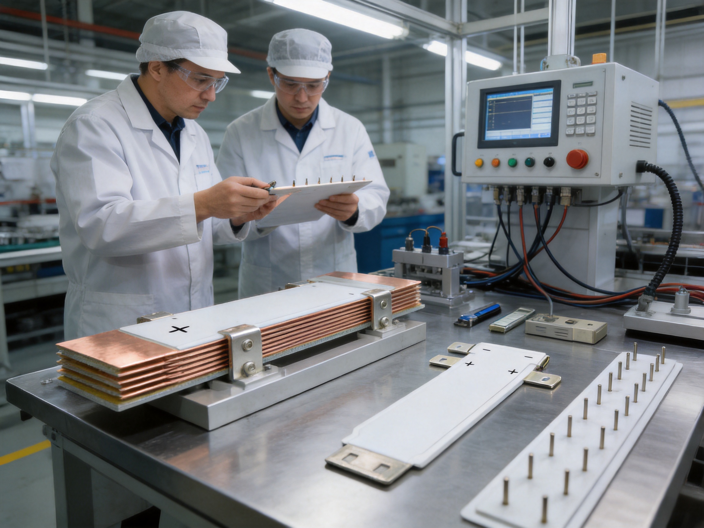
Additional checks may include conductor continuity, insulation resistance, dimensional inspection, surface inspection, plating evaluation, terminal alignment, and connection resistance. For qualification or customer-specific programs, environmental and mechanical tests can be introduced according to the application.
A documented quality system supports traceability from raw materials to finished products. Stable records help manufacturers identify process trends, manage nonconformities, and improve production consistency over time.
11. Company Capabilities in Precision Energy Components
Zhejiang Zhongyan New Energy Co., Ltd. is a high-tech enterprise specializing in new energy conductive components and precision electrical connection solutions. Its product scope includes high-voltage electrical copper foil soft connections, special-shaped soft connections, battery soft connections, and related conductive components.
The company was established in 2022 and has focused on precision components for battery and power systems. Its technical capabilities include polymer diffusion welding and laser technology, which are used to produce electrical connection products with low internal resistance and high reliability.
Experience in battery soft connections is valuable to composite busbar manufacturing because both product families require careful control of conductivity, contact quality, material interfaces, thermal behavior, and mechanical reliability. Battery applications also demand consistent production quality because a small connection defect can affect system performance and safety.
The company has supplied products to leading enterprises, including BYD, CATL, and Jaguar. Such customer experience indicates exposure to demanding requirements related to engineering approval, quality consistency, delivery management, and application reliability. Each customer project remains subject to its own technical specifications and qualification procedures.
The company is also developing an integrated research and development system covering materials science, precision machining, testing, and verification. This broad approach supports the development of customized conductive components for power distribution, electric vehicles, rail transit, communication equipment, and energy storage systems.
Its long-term development includes the expansion of lithium battery manufacturing and the integrated design of battery cells and connection systems. This direction creates opportunities for closer coordination between energy storage components, cell interfaces, busbars, insulation systems, and complete battery assemblies.
12. Application Areas
12.1 Data Centers
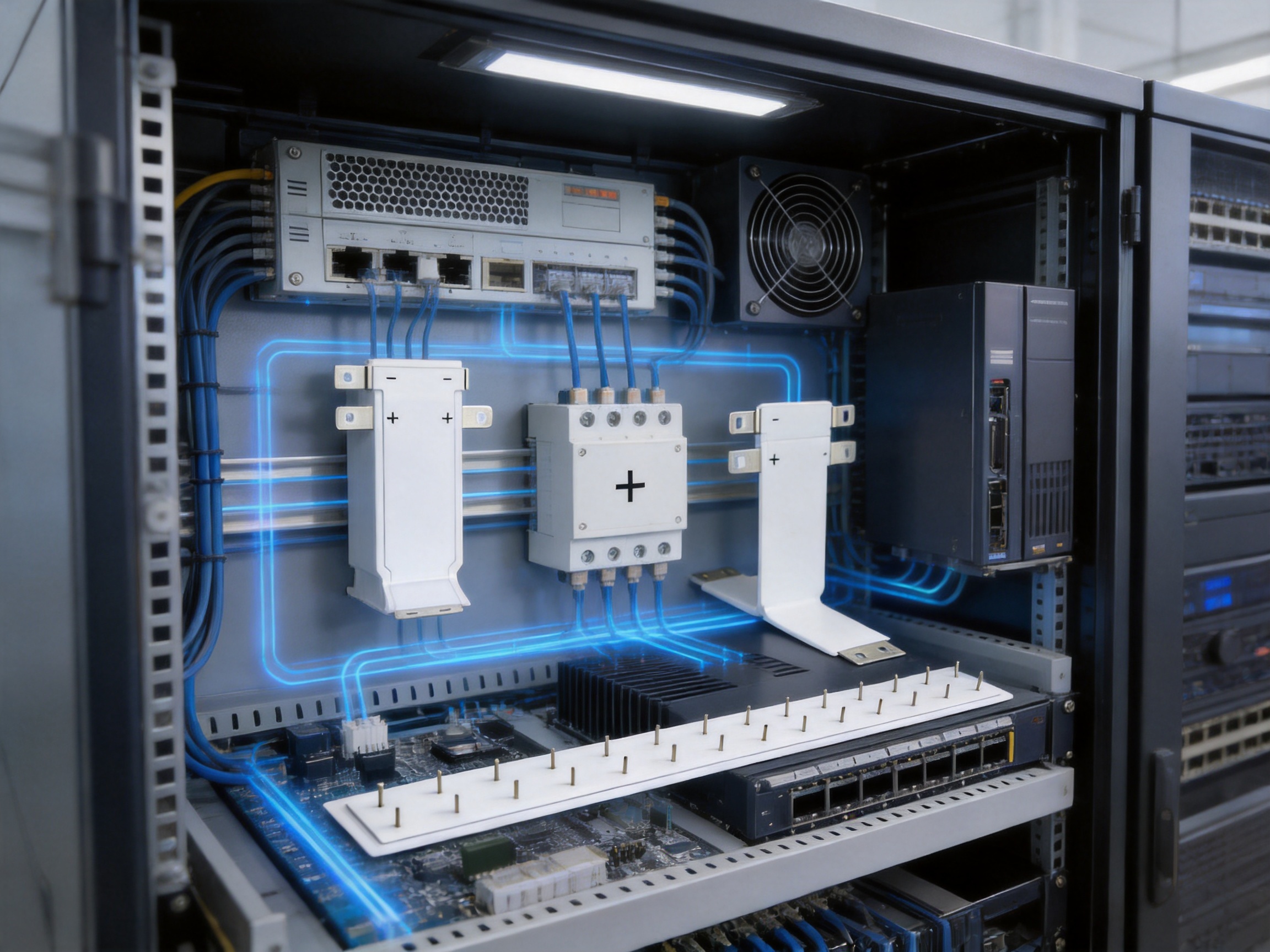
Data centers require high availability, efficient power distribution, compact rack architecture, and serviceable internal layouts. The busbar can be used in low-voltage DC distribution sections, power conversion assemblies, server power interfaces, and auxiliary power systems where high current must be delivered within a controlled space.
Its low-inductance structure can be beneficial in systems with rapidly switching power electronics. The compact format may also simplify rack design and reduce the cable congestion that often occurs in high-density power zones.
12.2 Telecommunications Equipment
Telecommunications cabinets, base-station power systems, network aggregation equipment, and transmission platforms require reliable power connections that can operate continuously. The busbar can support organized power distribution between rectifiers, backup systems, control units, and communication modules.
The insulated laminated structure helps protect conductive paths from accidental contact while supporting repeatable production and installation. Tin-plated interfaces can be matched with suitable terminals and connection hardware for long-term service.
12.3 Network Switches and Routers
High-capacity switches and routers combine dense electronic functions with demanding power requirements. Internal space is valuable, and electrical noise must be controlled so that power distribution does not interfere with signal processing.
A customized laminated busbar can be designed around the equipment’s mechanical envelope, mounting locations, and power entry points. This may reduce wiring complexity and provide a cleaner relationship between the power system and signal processing areas.
12.4 Edge Computing Systems
Edge computing installations are often deployed in compact cabinets or locations with limited service access. They require robust, space-efficient power components that can tolerate variable ambient conditions and support modular equipment arrangements.
The busbar’s compact structure and defined connection layout can help simplify assembly and maintenance in edge infrastructure. The final design should be selected according to the environmental and thermal conditions of the installation site.
12.5 Energy Storage and Backup Power
Communication systems frequently use batteries or energy storage units for backup power. The same manufacturing expertise used for battery soft connections and conductive components can support busbar applications within energy storage cabinets, backup power systems, and DC distribution modules.
In these systems, low resistance, connection reliability, insulation integrity, and thermal control are particularly important. Customized busbars may be developed to connect battery modules, protection systems, power conversion units, and distribution terminals.
13. Custom OEM and ODM Support
Communication equipment manufacturers often require components that match their own cabinet architecture, electrical interfaces, and assembly processes. Standard products may not provide the correct terminal locations, mounting pattern, insulation shape, or current path. Custom OEM and ODM support is therefore an important part of busbar supply.
A customized project normally begins with customer drawings, three-dimensional models, electrical specifications, or physical samples. The manufacturer reviews the design for material compatibility, manufacturability, insulation requirements, forming limitations, and testing needs.
Customization may include overall length and width, copper thickness, number of conductive layers, terminal geometry, hole pattern, bending profile, insulation color, protective structure, surface plating, labeling, and packaging. The design can also be adjusted for specific connectors, studs, power modules, fuse holders, circuit breakers, or battery terminals.
Engineering collaboration is important because a change in one feature may influence other performance characteristics. For example, reducing the distance between conductors may affect insulation requirements, while increasing current capacity may influence thermal design and copper thickness. A professional supplier helps the customer balance electrical performance, mechanical fit, cost, and production efficiency.
After prototype approval, the production process can be transferred to controlled mass manufacturing. First-article inspection, sample approval, process validation, and ongoing quality checks help ensure that production units remain consistent with the approved design.
14. Quality, Reliability, and Service Life
Reliability in communication infrastructure is measured over long operating periods. Equipment may operate continuously, with limited opportunities for maintenance. A busbar must therefore maintain conductivity, insulation performance, mechanical stability, and connection integrity throughout its intended service life.
The product’s long-service-life advantage is supported by several design elements: a robust copper conductor, a protective tin-plated surface, composite insulation, controlled manufacturing, and electrical testing. These features work together to reduce common risks such as oxidation, loose connections, insulation breakdown, excessive voltage drop, and localized overheating.
Durability also depends on how the busbar is installed. Improper bending, excessive mechanical force, incorrect torque, contamination, unsupported weight, or exposure beyond the specified environmental range can reduce service life. Customers should follow the manufacturer’s installation instructions and confirm the design under actual operating conditions.
For production customers, consistent quality is as important as individual product performance. Variation in dimensions or connection points can create assembly delays and field reliability concerns. A manufacturer with controlled processes, documented inspection, and engineering support can help reduce this variation.
Reliability verification may be expanded according to the application. Possible qualification activities include thermal cycling, high-temperature storage, humidity exposure, vibration, mechanical shock, insulation aging, current-carrying temperature-rise testing, and repeated connection testing. The appropriate program should be agreed upon between the manufacturer and customer.
15. Installation and Design Recommendations
Before installation, confirm that the busbar dimensions, current rating, voltage level, terminal locations, and insulation requirements match the equipment design. Inspect the product for visible damage, contamination, deformation, or signs of packaging-related stress.
Connection surfaces should be clean and correctly aligned. Fasteners should be selected according to the busbar design and tightened to the recommended torque. Excessive torque can deform the conductor or damage the interface, while insufficient torque can increase contact resistance and create heat.
The busbar should be supported at the intended mounting points. Unsupported sections may experience vibration or mechanical stress, particularly during transportation or in equipment subject to fan vibration and thermal expansion.
Clearance and creepage distances should be maintained according to the system voltage and applicable design standards. Additional components, mounting hardware, cable shields, and metal frames should not compromise the insulation structure or create unintended contact paths.
Thermal design should consider nearby heat sources, airflow direction, enclosure temperature, and continuous current. If the busbar operates near its current limit, the customer should verify temperature rise under the actual operating profile rather than relying only on nominal calculations.
After installation, electrical checks should be performed according to the equipment’s quality procedure. These may include continuity, polarity, insulation resistance, withstand voltage, connection torque verification, and visual inspection. Any test voltage applied to the finished equipment should be compatible with the busbar’s insulation system and the requirements of other connected components.
16. Sustainability and Manufacturing Efficiency
Efficient material use and reduced assembly complexity are increasingly important in electrical equipment manufacturing. A laminated busbar can reduce the need for multiple cable lengths, terminal accessories, cable supports, and protective materials. This may lower material consumption and simplify production logistics.
Its compact structure can also contribute to smaller equipment layouts. Reduced cabinet volume may lower transportation requirements and support more efficient use of installation space. The actual environmental benefit depends on the complete product design, manufacturing process, operating efficiency, and end-of-life treatment.
Manufacturing efficiency is improved when a component integrates multiple functions. The busbar combines current conduction, insulation, positioning, and connection organization. This reduces the number of separate operations required during final equipment assembly and can support a more repeatable production workflow.
The company’s focus on new energy conductive components aligns with broader demand for efficient power transmission, energy storage, electric transportation, and low-carbon infrastructure. Its continued investment in materials, precision manufacturing, testing, and battery-related technologies supports the development of products for a more electrified industrial environment.
17. Why Choose a Specialized Manufacturer?
A specialized manufacturer understands that a busbar is not simply a shaped piece of copper. The finished component must satisfy electrical, thermal, mechanical, insulation, manufacturing, and installation requirements at the same time.
Specialized engineering experience helps identify problems before production begins. These may include insufficient clearance, difficult terminal access, excessive bending stress, poor heat dissipation, incompatible plating, weak insulation interfaces, or assembly steps that are difficult to automate.
A manufacturer with experience across communication, energy storage, electric vehicles, rail transit, and power distribution can apply knowledge from different industries. For example, battery connection products emphasize low resistance and repeatability, while communication systems emphasize compact design and electromagnetic control. Combining these perspectives can support more capable busbar development.
Integrated manufacturing also improves communication between engineering and production teams. Design changes can be evaluated according to actual process capabilities, available equipment, inspection methods, and production economics. This helps customers move from prototype to mass production with fewer unexpected obstacles.
Zhejiang Zhongyan New Energy Co., Ltd. provides this combination of product development, precision manufacturing, testing, and application support. Its focus on customized conductive components makes it suitable for customers seeking more than a standard catalog part.
18. Procurement Considerations for Communication Equipment Manufacturers
When selecting a composite laminated busbar supplier, buyers should evaluate more than the quoted unit price. The total value includes engineering support, tooling requirements, production consistency, inspection capability, packaging, delivery reliability, and long-term technical cooperation.
Electrical requirements should be clearly defined. These include nominal voltage, maximum continuous current, overload current, transient conditions, allowable temperature rise, insulation withstand voltage, leakage current, and applicable safety standards.
Mechanical requirements should include overall dimensions, mounting points, terminal positions, bending tolerances, connector interfaces, allowable weight, vibration conditions, and cabinet installation procedures. Three-dimensional drawings can be useful for checking interference and service access.
Material and surface requirements should specify copper grade, conductor thickness, insulation material, plating type, plating coverage, color or marking requirements, and any restrictions on hazardous substances or environmental compliance.
Quality requirements should identify inspection points, sampling plans, test methods, certificates, traceability expectations, packaging conditions, and procedures for handling nonconforming products. For critical equipment, customers may request process audits, first-article approval, and regular production reports.
A strong supplier should be able to discuss these requirements in engineering terms and translate them into a controlled manufacturing plan. This reduces the risk that an apparently low-cost product will create higher expenses during assembly, testing, or field service.
19. Q&A
Q1: What is a composite laminated busbar?
A composite laminated busbar is an electrical distribution component that combines conductive metal layers with engineered insulation in a controlled, compact structure. It provides current conduction, insulation, mechanical organization, and defined connection interfaces in one assembly.
Q2: What is the rated current of this network communication busbar?
The specified rated current is 300 A. Actual allowable current should be confirmed according to ambient temperature, airflow, duty cycle, connection conditions, enclosure design, and permissible temperature rise.
Q3: What is the operating voltage?
The listed operating voltage is 12 VDC. The product also has an insulation withstand specification of 3.5 kV DC for 60 seconds with leakage current below 2 mA. Operating voltage and test voltage are different parameters and should not be confused.
Q4: Why is tin plating used on the copper busbar?
Tin plating helps protect the copper surface from oxidation and provides a suitable contact interface for compatible terminals and connection hardware. It can also support stable electrical contact performance when the connection is correctly designed and installed.
Q5: How does the laminated structure help communication equipment?
The laminated structure provides a compact and organized current path, reduces cable congestion, supports low-inductance design, and helps separate conductive layers. These characteristics can assist with electromagnetic interference management, thermal organization, installation efficiency, and equipment space utilization.
Q6: Can the busbar be customized?
Yes. Customization may include dimensions, copper thickness, terminal shape, mounting holes, bending geometry, insulation arrangement, plating requirements, connection interfaces, and packaging. The final design should be developed from the customer’s electrical and mechanical requirements.
Q7: Is the product suitable for data centers?
It can be considered for suitable low-voltage, high-current DC distribution applications within data centers. Engineers should verify current capacity, temperature rise, insulation, enclosure conditions, mounting, and compliance requirements before approval.
Q8: What manufacturing capabilities support this product?
The manufacturer has capabilities in conductive component design, copper processing, surface treatment, composite assembly, precision manufacturing, electrical testing, and customized product development. Its experience also includes battery soft connections and other new energy electrical components.
Q9: How should the busbar be installed?
The busbar should be installed according to approved drawings and instructions. Connection surfaces must be clean, fasteners must use suitable torque, the component must be supported at the intended points, and required clearance, creepage, polarity, and insulation checks must be maintained.
Q10: What tests can be performed on the finished product?
Typical tests may include dimensional inspection, visual inspection, continuity, insulation resistance, withstand voltage, leakage current, plating evaluation, terminal alignment, and connection resistance. Additional thermal, vibration, humidity, and aging tests may be specified for particular applications.
Q11: What industries can use this type of busbar?
Potential industries include telecommunications, data centers, networking equipment, edge computing, power electronics, energy storage, electric vehicles, rail transit, industrial control, and renewable energy systems.
Q12: Why use a busbar instead of multiple cables?
A busbar can reduce installation complexity, improve space utilization, provide a more controlled current path, support lower-inductance design, reduce connection variation, and simplify maintenance. Cables may still be preferable where flexibility or long-distance routing is required.
20. Conclusion
The Network Communication Composite Laminated Busbar is designed for the demanding power distribution requirements of high-speed communication equipment. Its 500 mm × 80 mm structure, 3.0 mm copper plate, tin-plated surface, 12 VDC rating, and 300 A current capacity provide a practical platform for compact, high-current DC systems.
Its most important value comes from the combination of functions. The product is not only a conductor. It also provides insulation, mechanical organization, controlled connection points, low-inductance potential, and installation efficiency. These characteristics can help communication equipment manufacturers address limited space, electromagnetic interference, thermal management, production consistency, and serviceability.
The company’s strengths in precision conductive components, battery connections, polymer diffusion welding, laser technology, engineering development, and testing provide a strong foundation for manufacturing customized busbar solutions. Its experience across new energy, electric vehicles, rail transit, communication, and energy storage applications supports the development of reliable products for complex electrical systems.
For equipment manufacturers seeking a stable alternative to complicated cable assemblies or uninsulated rigid conductors, a composite laminated busbar can provide a more integrated and repeatable approach. With appropriate engineering review, thermal verification, insulation testing, and installation control, the product can support dependable power distribution in data centers, telecommunications equipment, network platforms, and other high-density electrical applications.
References
1. IEC 60439 Series, Low-Voltage Switchgear and Controlgear Assemblies, technical principles for low-voltage power distribution equipment.
2. IEC 60664 Series, Insulation Coordination for Equipment within Low-Voltage Systems.
3. IEC 60216 Series, Electrical Insulating Materials and Thermal Endurance Properties.
4. IEC 60512 Series, Connectors for Electronic Equipment and Electrical Testing Methods.
5. IEEE EMC Engineering Guidelines, principles of electromagnetic compatibility in electronic and communication equipment.
6. Copper Development Association, technical information concerning copper conductivity, thermal performance, and electrical applications.
7. General engineering practices for laminated busbar design, insulation coordination, current-carrying capacity, and thermal management.
8. Manufacturer-provided product specifications for the Network Communication Composite Laminated Busbar.
Product: Network Communication Composite Laminated Busbar

Driven by the development of new energy and aiming for "zero carbon".
Copyright © Zhejiang Zhongyan New Energy Co., Ltd. All Rights Reserved.
