 English
 Español

Eco-Friendly Composite Laminated Busbars for Sustainable Power Systems
As electrical systems become more compact, more intelligent, and more closely connected to renewable energy, the demand for reliable power distribution components continues to grow. Busbars are central to this development because they carry and distribute electrical current while supporting the safety, efficiency, serviceability, and overall architecture of modern equipment. In applications such as solar power conversion, wind energy, energy storage, electric vehicle charging, smart grids, and low-carbon industrial equipment, the busbar is no longer viewed as a simple metal conductor. It is an engineered electrical assembly that must manage current, heat, insulation, electromagnetic behavior, mechanical constraints, and long-term operating reliability.
The Eco-Friendly Composite Laminated Busbar is designed for this demanding environment. It combines conductive copper plates, engineered insulation, laminated construction, and precision manufacturing into a compact power distribution component. Its purpose is not merely to connect electrical points. It is designed to reduce stray inductance, improve connection accuracy, simplify installation, support electromagnetic compatibility, and help equipment manufacturers achieve more sustainable product designs.
With recyclable material options, a low-loss electrical design, and an eco-conscious manufacturing philosophy, this composite laminated busbar provides a practical solution for organizations seeking to improve both electrical performance and environmental responsibility. It is suitable for renewable energy systems, battery energy storage systems, electric vehicle charging equipment, industrial power conversion, microgrids, commercial buildings, and environmental protection equipment.
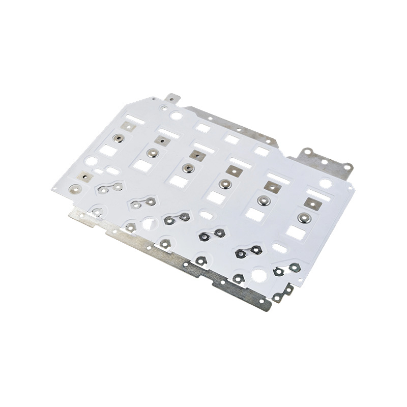
Eco-Friendly Composite Laminated Busbar
1. The Role of Laminated Busbars in Modern Electrical Equipment
Traditional cable-based power distribution can be effective in many installations, but it often requires multiple cables, separate insulation layers, additional supports, and a larger installation area. As current levels rise and equipment becomes more compact, cable systems may create challenges related to routing, bend radius, heat accumulation, assembly time, and connection consistency.
A laminated busbar addresses these challenges by integrating multiple conductive layers and insulation into a structured, compact assembly. The positive and negative conductors, or multiple phase conductors where required, can be positioned in a controlled geometric relationship. This arrangement shortens current paths and reduces the loop area through which magnetic fields develop. The resulting electrical configuration can help lower parasitic inductance and improve the dynamic behavior of power conversion equipment.
In high-frequency switching applications, the physical layout of conductors is especially important. Fast switching devices can generate voltage transients and electromagnetic disturbances when current changes rapidly. A carefully designed laminated busbar helps control the electrical path between power devices, capacitors, converters, and loads. By reducing unnecessary conductor length and maintaining consistent spacing, the busbar supports more predictable system behavior.
The laminated structure also contributes to mechanical organization. Instead of installing individual cables and insulating parts separately, equipment manufacturers can use a pre-engineered busbar assembly. This can reduce the number of loose components inside a cabinet or enclosure and make the final system easier to inspect, maintain, and reproduce during serial production.
2. Product Overview
The Eco-Friendly Composite Laminated Busbar is a customized power distribution component manufactured for applications that require reliable conductivity, electrical insulation, low inductance, thermal endurance, and efficient assembly. Its composite construction combines copper conductors with insulating materials selected for electrical and mechanical service conditions.
The product is configured with copper plates that have a tin-plated surface. Tin plating can support contact reliability, surface protection, and compatibility with a variety of connection methods. The copper plate thickness in the referenced configuration is 2.0 mm, while the overall component dimensions are approximately 350 mm × 300 mm.
The specified electrical performance includes a rated voltage of 540 VDC and a rated current of 200 A. The insulation withstand voltage is 3.5 kVDC for 60 seconds, with leakage below 2 mA under the stated test condition. These values make the product suitable for many low- and medium-voltage DC power distribution assemblies, subject to system-level validation, operating temperature, creepage and clearance requirements, and the final application design.
| Performance Item | Referenced Specification | Engineering Significance |
|---|---|---|
| Product type | Composite laminated busbar | Integrated conductive and insulating power distribution assembly |
| Approximate dimensions | 350 mm × 300 mm | Suitable for compact equipment layouts and customized enclosures |
| Copper plate thickness | 2.0 mm | Supports current carrying capability and mechanical stability |
| Surface treatment | Tin-plated copper surface | Improves surface protection and supports reliable electrical interfaces |
| Voltage rating | 540 VDC | Applicable to selected DC distribution and power conversion systems |
| Current rating | 200 A | Designed for substantial power transfer in industrial and new energy equipment |
| Insulation withstand voltage | 3.5 kVDC for 60 seconds | Supports dielectric verification during product qualification |
| Insulation leakage condition | Below 2 mA under the stated test | Indicates controlled insulation performance during withstand testing |
These specifications describe a representative product configuration rather than a limitation on customization. Busbars can be developed according to the required voltage, current, terminal pattern, insulation system, mounting structure, thermal environment, and equipment envelope. Engineering confirmation is necessary for every new project because electrical ratings depend on conductor thickness, material, temperature rise, joint design, ventilation, installation orientation, and duty cycle.
3. Eco-Friendly Design Philosophy
The environmental value of a busbar should be considered throughout its life cycle. Material selection, production efficiency, energy losses during operation, service life, repairability, and end-of-life handling all influence the sustainability of an electrical component. The Eco-Friendly Composite Laminated Busbar is developed around these factors rather than focusing only on initial manufacturing cost.
One important feature is the use of recyclable material options. Copper is a valuable and widely recyclable conductive material, and an engineered composite structure can be designed to minimize unnecessary material use while preserving electrical and mechanical performance. When the product is integrated into a well-designed system, compact construction may also reduce the amount of auxiliary insulation, support hardware, and cable management material required.
Low-loss design is another important element. Electrical losses create heat, increase energy consumption, and may reduce the efficiency of the equipment in which the busbar is installed. A carefully designed conductor geometry can help shorten current paths and reduce resistance-related losses. Consistent contact surfaces and properly designed connection points also help prevent localized heating caused by poor joints or uneven pressure.
Long service life contributes directly to sustainability. A component that maintains stable electrical and mechanical performance for many years reduces the need for replacement, avoids production of unnecessary spare parts, and limits downtime-related waste. The busbar’s robust composite construction, controlled insulation, and protective surface treatment are intended to support durable operation when properly designed and installed.
Eco-conscious manufacturing also means reducing avoidable production waste. Precision cutting, forming, insulation preparation, lamination, and inspection can help improve material utilization and reduce the number of rejected components. Consistent process control is particularly important for customized busbars because each product may contain a different geometry, terminal pattern, or insulating configuration.
4. Electrical Advantages Over Conventional Cable Assemblies
4.1 Lower Inductance
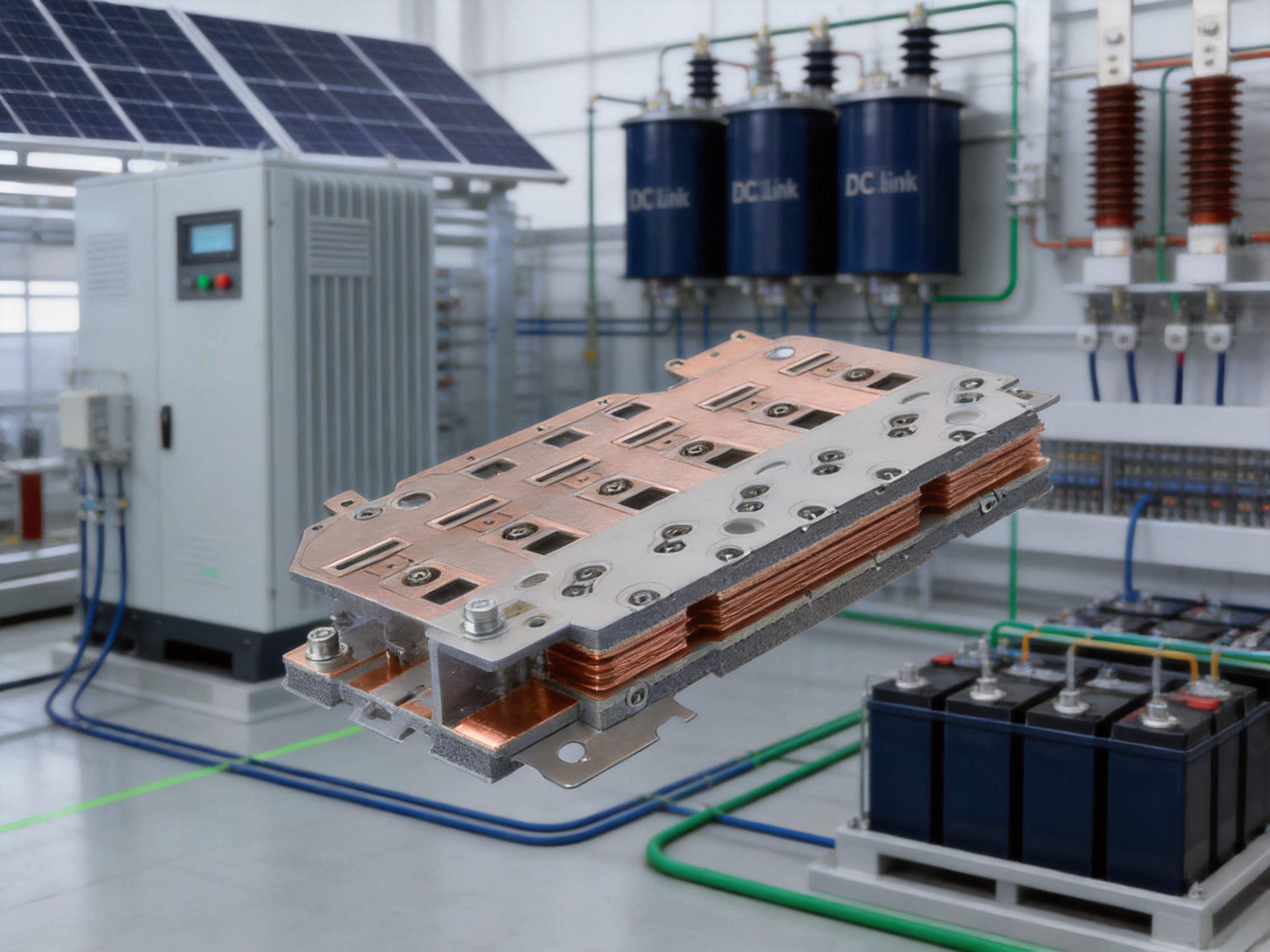
One of the principal advantages of laminated busbar construction is the ability to control conductor spacing and current path geometry. When conductors carrying opposing currents are placed close to one another, the magnetic fields can partially cancel. This reduces loop inductance compared with long, widely separated cable routes.
Lower inductance can be valuable in inverter systems, switching power supplies, battery energy storage converters, and electric vehicle charging equipment. During rapid switching, inductance can contribute to voltage overshoot and ringing. A lower-inductance interconnection may help reduce these effects and support the stable operation of power semiconductor devices. It can also reduce the burden on snubber circuits and other protective measures, although the complete system must still be evaluated through simulation and testing.
4.2 Improved Thermal Organization
A laminated busbar provides a defined arrangement of conductive layers instead of relying on several cables bundled into an enclosure. This allows engineers to analyze conductor spacing, heat transfer paths, mounting points, and the relationship between the busbar and nearby cooling structures.
The product is designed with optimized heat resistance for the intended operating environment. Proper thermal performance depends on copper cross-sectional area, current waveform, ambient temperature, airflow, enclosure design, terminal resistance, and duty cycle. The structured busbar design makes these factors easier to model and control during the engineering stage.
4.3 More Predictable Electromagnetic Behavior
Uncontrolled cable routing can increase electromagnetic radiation and susceptibility, particularly when high-current conductors are positioned close to sensitive control circuits. The compact and ordered geometry of a laminated busbar can reduce exposed loop area and support improved electromagnetic compatibility.
The product also incorporates enhanced electromagnetic interference shielding considerations within its composite design. This does not eliminate the need for system-level shielding, grounding, filtering, or enclosure design, but it provides a stronger foundation for controlling electromagnetic effects inside power equipment.
4.4 Reduced Assembly Complexity
Conventional cable assemblies may require separate crimping, routing, fastening, labeling, insulating, and inspection operations. A laminated busbar can combine several of these functions into one engineered component. This may reduce assembly time and decrease the risk of incorrect cable routing, reversed polarity, loose fasteners, or inadequate insulation separation.
For manufacturers producing large quantities of power conversion or energy storage equipment, repeatability is especially important. A pre-engineered busbar can be installed using a standardized procedure, helping improve production consistency and simplify worker training.
5. Safety and Reliability Features
Safety is a core requirement for any component used in high-current power distribution. A busbar must maintain electrical separation, withstand operating voltage, manage temperature, resist mechanical stress, and preserve connection integrity throughout its service life.
5.1 Partial Discharge Control
Partial discharge is a localized electrical discharge that can occur within insulation systems or at interfaces where electric field concentration is high. Over time, repeated partial discharge can degrade insulation and reduce the reliability of high-voltage equipment.
The composite laminated busbar is designed with effective partial discharge control in mind. This includes attention to insulation thickness, interface quality, edge treatment, conductor alignment, void reduction, and electric field distribution. The exact partial discharge performance must be verified according to the requirements of the specific application, but the laminated structure provides a controlled platform for insulation engineering.
5.2 Dielectric Strength
The referenced configuration has an insulation withstand voltage of 3.5 kVDC for 60 seconds with leakage below 2 mA. This type of dielectric test is used to evaluate whether the insulation can tolerate a specified electrical stress without breakdown or excessive leakage.
Withstand voltage testing is only one part of a complete qualification program. Depending on the application, additional tests may include insulation resistance, partial discharge, thermal cycling, humidity exposure, vibration, mechanical shock, salt spray, corrosion resistance, and long-duration current-carrying tests. The product can be incorporated into such validation programs according to customer and industry requirements.
5.3 Mechanical Stability
Busbars installed in industrial systems may experience vibration, thermal expansion, transportation shock, and repeated assembly operations. A composite laminated structure helps hold the conductors and insulation in a defined relationship, reducing the movement associated with loose cables.
Mechanical stability also depends on terminal design and mounting points. Properly distributed fasteners, controlled clamping force, suitable hole tolerances, and adequate support around connection areas can help prevent stress concentration. These details are addressed during customized design and production.
5.4 Connection Integrity
Electrical connections are common sources of field failure. Excessive contact resistance can generate heat, while insufficient tightening or misalignment can lead to vibration-related degradation. A precision-manufactured busbar can incorporate accurate terminal locations, defined connection surfaces, and controlled plating conditions.
By reducing the number of separate connections, the laminated design can also lower the total number of potential failure points. This advantage is particularly meaningful in compact energy storage systems, where access for maintenance may be limited.
6. Advanced Manufacturing Process
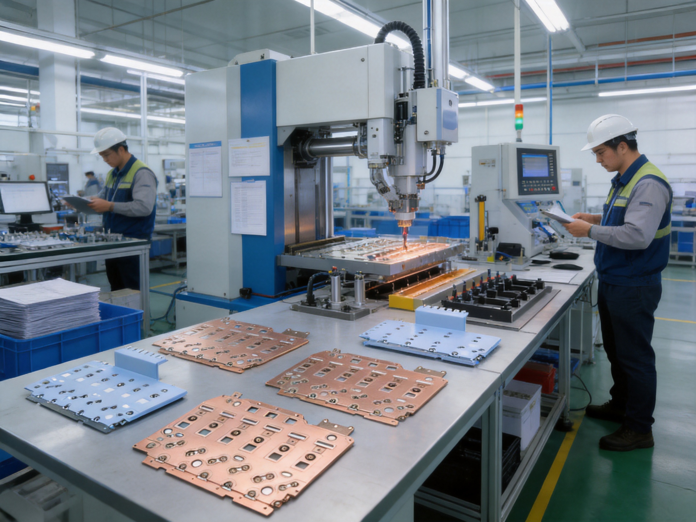
The performance of a composite laminated busbar depends not only on its material specification but also on the quality of its manufacturing process. Dimensional accuracy, surface condition, insulation placement, bonding consistency, and electrical testing all influence the final product. A professional manufacturer therefore treats the busbar as a precision engineered assembly rather than a basic piece of cut metal.
6.1 Engineering Review and Design Conversion
Production begins with a review of the customer’s electrical schematic, mechanical drawing, terminal requirements, insulation class, and installation environment. Engineers evaluate current paths, conductor thickness, terminal spacing, creepage and clearance, mounting points, bend or forming requirements, and access for installation.
The design is then converted into manufacturing data. This may include two-dimensional drawings, three-dimensional models, cutting files, bending instructions, inspection points, and assembly work instructions. Design review at this stage helps identify interference with capacitors, heat sinks, housings, cooling channels, fasteners, and other internal parts before prototypes are produced.
6.2 Copper Material Preparation
High-quality copper plate or copper sheet is selected according to conductivity, thickness, mechanical requirements, and the application’s thermal performance. Material traceability is important because it allows production teams to connect finished products with incoming material records and inspection results.
The copper is cut into the required profile using precision equipment. Accurate cutting helps maintain terminal dimensions, edge clearances, hole locations, and the fit between layers. Burr control is particularly important because sharp metal edges can damage insulation or create localized electric field concentration.
6.3 Precision Forming and Machining
Depending on the design, the copper conductors may require punching, drilling, bending, embossing, or other forming operations. These processes create mounting holes, connection terminals, offsets, steps, and three-dimensional profiles needed to fit the busbar inside the final equipment.
Precision forming reduces the need for manual adjustment during customer assembly. It also helps preserve consistent spacing between conductive layers. Production fixtures and inspection gauges can be used to verify critical dimensions and ensure that repeated batches remain within agreed tolerances.
6.4 Surface Treatment and Tin Plating
The referenced busbar configuration uses a tin-plated copper surface. Before plating, the copper surface must be properly cleaned and prepared to support uniform adhesion. Surface treatment can improve resistance to oxidation and provide a stable interface for electrical connections.
Plating thickness, coverage, appearance, and adhesion are controlled according to the product specification. Special attention is given to terminal areas, contact faces, and edges. A stable surface treatment helps support consistent contact resistance and improves the product’s suitability for long-term use in industrial environments.
6.5 Insulation Material Preparation
The insulating layers are prepared according to the electrical, thermal, and mechanical requirements of the design. Material selection considers dielectric strength, temperature resistance, flexibility, dimensional stability, flame behavior, and compatibility with the lamination process.
Insulating components are cut or formed to match the copper geometry. Openings for terminals and mounting points are produced with controlled tolerances. The insulation must cover the required conductive areas while maintaining necessary creepage and clearance distances.
6.6 Layer Alignment and Lamination
During assembly, copper conductors and insulating layers are positioned in a controlled sequence. Alignment is critical because even small shifts may affect terminal fit, insulation coverage, or conductor spacing. Dedicated fixtures can help maintain accurate layer registration during the lamination process.
Lamination joins the layers into a stable composite structure. The process parameters may include temperature, pressure, time, and material-specific curing conditions. Proper control helps reduce voids, delamination risk, uneven thickness, and internal stress.
Advanced process management is especially valuable for complex busbars with multiple layers, irregular outlines, stepped profiles, or integrated mounting features. A controlled lamination process supports repeatable mechanical strength and consistent electrical insulation.
6.7 Edge Finishing and Final Assembly
After lamination, exposed edges and connection areas are inspected and finished. Any burrs, excess insulation, contamination, or sharp transitions that could affect safety are removed or corrected. Additional components such as protective covers, insulating barriers, labels, or mounting hardware may be installed according to the customer’s requirements.
Final assembly is performed in accordance with documented work instructions. This helps ensure that product orientation, terminal identification, protective films, and packaging conditions remain consistent.
6.8 Electrical and Dimensional Testing
Testing is performed to confirm that the finished busbar meets the agreed technical requirements. Typical inspection items include conductor dimensions, hole position, flatness, terminal geometry, insulation coverage, surface treatment, appearance, and overall assembly dimensions.
Electrical tests may include continuity, contact resistance, insulation resistance, and dielectric withstand testing. For applications with high switching speed or elevated voltage stress, additional validation may include partial discharge measurement, temperature-rise testing, and electromagnetic performance analysis.
A mature production system combines automated or semi-automated equipment with skilled technical inspection. Automation improves repeatability, while experienced engineers remain essential for process development, nonconforming product analysis, and customized project support.
7. Manufacturing Strengths and Technical Capability
The manufacturer behind this product is a high-tech enterprise focused on new energy conductive components and precision electrical connection solutions. Its product scope includes high-voltage electrical copper foil soft connections, special-shaped soft connections, battery soft connections, and related components for power transmission, electric vehicles, rail transit, communication, and energy storage.
The company brings together experienced engineers and technical teams with practical knowledge of materials, precision machining, electrical connection design, manufacturing, testing, and verification. This combination is important because laminated busbars often require cooperation between electrical engineers, mechanical designers, materials specialists, process engineers, and quality personnel.
Its capabilities extend beyond isolated component production. The company has developed experience in product design, research and development, process planning, manufacturing, and solution delivery. This allows customers to obtain support during the transition from concept to prototype and from prototype to stable mass production.
Modern production and quality management systems help control product consistency. Documentation, process inspection, traceability, and final verification provide a foundation for reliable supply. For customized busbars, these systems are particularly important because the product may be designed specifically for one inverter, energy storage cabinet, charging module, or industrial control platform.
The company was established in 2022 and has focused strongly on new energy precision components, especially battery soft connections. Through independently developed polymer diffusion welding and laser technology patents, it produces products characterized by low internal resistance and high reliability. Experience in advanced welding and precision connection technologies can contribute to the development of high-performance busbar assemblies.
The company has supplied products to leading enterprises in the new energy and automotive sectors, including BYD, CATL, and Jaguar, according to the provided company information. Such supply experience indicates familiarity with demanding customer requirements, though each customer project remains subject to its own qualification, audit, and approval process.
Its research and development system covers materials science, precision machining, testing, and verification. This multidisciplinary foundation supports the continued improvement of conductive components and helps the company respond to changing requirements in energy storage, electric mobility, and renewable energy infrastructure.
8. Advantages Compared with Competing Solutions
8.1 Compared with Loose Cable Harnesses
Compared with a loose cable harness, the composite laminated busbar offers a more compact and organized current path. It can reduce cable routing complexity, simplify polarity identification, and limit the number of separate fastening and insulation operations.
A cable harness may remain advantageous where flexibility, long-distance routing, or frequent movement is required. However, for fixed internal connections in converters, battery systems, and charging equipment, the laminated busbar can provide better packaging efficiency and greater dimensional repeatability.
8.2 Compared with Uninsulated Rigid Busbars
Uninsulated rigid busbars can provide excellent conductivity and mechanical strength, but they often require separate barriers, sleeves, spacers, or enclosure arrangements to meet insulation and touch-safety requirements. A composite laminated busbar integrates insulation into the component, reducing the number of separate protective parts.
The integrated design can also improve assembly speed and reduce the risk of missing an insulating barrier during installation. It is particularly useful where several conductors must be arranged in a limited space.
8.3 Compared with Independently Assembled Laminated Parts
Some busbar systems are assembled from separately cut conductors, insulation sheets, spacers, and hardware. While this approach can provide flexibility, it may introduce more assembly variables and potential alignment errors. A professionally laminated assembly offers better control of layer positioning, bonding, and finished dimensions.
Manufacturing consistency is a major advantage for equipment producers operating multiple production lines. The busbar can be delivered as a controlled subassembly instead of requiring the customer to coordinate several parts and processes internally.
8.4 Compared with Generic Standard Busbars
Generic busbars may be readily available, but they are not always optimized for the exact current, voltage, space, terminal orientation, cooling arrangement, or mounting strategy of a specific system. Customized composite laminated busbars are developed around the equipment architecture.
This design integration can improve space utilization and reduce modifications during final assembly. It may also help engineers optimize electrical performance at the system level instead of compensating for a component that was designed for a different application.
9. Application Areas
9.1 Renewable Energy Systems
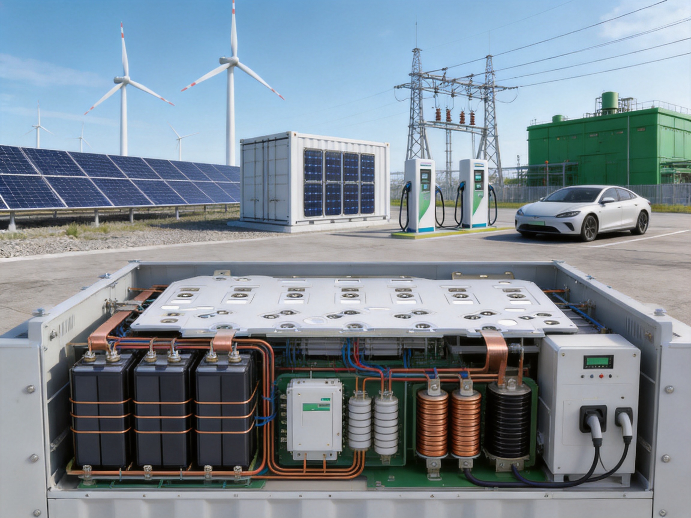
Solar photovoltaic and wind power systems use inverters, converters, transformers, energy storage units, and distribution equipment that require reliable internal current paths. Laminated busbars can connect DC sources, capacitors, switching devices, and output stages while supporting compact enclosure design.
In central and series inverters, the busbar helps organize high-current connections between input stages, DC-link capacitors, power modules, and output conversion circuits. Low inductance is valuable because switching behavior can affect efficiency, voltage stress, and electromagnetic compatibility.
9.2 Battery Energy Storage Systems
Battery energy storage systems require controlled electrical connections between cells, modules, racks, power conversion systems, contactors, fuses, and monitoring equipment. The laminated busbar can be used in the power distribution sections where current levels and packaging requirements exceed the practical capability of ordinary cables.
Because energy storage equipment may operate continuously and undergo frequent charge and discharge cycles, thermal stability and connection reliability are important. Customized terminal layouts can support serviceability and help integrate the busbar with protective components and monitoring circuits.
9.3 Electric Vehicle Charging Stations
High-power charging stations must transfer substantial current while maintaining safe insulation and efficient thermal management. A compact laminated busbar can connect rectifiers, power modules, DC conversion stages, and output distribution points within a limited cabinet volume.
Reduced wiring complexity can support faster assembly and easier maintenance. The busbar can also be designed to accommodate charging module layouts, cooling structures, protective barriers, and service access requirements.
9.4 Green Industrial Plants
Low-carbon manufacturing facilities increasingly rely on variable-frequency drives, energy-efficient motors, power quality equipment, solar generation, battery storage, and intelligent distribution systems. Composite laminated busbars can serve as internal connections in this equipment and support more compact power architecture.
Industrial applications may also benefit from the product’s durability, controlled insulation, and customized mechanical design. The appropriate material and surface treatment can be selected according to humidity, dust, temperature, vibration, and chemical exposure conditions.
9.5 Smart Grids and Microgrids
Smart grid and microgrid equipment integrates multiple power sources, storage devices, loads, converters, and control systems. Compact, low-inductance interconnections help equipment designers manage power flow while keeping cabinets organized.
As microgrids become more modular, standardized customized busbar designs can support repeatable equipment platforms. The busbar can be adapted for different current levels, terminal arrangements, and enclosure configurations.
9.6 Commercial Green Buildings
Commercial buildings increasingly use energy management systems, photovoltaic generation, battery storage, high-efficiency HVAC equipment, and electric vehicle infrastructure. Laminated busbars can be used within power conversion and distribution equipment to improve space utilization and simplify internal wiring.
In buildings where equipment rooms are limited, compact electrical assemblies may help reduce cabinet size and installation complexity. Reliable connections also support continuous operation and easier planned maintenance.
9.7 Environmental Protection Equipment
Waste treatment, energy recovery, water treatment, air purification, and emissions-control systems use motors, drives, converters, heaters, pumps, and control equipment. These systems often operate for long periods in demanding environments.
A customized composite laminated busbar can provide a stable internal current path while supporting insulation and service-life requirements. The design should be adapted to the temperature, humidity, corrosive substances, and vibration conditions of each installation.
10. Installation and Integration Considerations
Proper installation is necessary to realize the performance advantages of a laminated busbar. Before installation, the customer should confirm the busbar’s orientation, terminal identification, mounting locations, insulation clearances, and compatibility with adjacent components.
Fasteners should be selected according to the specified thread, material, length, and tightening torque. Excessive torque can deform terminals or damage insulation, while insufficient torque may increase contact resistance and allow movement during operation. If washers, spacers, or locking devices are required, they should be installed exactly as indicated in the assembly documentation.
The busbar should not be forced into position or bent after lamination unless the design specifically allows such adjustment. Unplanned mechanical stress may damage internal insulation or weaken terminal areas. Equipment designers should provide adequate tolerance and access so that the busbar can be installed without interference.
Clearance and creepage distances must be verified after the busbar is installed inside the enclosure. Nearby metal parts, fasteners, cooling plates, circuit boards, and cable terminals should not reduce the required insulation distances. Final system testing should include continuity, insulation, polarity, and dielectric checks as appropriate.
Thermal validation is also recommended. The actual temperature rise depends on current profile, ambient conditions, ventilation, enclosure design, contact resistance, and nearby heat sources. Prototype testing under representative operating conditions helps confirm that the selected busbar configuration is suitable for the complete system.
11. Customization Services
Customized manufacturing is one of the most important advantages of working with an experienced busbar supplier. Each application may require a different conductor thickness, number of layers, insulation material, terminal style, hole pattern, plating treatment, or dimensional envelope.
Customization may include:
• Conductor material and thickness selection.
• Positive, negative, or multiphase laminated configurations.
• Customized overall length, width, and height.
• Special terminal shapes and connection holes.
• Integrated bends, offsets, and three-dimensional profiles.
• Tin plating or other specified surface treatments.
• Flame-retardant, high-temperature, or application-specific insulation.
• Additional insulating covers and protective barriers.
• Markings, labels, polarity identification, and traceability codes.
• Prototype development and design-for-manufacturing review.
The engineering process normally begins with customer drawings, electrical schematics, three-dimensional models, or sample components. When the customer does not yet have a complete design, the manufacturer can assist with current-path planning, terminal arrangement, layer structure, insulation layout, and production feasibility.
Design-for-manufacturing analysis is important because a busbar that performs well in a computer model may still be difficult to produce or install. Engineers review bend radii, tool access, lamination boundaries, plating areas, inspection methods, and packaging constraints. Early review can reduce redesign cycles and shorten the route from prototype to production.
12. Quality Management and Validation
Quality control should cover the entire production chain rather than relying only on final inspection. Incoming materials, machining, surface treatment, insulation preparation, lamination, assembly, and testing each require defined controls.
Incoming copper should be checked for material identity, thickness, surface condition, and traceability. Insulation materials should be confirmed against the approved specification, including thickness, temperature class, dielectric properties, and appearance.
In-process inspection can verify cutting dimensions, hole positions, forming angles, burr condition, plating coverage, layer alignment, and lamination parameters. These checks help identify problems before additional value is added to the product.
Final inspection may include visual examination, dimensional measurement, conductor continuity, contact resistance, insulation resistance, dielectric withstand, and documentation review. Depending on the application, customers may also request thermal cycling, vibration, humidity, salt spray, or long-duration load tests.
Traceability is valuable for both quality assurance and continuous improvement. If a field issue occurs, production records can help identify material batches, process conditions, inspection results, and corrective actions. A documented feedback loop enables the manufacturer to improve future designs and reduce recurrence.
13. Supporting Sustainable Business Objectives
Businesses adopting renewable energy, energy storage, and low-carbon production technologies often need suppliers that understand both technical performance and environmental goals. The Eco-Friendly Composite Laminated Busbar supports this direction by combining material efficiency, low-loss power distribution, long service life, and compact design.
Its contribution to sustainability is not limited to the product label. A properly engineered busbar can help reduce energy losses during operation, simplify the equipment structure, limit the use of separate auxiliary components, and improve maintainability. These benefits can contribute to a lower total environmental impact over the product life cycle.
For equipment manufacturers, sustainable design can also support commercial objectives. Compact components may reduce cabinet size, simplify assembly, and lower logistics requirements. Reliable connections can reduce warranty exposure and service interruptions. Consistent manufacturing can improve yield and reduce material waste in high-volume production.
Environmental claims should always be evaluated with appropriate documentation. Customers may request material declarations, recycling information, restricted-substance compliance, process data, or life-cycle information. The manufacturer can work with customers to identify the relevant environmental and regulatory requirements for the target market.
14. Recommended Selection Process
Selecting a laminated busbar begins with defining the electrical requirements. These include continuous current, peak current, voltage, switching frequency, short-circuit conditions, duty cycle, and expected temperature rise. The design team should also identify whether current is DC, AC, pulsed, or rapidly switching.
The mechanical requirements should then be documented. Important details include available space, mounting points, terminal orientation, enclosure dimensions, service access, vibration, thermal expansion, and interaction with cooling components. A three-dimensional equipment model is useful for detecting interference before prototype production.
Insulation requirements should cover working voltage, transient voltage, pollution level, altitude, creepage distance, clearance, dielectric test level, partial discharge expectations, and operating temperature. If the product will be used in a humid, dusty, corrosive, or high-vibration environment, these conditions should be communicated at the beginning of the project.
Finally, the customer and manufacturer should agree on inspection standards, packaging, labeling, documentation, delivery schedule, prototype quantity, and production volume. Clear requirements reduce misunderstandings and help establish a stable quality baseline.
15. Frequently Asked Questions
Q1. What is a composite laminated busbar?
A composite laminated busbar is an integrated electrical conductor assembly made from one or more conductive layers and insulating layers that are aligned and bonded into a compact structure. It is used to distribute electrical power inside equipment while controlling insulation, inductance, mechanical arrangement, and connection geometry.
Q2. What makes this busbar eco-friendly?
The product is designed around recyclable material options, low-loss current distribution, compact construction, long service life, and eco-conscious manufacturing. These characteristics can help reduce material waste, operating losses, replacement frequency, and the environmental burden of auxiliary components. Specific environmental performance should be confirmed for the selected materials and project requirements.
Q3. What are the referenced electrical ratings?
The referenced configuration has a rated voltage of 540 VDC, a rated current of 200 A, and an insulation withstand voltage of 3.5 kVDC for 60 seconds with leakage below 2 mA under the stated test condition. Final ratings depend on the completed design, installation environment, temperature rise, and customer qualification requirements.
Q4. Why is lower inductance important?
Lower inductance can reduce voltage overshoot and ringing during rapid current changes. This is valuable in inverter, converter, energy storage, and charging applications that use fast-switching power semiconductor devices. The complete system must still be analyzed because switching performance depends on the busbar, capacitors, devices, grounding, control strategy, and enclosure.
Q5. Can the busbar be customized?
Yes. Customization may include dimensions, copper thickness, layer arrangement, terminal geometry, mounting holes, bends, insulation material, surface treatment, protective covers, and markings. Design support can be provided using drawings, three-dimensional models, electrical schematics, or samples.
Q6. Is tin plating necessary for every application?
Not necessarily. Tin plating is used in the referenced configuration and can provide surface protection and a reliable electrical interface. The best surface treatment depends on current, environment, mating materials, contact method, corrosion conditions, and customer specifications.
Q7. How does a laminated busbar reduce installation cost?
It can reduce the number of separate cables, insulating barriers, spacers, fasteners, and routing operations. It also provides a repeatable assembly that can be installed more quickly and with fewer opportunities for wiring errors. The actual cost benefit depends on product volume, system complexity, and installation method.
Q8. Can it be used in battery energy storage systems?
Yes. The product is suitable for selected power distribution and converter connections in battery energy storage systems. The design must be matched to the battery voltage, current, insulation system, thermal environment, fault conditions, and applicable safety standards.
Q9. What tests should be performed before mass production?
Typical validation may include dimensional inspection, continuity, contact resistance, insulation resistance, dielectric withstand, temperature rise, vibration, thermal cycling, humidity exposure, and partial discharge testing where applicable. The exact program should be defined according to the final equipment and market requirements.
Q10. What information should a customer provide for a quotation?
Useful information includes electrical ratings, current waveform, drawings or three-dimensional models, terminal requirements, dimensions, insulation class, operating temperature, environmental conditions, estimated annual volume, surface treatment, testing requirements, and packaging expectations.
Q11. Can the supplier support prototypes as well as mass production?
The company provides product design, research and development, manufacturing, testing, and solution capabilities. This supports a project path from engineering review and prototype development to process stabilization and repeat production, subject to the complexity and requirements of the individual project.
Q12. What industries can use this product?
Potential industries include renewable energy, photovoltaic and wind power, battery energy storage, electric vehicle charging, industrial automation, green manufacturing, smart grids, microgrids, commercial buildings, rail transit, communication power systems, and environmental protection equipment.
16. Conclusion
The Eco-Friendly Composite Laminated Busbar is an engineered solution for modern power distribution systems that require more than basic conductivity. Its composite structure combines copper conductors, controlled insulation, compact geometry, and customized connection features to support safe and efficient equipment design.
Compared with loose cable assemblies, it can provide a more organized current path, lower inductance, improved electromagnetic behavior, reduced assembly complexity, and better space utilization. Compared with uninsulated rigid busbars, it integrates insulation and can reduce the need for separate protective components. Compared with generic standard products, it can be designed around the exact electrical and mechanical requirements of the customer’s equipment.
Its environmental advantages are connected to recyclable material options, low-loss operation, durable construction, and reduced system complexity. These features make it relevant to companies developing renewable energy equipment, battery storage systems, EV charging infrastructure, green industrial equipment, smart grid products, and energy-efficient commercial systems.
The manufacturing foundation is equally important. Experienced engineering teams, precision machining, controlled surface treatment, accurate layer alignment, composite lamination, advanced connection technologies, and comprehensive testing help transform a design concept into a dependable production component. The manufacturer’s background in new energy conductive components, battery soft connections, polymer diffusion welding, laser technology, and multidisciplinary research supports its ability to serve demanding customized projects.
For customers seeking a reliable and sustainable alternative to conventional internal wiring, the product offers a balanced combination of electrical performance, mechanical integration, manufacturing consistency, and environmental responsibility. With appropriate application analysis and system-level validation, the Eco-Friendly Composite Laminated Busbar can become a valuable part of the next generation of safe, compact, and efficient power equipment.
References
1. IEC 60664-1, Insulation Coordination for Equipment within Low-Voltage Systems.
2. IEC 61439, Low-Voltage Switchgear and Controlgear Assemblies.
3. IEC 62477-1, Safety Requirements for Power Electronic Converter Systems and Equipment.
4. IPC-2221, Generic Standard on Printed Board Design and Electrical Clearance Principles.
5. IEEE guidance on electromagnetic compatibility, power electronics, and high-current interconnection design.
6. General engineering principles for laminated busbar design, thermal management, dielectric insulation, and low-inductance power distribution.
7. Manufacturer-provided product specifications and company technical information for composite laminated busbars and new energy conductive components.
Product: Eco-Friendly Composite Laminated Busbar

Driven by the development of new energy and aiming for "zero carbon".
Copyright © Zhejiang Zhongyan New Energy Co., Ltd. All Rights Reserved.
