 English
 Español

PBC Series Soft Braided Tape: Flexible High-Current Connections for Advanced Power Systems
Modern electrical and energy-storage systems increasingly require conductive components that combine high current capacity, mechanical flexibility, low electrical resistance, and dependable service life. Traditional rigid busbars remain valuable for fixed connections, but they are not always suitable where equipment experiences vibration, thermal expansion, assembly tolerances, or repeated movement. In these applications, a flexible braided connection can provide a more reliable and practical alternative.
The PBC Series Soft Braided Tape is designed for flexible power connections in electrical equipment, power-distribution assemblies, renewable-energy systems, battery systems, industrial machinery, and other high-current applications. Manufactured from tinned copper stranded wire with an individual wire diameter of 0.15 mm, the product provides a broad conductive cross section while retaining the flexibility required for installation and service.
Each PBC product is formed as a crimped assembly with integrated, undrilled joints that can be produced according to a customer’s specific design. This approach enables the connection to be adapted to different busbar arrangements, terminal locations, equipment clearances, and installation requirements. The result is a soft, high-conductivity connection that can compensate for movement and dimensional variation without relying on a rigid conductor alone.
With available cross-sectional areas from 100 mm² to 1,200 mm², the PBC Series covers a broad range of current-carrying requirements. Depending on the selected model and the allowable temperature rise, the listed current-carrying capacity ranges from hundreds of amperes to more than 3,000 amperes. This makes the series suitable for both compact power assemblies and large-scale high-current applications.

PBC Series Soft Braided Tape
Content
- What Is Soft Braided Tape?
- Core Product Advantages
- Applications in Electrical and Energy Systems
- Electrical Performance and Thermal Considerations
- Product Range and Technical Selection
- Manufacturing Process and Engineering Strengths
- Advantages Over Conventional Alternatives
- Installation Recommendations
- Reliability, Maintenance, and Service Life
- Support for OEM and Project-Based Development
- Why the PBC Series Is Suitable for New-Energy Applications
- Engineering Checklist for Product Selection
- Frequently Asked Questions
- What is the PBC Series Soft Braided Tape used for?
- What material is used in the braided conductor?
- What cross-sectional sizes are available?
- What current can the PBC Series carry?
- Can the product be customized?
- Why are the joints undrilled?
- Can two PBC connections be installed in parallel?
- Is the PBC Series suitable for battery packs?
- How should the flexible braid be installed?
- What information is needed for a quotation or custom design?
- How does the PBC Series compare with a rigid busbar?
- How does the product compare with a large-gauge cable?
- What should be checked during maintenance?
- Conclusion
- References
- Product: PBC Series Soft Braided Tape
What Is Soft Braided Tape?
Soft braided tape is a flexible electrical conductor made by arranging many fine copper wires into a braided or woven structure. Unlike a solid copper strip, the individual wires can move slightly relative to one another. This construction allows the conductor to bend, twist, compress, and accommodate movement while maintaining a continuous electrical path.
The PBC Series uses tinned copper stranded wire with a nominal individual wire diameter of 0.15 mm. Fine wire construction is important because smaller wire diameters generally provide greater flexibility than a small number of larger conductors. The tin coating also supports improved surface protection and stable contact performance in many industrial environments.
The ends of the braided conductor are formed into integrated joints through a controlled crimping process. These joints are supplied undrilled, allowing the final connection geometry to be matched to the customer’s design. Depending on the application, customers may specify the required overall length, cross-sectional area, terminal dimensions, hole arrangements, contact surfaces, and installation orientation.
The term “soft” does not indicate weak or unstable construction. It refers primarily to the mechanical behavior of the conductor. A properly engineered soft connection can carry substantial current while allowing controlled movement. Its flexibility helps prevent excessive mechanical stress from being transferred to terminals, insulators, battery housings, or rigid busbars.
Core Product Advantages
High Current Capacity
The main function of the PBC Series is to provide a dependable conductive path for high-current systems. The available cross sections include 100, 120, 150, 200, 250, 300, 400, 500, 600, 800, 1,000, and 1,200 mm². This range allows engineers to select a conductor according to current demand, space limitations, thermal conditions, and required safety margins.
At a 30 K temperature rise, the listed current-carrying capacities range from 349 A for the 100 mm² version to 1,982 A for the 1,200 mm² version. At a 50 K temperature rise, the listed capacities range from 600 A to 3,170 A. These values provide useful reference points during preliminary design, although the final rating must always be verified against installation conditions, ventilation, contact resistance, ambient temperature, duty cycle, and applicable standards.
Compared with a single rigid strip of equivalent electrical capacity, a braided conductor can provide current transfer while also absorbing movement. This is especially useful in systems where current must pass between components that cannot remain perfectly aligned throughout their operating life.
Exceptional Flexibility
Flexibility is the defining advantage of the PBC Series. Fine tinned copper strands create a conductor that can be routed through confined spaces and positioned around mechanical obstacles. This can simplify assembly and reduce the need for complex rigid-busbar shapes.
A flexible connection can also accommodate vibration and thermal expansion. Electrical equipment often heats during operation and cools after shutdown. Copper, aluminum, steel, polymers, and battery materials expand at different rates. If two rigid components are joined without sufficient allowance for movement, the resulting stress can be transmitted to fasteners and terminals. A soft braided connection helps absorb this relative movement.
The product is suitable for flexible connections between power supplies, busbars, expansion rings, battery terminals, and other conductive components. It can also be used where access for installation is limited or where the connection must be bent into position after surrounding components have been installed.
Low Mechanical Stress on Connected Equipment
A rigid conductor can act as a structural member. When equipment vibrates, shifts, or expands, the conductor may exert force on the connected parts. Over time, these forces may contribute to terminal loosening, cracking, deformation, or fatigue in sensitive components.
The PBC Series separates electrical conduction from unnecessary mechanical rigidity. The braided structure carries current while allowing controlled flexibility. This reduces the mechanical load imposed on connection points and can improve the reliability of the complete assembly.
This characteristic is particularly valuable in battery packs, power converters, switchgear, rail equipment, electric vehicles, and industrial equipment exposed to vibration or frequent thermal cycling. In these systems, connection reliability depends not only on electrical conductivity but also on the ability to withstand mechanical and environmental stress.
Design Flexibility Through Customized Joints
The integrated joints are produced without pre-drilled holes as a standard design feature. Undrilled joints allow the connection to be customized instead of forcing the customer to adapt the rest of the equipment to a fixed terminal pattern.
Customized joint designs may help address unusual center distances, nonstandard mounting surfaces, limited installation clearances, different bolt patterns, or special orientation requirements. The design can be developed according to the customer’s drawings, technical specifications, sample, or application requirements.
This approach is especially useful for original equipment manufacturers and system integrators. Rather than selecting a generic flexible strap and modifying it in the field, the customer can receive a connection designed for the intended assembly. Properly matched joint geometry can reduce installation time, avoid unnecessary bends, and improve contact consistency.
Protection Provided by Tinned Copper Strands
The PBC Series uses tinned copper stranded wire. Copper provides high electrical conductivity and is widely used in power-distribution and energy-storage applications. The tin coating offers an additional protective surface that can support long-term contact stability and help reduce the risk of surface deterioration under suitable operating conditions.
Tinned copper is also compatible with many common joining and terminal practices. It can be integrated into crimped connection structures and used with appropriately selected bolts, washers, contact surfaces, and protective materials. Engineers should still evaluate galvanic compatibility when the braid is connected to dissimilar metals such as aluminum, particularly in humid, salt-contaminated, or chemically aggressive environments.
The use of fine strands increases flexibility, while the conductive copper core supports efficient current transfer. Together, these features make the material suitable for applications where both electrical performance and mechanical compliance are required.
Applications in Electrical and Energy Systems
Power Distribution Equipment
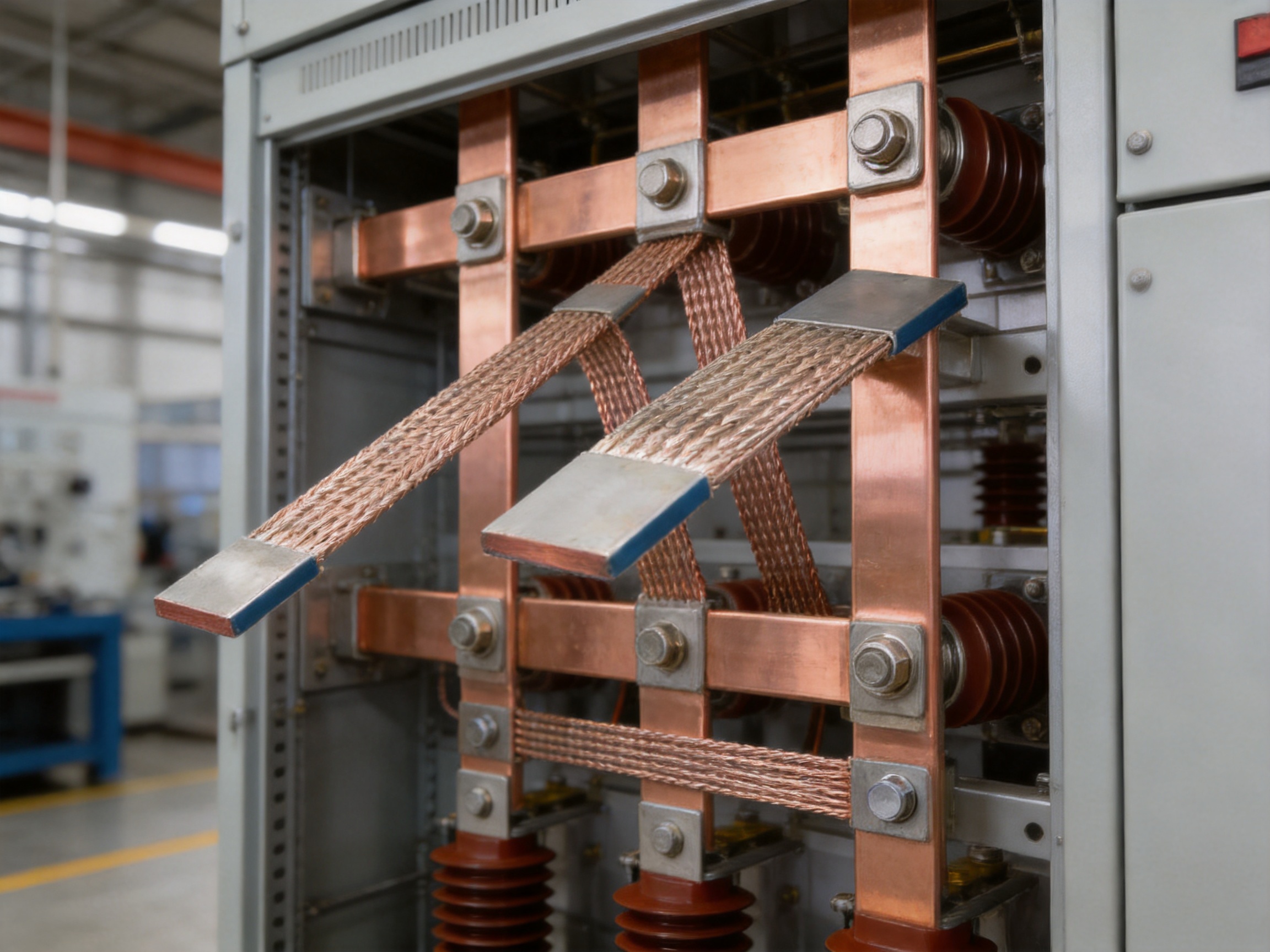
Power-distribution equipment often contains rigid busbars, breakers, switches, terminals, and expansion components. A flexible braided connection can link these components while accommodating movement caused by thermal cycling, vibration, or installation tolerances.
In switchboards and distribution cabinets, the PBC Series can be used between a rigid busbar and a movable or removable section. It may also be applied around expansion joints or in areas where a rigid conductor would require several bends. The flexible structure can simplify routing and reduce the risk of misalignment during assembly.
Busbar Expansion Connections
Long conductors and high-current busbars may experience measurable thermal expansion. Expansion rings and flexible links are used to prevent this movement from placing excessive force on fixed supports. The PBC Series is suitable for flexible power connections involving expansion rings and busbar assemblies.
When selecting the product for expansion applications, designers should consider the expected movement range, direction of movement, minimum bend radius, attachment method, and number of parallel connections. The flexible conductor should be installed so that it moves naturally rather than being forced into a sharp bend or compressed against adjacent components.
Battery Packs and Energy Storage
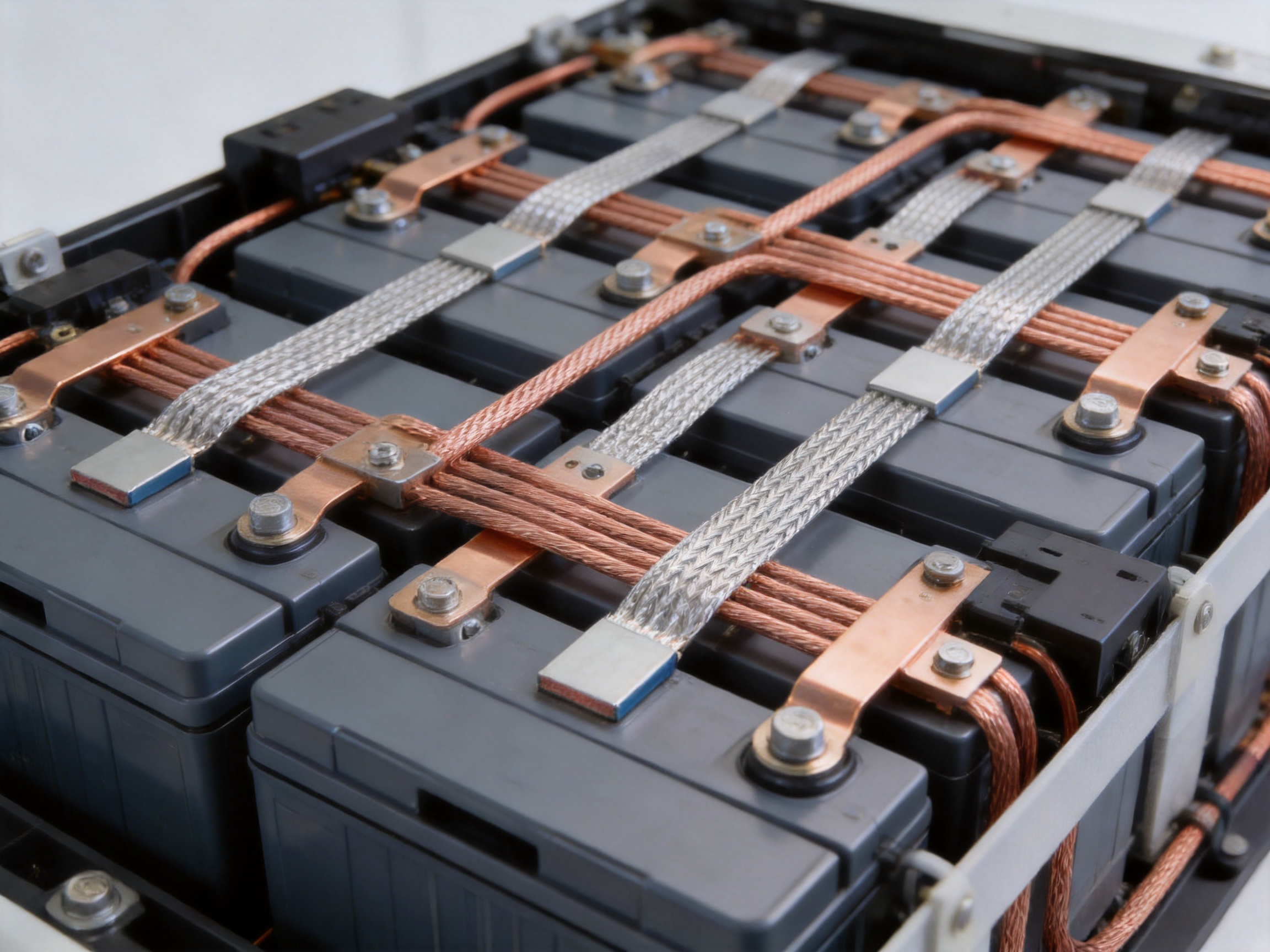
Battery systems require conductive connections that occupy limited space while handling substantial current. Battery modules may expand and contract during charge and discharge, and the complete pack may be exposed to vibration, shock, or changes in temperature. A flexible braided link can help isolate terminals from these mechanical influences.
The PBC Series can be considered for connections between battery modules, busbars, power terminals, disconnect devices, and energy-storage components. Its customizable joint design supports different battery layouts and mounting patterns. In a properly engineered battery assembly, flexible connections may improve serviceability and reduce stress on cell or module terminals.
Battery applications require careful attention to insulation, short-circuit protection, creepage and clearance, fault current, thermal management, and assembly torque. A flexible conductor should never be treated as an isolated component; it must be integrated into a complete battery safety design.
Electric Vehicles and Transportation Equipment
Electric vehicles and rail systems contain high-current paths that may be exposed to vibration, repeated acceleration, braking forces, and thermal cycling. Flexible copper connections can be used between battery components, inverters, converters, distribution units, and other high-power assemblies.
The PBC Series can help accommodate limited alignment variation and reduce the transfer of vibration to sensitive terminals. Its compact, customizable construction can also support efficient packaging where space is restricted.
Transportation applications require validation under relevant vibration, temperature, insulation, current, and environmental conditions. The product dimensions and current values should be reviewed together with the vehicle or equipment manufacturer’s qualification requirements.
Industrial Machinery and Automation
Industrial machinery often includes moving assemblies, motors, drives, heating equipment, and high-current power terminals. Flexible braided connections can be installed where a conductive path must tolerate movement or where frequent maintenance requires the equipment to be disconnected and repositioned.
Compared with a rigid connection that must be carefully aligned, a flexible connection can make maintenance access easier. It may also reduce installation errors caused by small dimensional differences between production batches or machine components.
Renewable Energy Systems
Solar power, wind power, and energy-storage systems frequently combine high-current conductors with outdoor or semi-outdoor operating conditions. Flexible links can be useful in inverters, combiner equipment, battery containers, switchgear, and power-conversion cabinets.
In these applications, designers should evaluate exposure to moisture, temperature variation, ultraviolet radiation, salt atmosphere, dust, and condensation. The flexible braid should be protected and installed in a way that prevents water accumulation, abrasion, and contamination of contact surfaces.
Electrical Performance and Thermal Considerations
Current-carrying capacity is influenced by more than cross-sectional area. The temperature rise of a conductor depends on current, resistance, contact quality, ambient temperature, airflow, installation orientation, proximity to other heat sources, and the duration of the load.
The PBC Series data provides current-carrying values at temperature rises of 30 K and 50 K. The lower temperature-rise value is useful when the application requires tighter thermal control. The higher value may be considered for applications where a greater conductor temperature rise is acceptable within the system’s design limits.
For example, the PBC 100x250 model has a listed current capacity of 349 A at a 30 K temperature rise and 600 A at a 50 K temperature rise. The PBC 500x400 model is listed at 917 A and 1,561 A under the same two conditions. The PBC 1,200x500 model reaches listed values of 1,982 A and 3,170 A.
These figures should not be interpreted as universal ratings for every installation. A braided conductor installed in open air may perform differently from one enclosed in a cabinet. Parallel conductors may improve current distribution, but only when they are installed with appropriate geometry and equalized connection resistance.
Thermal design should include an evaluation of the entire current path. A low-resistance braid connected to a poorly prepared terminal can still produce excessive heat at the joint. Contact surfaces should be clean, flat, correctly sized, and tightened using the specified assembly procedure.
Parallel Installation
The product information specifies that when two soft connections are used in parallel, the minimum interval between the two connections must be equal to the thickness of the diverter for air cooling. This requirement is important because spacing affects airflow and heat dissipation.
Parallel flexible connections should be arranged symmetrically whenever possible. Equal lengths and similar contact conditions help distribute current more evenly. If one connection has significantly lower resistance, it may carry a disproportionate share of the current and run hotter than the others.
Designers should also allow enough space for inspection, tightening, insulation, and natural movement. Parallel conductors should not be packed so closely that the braid becomes compressed or airflow is obstructed.
Product Range and Technical Selection
The following table summarizes the available PBC Series models based on the supplied product information. The listed current values correspond to the stated 30 K and 50 K temperature-rise conditions. The dimensional fields are reproduced as provided and should be confirmed against the applicable drawing before production approval.
| Part Number | Description | Cross Section (mm²) | Current at Δ30 K (A) | Current at Δ50 K (A) | Listed A | Listed B | Listed C | Listed L | Listed Value | Length (mm) | Quantity | Weight (kg) |
|---|---|---|---|---|---|---|---|---|---|---|---|---|
| 23000415 | PBC 100x250 | 100 | 349 | 600 | 462 | 795 | 35 | 40 | 7.0 | 250 | 2 | 0.38 |
| 23000416 | PBC 100x500 | 100 | 349 | 600 | 462 | 795 | 35 | 40 | 7.0 | 500 | 2 | 0.63 |
| 23000417 | PBC 120x250 | 120 | 385 | 670 | 511 | 877 | 35 | 40 | 7.5 | 250 | 2 | 0.42 |
| 23000418 | PBC 150x250 | 150 | 440 | 757 | 583 | 1003 | 55 | 50 | 8.0 | 250 | 2 | 0.63 |
| 23000419 | PBC 150x500 | 150 | 440 | 757 | 583 | 1003 | 55 | 50 | 8.0 | 500 | 2 | 0.90 |
| 23000420 | PBC 200x250 | 200 | 550 | 946 | 729 | 1253 | 55 | 50 | 9.0 | 250 | 2 | 0.76 |
| 23000421 | PBC 200x500 | 200 | 550 | 946 | 729 | 1253 | 55 | 50 | 9.0 | 500 | 2 | 1.20 |
| 23000422 | PBC 250x300 | 250 | 651 | 1120 | 863 | 1484 | 85 | 50 | 10.5 | 300 | 2 | 1.03 |
| 23000423 | PBC 300x400 | 300 | 716 | 1180 | 948 | 1565 | 85 | 60 | 11.0 | 400 | 1 | 1.53 |
| 23000424 | PBC 400x400 | 400 | 853 | 1360 | 1131 | 1808 | 85 | 80 | 11.0 | 400 | 1 | 2.20 |
| 23000425 | PBC 500x400 | 500 | 917 | 1561 | 1216 | 1944 | 105 | 100 | 11.0 | 400 | 1 | 2.64 |
| 23000426 | PBC 600x450 | 600 | 1101 | 1762 | 1459 | 2334 | 105 | 100 | 13.0 | 450 | 1 | 3.40 |
| 23000427 | PBC 800x450 | 800 | 1376 | 2202 | 1823 | 2917 | 105 | 100 | 14.0 | 450 | 1 | 4.26 |
| 23000428 | PBC 1000x450 | 1000 | 1651 | 2642 | 2188 | 3500 | 105 | 100 | 16.0 | 450 | 1 | 5.47 |
| 23000429 | PBC 1200x500 | 1200 | 1982 | 3170 | 2626 | 4208 | 125 | 120 | 17.5 | 500 | 1 | 7.16 |
Choosing the Cross Section
Cross-section selection should begin with the continuous operating current. Engineers should then consider overload duration, short-term peak current, ambient temperature, enclosure conditions, allowable temperature rise, cooling method, and required service life.
A larger cross section may be appropriate when the connection operates continuously at high load, when airflow is restricted, or when lower voltage drop and lower heat generation are priorities. A smaller cross section may be suitable for intermittent loads or compact assemblies, provided that the complete thermal and mechanical design supports the selection.
Current capacity alone should not determine the product choice. The connection must also fit the available space, maintain the required bend radius, support the expected movement, and provide sufficient contact area at both ends.
Choosing the Length
The listed product range includes lengths from 250 mm to 500 mm, with additional dimensions available through customized manufacturing. The correct length should permit installation without tension while avoiding excessive slack that could create unwanted movement or contact with adjacent parts.
A connection that is too short may be forced into a sharp bend or placed under constant tensile stress. A connection that is too long may sag, rub against nearby components, or create an avoidable electromagnetic and thermal arrangement issue. The ideal length follows the natural route between the two connection points and allows the braid to flex smoothly.
Choosing Joint Geometry
Joint dimensions should be selected according to the mating busbar, terminal, or equipment interface. Important factors include contact width, bolt diameter, hole spacing, mounting orientation, available clearance, washer size, and the need for insulating barriers.
Because the standard integrated joints are undrilled, customers can discuss the required final design before production. A dimensionally accurate drawing or sample can help ensure that the finished part fits the assembly without field modification.
Manufacturing Process and Engineering Strengths
The performance of a soft braided connection depends heavily on manufacturing consistency. Fine copper wires must be formed into a uniform conductive structure, the joint area must be properly compressed, and the finished assembly must maintain stable dimensions from piece to piece.
The manufacturer specializes in new-energy conductive components, including high-voltage electrical copper-foil flexible connections, special-shaped flexible connections, battery flexible connections, and other precision components. This specialization provides an application-oriented foundation for developing braided connectors used in demanding electrical systems.
Material Preparation
Manufacturing begins with the selection and preparation of conductive copper wire. The PBC Series uses tinned copper stranded wire with a nominal diameter of 0.15 mm. Material control is important because variations in wire diameter, coating quality, tensile strength, and surface condition can influence flexibility, resistance, and joint performance.
Incoming materials should be checked against technical requirements before production. Typical controls may include visual inspection, dimensional verification, coating inspection, resistance testing, and documentation review. Consistent raw materials create a stable foundation for the subsequent braiding and crimping operations.
Precision Braiding
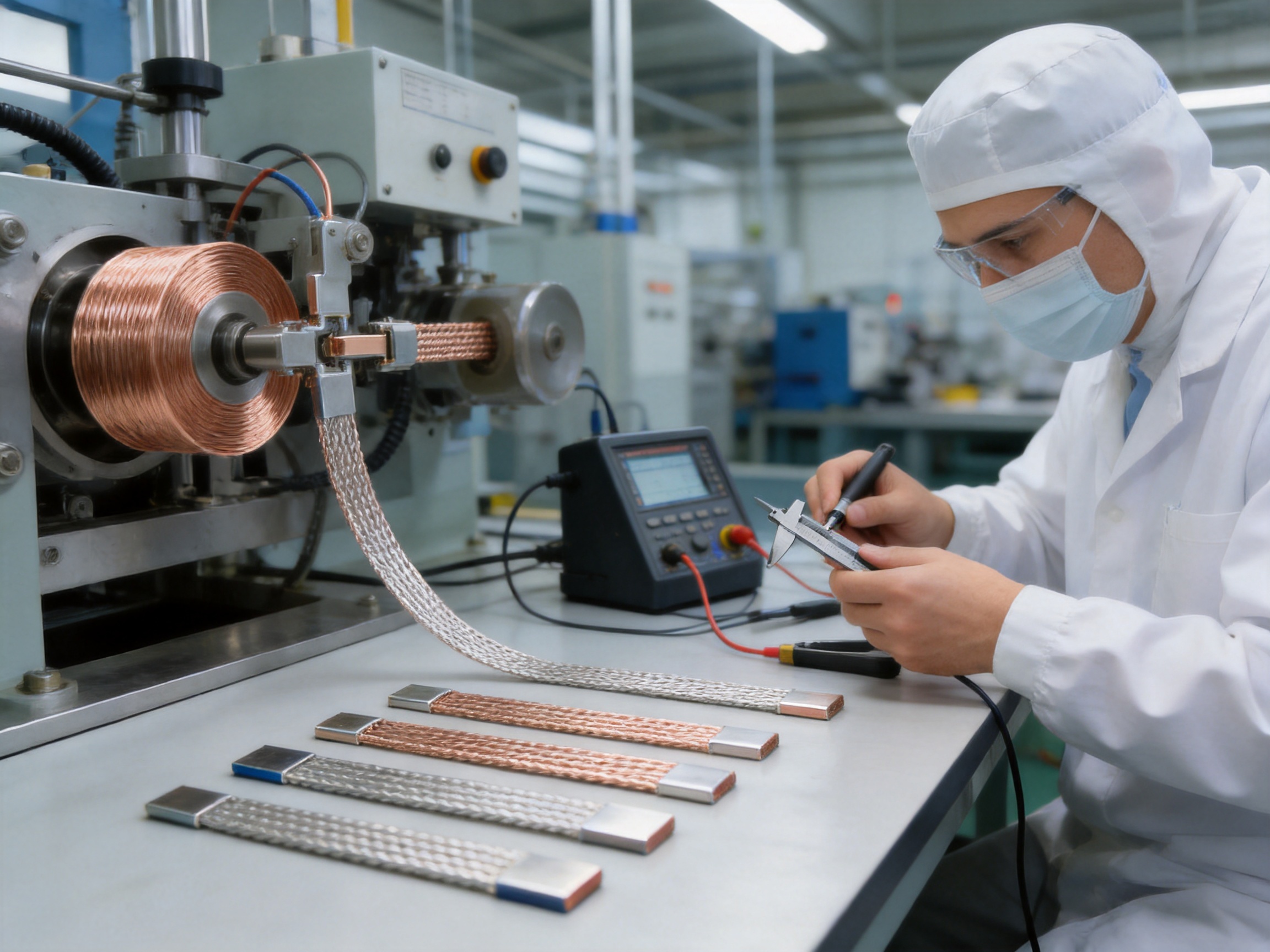
The fine wires are arranged into a braided tape structure using specialized equipment. Braiding parameters influence the width, thickness, density, flexibility, and electrical performance of the finished conductor.
A controlled process helps maintain a uniform cross section along the length. Consistency is important because local reductions in material density can increase resistance and produce hot spots. Excessive compaction, on the other hand, may reduce flexibility and make the connection more difficult to install.
Production engineers can adjust the braid structure according to the target cross section and application. High-current models require a greater amount of conductive material, while space-limited assemblies may require careful control of thickness and width.
Integrated Joint Crimping
The braided tape is formed into integrated joints through a controlled crimping process. Crimping consolidates the strands, creates a stable terminal area, and improves the connection between the flexible conductor and the mating hardware.
Crimping pressure, tooling condition, joint geometry, and material alignment all influence the finished result. Insufficient compression may leave internal voids or create inconsistent strand contact. Excessive compression may damage strands or produce an overly rigid transition zone. A controlled manufacturing process seeks a balance between electrical continuity and mechanical integrity.
The joint transition should also be designed carefully. A sudden change from flexible braid to rigid terminal can concentrate stress during bending. A well-formed transition distributes mechanical forces more gradually and supports longer service life under vibration and movement.
Customized Manufacturing
The company’s engineering capability supports customized production based on customer-specific designs. Customization may include cross section, length, joint width, terminal profile, hole pattern, plating requirements, insulation provisions, and packaging quantity.
Customized manufacturing is particularly advantageous for original equipment manufacturers. It allows the flexible connection to be considered during the equipment design stage rather than treated as an afterthought. This can improve space utilization, reduce assembly steps, and help standardize the connection across product families.
Engineering support may include drawing review, material recommendations, prototype development, sample verification, process optimization, and batch production. The objective is to convert the customer’s electrical and mechanical requirements into a repeatable production design.
Polymer Diffusion Welding and Laser Technology
The manufacturer has developed capabilities involving polymer diffusion welding and laser technology for new-energy precision components. These technologies support the production of low-resistance, high-reliability connection systems in applications where accurate joining and controlled heat input are essential.
Although every PBC configuration must be evaluated according to its own manufacturing route, the broader technology base is valuable for customized conductive components. It indicates experience with precision joining, material compatibility, thermal control, and high-reliability production for battery and energy applications.
Quality Management and Testing
Quality control should cover the complete product rather than only the raw copper material. Typical inspection areas include overall dimensions, cross-sectional consistency, joint appearance, crimp integrity, surface condition, electrical resistance, mechanical strength, and packaging condition.
Electrical testing can identify excessive resistance or discontinuities. Dimensional inspection verifies that the connection will fit the intended assembly. Mechanical tests can evaluate joint strength and resistance to pulling or bending. Where required, environmental and thermal tests may be performed to confirm suitability for a specific application.
Traceability is also important for industrial and automotive supply chains. Material batches, production parameters, inspection records, and packaging information can help identify the source of any deviation and support continuous improvement.
Advantages Over Conventional Alternatives
Compared with Rigid Copper Busbars
Rigid copper busbars are efficient and durable when the connected points remain fixed and accurately aligned. However, they may require multiple bends, expansion features, or complex tooling when installed between components that move relative to one another.
The PBC Series offers greater flexibility and can be routed through constrained spaces. It can reduce the need for complex three-dimensional busbar shapes and may simplify assembly when terminal positions vary slightly.
Rigid busbars may still be the best choice for long, fixed, structurally supported current paths. A flexible braid is not intended to replace every rigid busbar. Its value is greatest at interfaces where movement, vibration, thermal expansion, or installation flexibility matters.
Compared with Generic Flexible Straps
Generic flexible straps may be available in limited sizes and fixed terminal configurations. Such products can require drilling, cutting, bending, or other field modifications. These modifications may damage the conductor, reduce the contact area, or create inconsistent installation quality.
The PBC Series is designed for customer-specific joint development. Its undrilled integrated joints provide a starting point for precise adaptation to the application. This can provide better control over the finished geometry than a standard strap that was not designed for the equipment.
The broad cross-sectional range is another advantage. Engineers can select a model more closely matched to the required current and available space instead of combining unsuitable products or using excessive parallel connections.
Compared with Large-Gauge Cables
Large-gauge cables offer flexibility and are widely used for power transfer. However, they may require cable lugs, bending space, strain relief, and larger routing channels. Their round shape may also be less suitable for flat, compact busbar arrangements.
A braided tape provides a flatter conductive profile and can be integrated directly into a joint structure. This may reduce the space required around the connection and support a more compact layout. The final choice depends on current, insulation, movement, bend requirements, environmental conditions, and applicable safety standards.
Installation Recommendations
Before installation, verify the part number, cross section, length, joint configuration, and drawing revision. Confirm that the connection is free from visible damage, contamination, sharp deformation, or abnormal strand separation.
Connection surfaces should be clean and properly aligned. The flexible braid should not be twisted unnecessarily or forced into a radius smaller than the approved design limit. It should be installed without permanent tensile loading unless the design specifically allows it.
Bolted joints should use the correct fasteners, washers, contact surfaces, and tightening torque. Excessive torque may distort the joint or mating busbar, while insufficient torque can increase contact resistance and lead to overheating. If the application is subject to vibration, an appropriate locking method should be selected according to the equipment design.
The braid should be protected from sharp edges, moving mechanisms, abrasive surfaces, and accidental contact with grounded or oppositely polarized conductors. Where insulation is required, the design should include suitable barriers, sleeves, covers, or molded protective components.
For parallel connections, maintain the recommended interval between the two soft connections. The minimum interval should be equal to the thickness of the diverter for air cooling, as stated in the product information. The installation should also promote balanced current sharing and adequate airflow.
Reliability, Maintenance, and Service Life
Flexible braided connections are often selected because they can improve reliability at mechanically sensitive interfaces. However, long service life depends on correct installation and system-level design.
During maintenance, technicians should inspect the braid for discoloration, broken strands, abrasion, corrosion, loose hardware, deformation, or signs of overheating. Any unusual color change near a joint may indicate excessive contact resistance or an overloaded connection.
Thermal imaging can be useful during commissioning and periodic inspection. A joint that operates significantly hotter than comparable connections may require investigation. Possible causes include insufficient tightening, contamination, damaged strands, uneven current distribution, restricted airflow, or operation above the intended rating.
In battery and energy-storage systems, inspection procedures should also consider insulation resistance, clearance, enclosure integrity, and the possibility of high fault current. Maintenance must be performed by qualified personnel following the system manufacturer’s safety procedures.
Environmental protection should be reviewed throughout the expected service life. Tinned copper provides useful surface protection, but it does not eliminate the need for suitable enclosure design, sealing, drainage, and material compatibility in aggressive environments.
Support for OEM and Project-Based Development
OEM customers often need more than a catalog part. They may require a complete development process that includes concept review, drawing confirmation, sample production, testing, approval, and stable mass production.
The manufacturer’s focus on precision conductive components supports this type of project. Experienced engineers can evaluate the electrical path, mechanical movement, available clearance, terminal design, thermal requirements, and production feasibility together.
A typical development process begins with the customer’s application data. Useful information includes operating current, peak current, voltage, ambient temperature, installation environment, terminal dimensions, expected movement, mounting method, insulation requirements, annual quantity, and applicable standards.
The engineering team can then propose a suitable cross section and joint design. Prototype samples allow the customer to confirm fit, flexibility, assembly method, and electrical performance. Feedback from prototype testing can be incorporated before production tooling and process parameters are finalized.
For repeated production, documented specifications help control consistency. The approved drawing should identify all critical dimensions, materials, surface treatments, inspection requirements, and packaging conditions. This creates a common reference for engineering, production, quality, and purchasing teams.
Why the PBC Series Is Suitable for New-Energy Applications
New-energy equipment is becoming more compact, more powerful, and more integrated. Battery modules, inverters, charging systems, and energy-storage cabinets must transfer high current while controlling heat and maintaining mechanical reliability.
The PBC Series addresses these requirements through a combination of high conductive capacity, fine-strand flexibility, customizable integrated joints, and production experience in new-energy connection components. Its design is compatible with applications where rigid conductors may transmit excessive stress or where cable-based solutions require too much routing space.
The product range also supports design scalability. A small system may use a 100 mm² or 150 mm² connection, while a high-power installation may require 600 mm², 800 mm², 1,000 mm², or 1,200 mm². The availability of multiple lengths and customized joint arrangements makes it easier to use the same general connection concept across different equipment platforms.
For system designers, this can simplify sourcing and standardization. For manufacturers, it may reduce the number of separate connection technologies required across a product family.
Engineering Checklist for Product Selection
Before placing an order, engineers should confirm the continuous current and any peak-current requirements. The selected rating should reflect the desired temperature-rise limit and the actual installation environment.
The required cross section should be checked against voltage-drop and power-loss targets. While the flexible braid is primarily selected for current transfer and mechanical compliance, resistance-related losses remain important in high-power systems.
The mechanical movement should be defined. This includes vibration, expansion, compression, bending, twisting, and any repeated movement caused by maintenance or operation. The connection should be long and flexible enough to accommodate the movement without fatigue.
The terminal interface should be documented with accurate dimensions. Hole spacing, hole size, contact width, joint thickness, bolt size, and orientation should all be confirmed before final production.
Thermal management should include airflow, spacing, nearby heat sources, enclosure conditions, and the use of parallel connections. The specified interval between parallel soft connections must be maintained where applicable.
Environmental requirements should cover temperature, humidity, condensation, salt spray, chemicals, dust, vibration, and insulation. Additional protection may be required depending on the application.
Finally, the customer should confirm inspection, testing, packaging, and documentation requirements. Clear technical communication at the design stage helps prevent costly modifications after production begins.
Frequently Asked Questions
What is the PBC Series Soft Braided Tape used for?
The PBC Series is used for flexible high-current electrical connections. Typical applications include busbar expansion links, power-supply connections, battery systems, energy-storage equipment, electrical distribution assemblies, industrial machinery, electric vehicles, rail equipment, and renewable-energy systems.
What material is used in the braided conductor?
The product uses tinned copper stranded wire with an individual wire diameter of 0.15 mm. The fine-strand structure provides flexibility, while the copper conductor supports high electrical conductivity.
What cross-sectional sizes are available?
The listed cross-sectional areas range from 100 mm² to 1,200 mm². Available sizes include 100, 120, 150, 200, 250, 300, 400, 500, 600, 800, 1,000, and 1,200 mm².
What current can the PBC Series carry?
The listed current-carrying capacity depends on the model and allowable temperature rise. At a 30 K temperature rise, the range is 349 A to 1,982 A. At a 50 K temperature rise, the range is 600 A to 3,170 A. Actual application ratings must be confirmed according to installation conditions and engineering requirements.
Can the product be customized?
Yes. The integrated joints are supplied undrilled as a basis for customer-specific design. Customization may include length, cross section, joint dimensions, terminal geometry, hole pattern, orientation, and other application requirements.
Why are the joints undrilled?
Undrilled joints provide greater design flexibility. Customers can specify the required hole arrangement and terminal configuration instead of modifying a fixed catalog part. This can improve fit, contact area, and assembly consistency.
Can two PBC connections be installed in parallel?
Yes, parallel installation may be used when additional current capacity or redundancy is required. The product information states that the minimum interval between two parallel soft connections must equal the thickness of the diverter for air cooling. Parallel connections should also be arranged for balanced current sharing.
Is the PBC Series suitable for battery packs?
It can be considered for battery modules, energy-storage systems, and other battery power connections. The final design must address insulation, mechanical protection, vibration, thermal performance, fault current, creepage, clearance, and battery-system safety requirements.
How should the flexible braid be installed?
Install the braid without unnecessary twisting, sharp bends, abrasion, or permanent tension. Ensure that the joints are aligned with the mating terminals and tightened using the specified hardware and torque. Protect the conductor from accidental contact and mechanical damage.
What information is needed for a quotation or custom design?
Useful information includes operating current, peak current, voltage, cross section, length, terminal dimensions, hole pattern, installation space, movement requirements, ambient conditions, insulation needs, annual quantity, and applicable test standards. Drawings, photographs, or physical samples can also assist the engineering review.
How does the PBC Series compare with a rigid busbar?
A rigid busbar is generally preferred for fixed, accurately aligned connections. The PBC Series is advantageous where flexibility, vibration absorption, thermal expansion compensation, or simplified routing is required. Many complete systems use both rigid busbars and flexible braided connections in different locations.
How does the product compare with a large-gauge cable?
A large-gauge cable can provide flexible current transfer, but it may require more routing space, cable lugs, strain relief, and bending clearance. The flat braided structure of the PBC Series can be better suited to compact busbar and battery layouts. The appropriate choice depends on the electrical, mechanical, and environmental requirements.
What should be checked during maintenance?
Inspect for discoloration, overheating, broken strands, corrosion, abrasion, loose fasteners, deformation, and insulation damage. Thermal inspection can help identify abnormal heating at joints. Any problem should be investigated before the equipment returns to service.
Conclusion
The PBC Series Soft Braided Tape is a practical solution for high-current connections that require both electrical capacity and mechanical flexibility. Its tinned fine-strand copper construction supports efficient current transfer, while the braided structure accommodates movement, vibration, thermal expansion, and installation variation.
The product range extends from 100 mm² to 1,200 mm², with current-carrying values suitable for a broad range of power applications. Customized, undrilled integrated joints provide an important advantage for OEMs and system integrators because the connection can be developed around the actual equipment rather than adapted from a fixed generic product.
Compared with rigid busbars, the PBC Series offers greater compliance at mechanically sensitive interfaces. Compared with generic straps and large-gauge cables, it can provide more adaptable joint geometry and a flatter, more compact form. These advantages make it well suited to battery systems, energy storage, power distribution, renewable energy, transportation, and industrial equipment.
Behind the product is an engineering and manufacturing capability focused on new-energy conductive components, precision joining, customized design, and quality-controlled production. By combining material expertise, specialized equipment, process development, and application support, the manufacturer can provide flexible connections that meet demanding electrical and mechanical requirements.
For the best result, product selection should be based on complete system information rather than current rating alone. Cross section, temperature rise, airflow, spacing, joint geometry, movement, insulation, environmental exposure, and installation practice must all be evaluated together. When correctly specified and installed, the PBC Series can help create safer, more compact, and more reliable high-current electrical assemblies.
References
1. Manufacturer-provided PBC Series Soft Braided Tape product information and technical selection data.
2. Manufacturer-provided information regarding new-energy conductive components, flexible electrical connections, battery connection systems, and precision manufacturing capabilities.
3. IEC 61439, Low-Voltage Switchgear and Controlgear Assemblies, thermal and assembly design considerations.
4. IEC 60228, Conductors of Insulated Cables, conductor construction and electrical resistance principles.
5. IEC 60664-1, Insulation Coordination for Equipment within Low-Voltage Systems.
6. IEEE Standard 738, calculation methods for current-temperature relationships in bare overhead conductors, referenced for general thermal considerations.
7. General engineering practices for copper conductor joints, bolted electrical connections, thermal management, vibration resistance, and battery-system safety.
Product: PBC Series Soft Braided Tape

Driven by the development of new energy and aiming for "zero carbon".
Copyright © Zhejiang Zhongyan New Energy Co., Ltd. All Rights Reserved.
