 English
 Español

Stackable Energy Storage Connectors for Safer, Cleaner, and More Integrated Battery Systems
The rapid growth of renewable energy is changing the way electricity is generated, stored, and consumed. Solar photovoltaic systems, residential battery packs, commercial energy storage cabinets, industrial storage platforms, and backup power systems all require dependable electrical connections. As storage capacity increases, battery modules are increasingly installed in stacked or modular arrangements. This approach makes it possible to expand capacity without redesigning an entire energy storage installation. However, stacking also creates new requirements for electrical interconnection, mechanical alignment, installation efficiency, protection, and long-term reliability.
A conventional arrangement may rely on multiple external cables, separate cable lugs, visible wiring paths, and manually aligned terminals. Although such methods can transmit current, they often create unnecessary complexity. External cables occupy valuable space, make equipment appear untidy, increase the number of potential failure points, and can complicate maintenance. Poorly routed cables may also experience bending stress, abrasion, insufficient strain relief, or accidental contact with adjacent conductive parts. For household and commercial energy storage products, where compactness, appearance, and ease of installation are increasingly important, a more integrated connection method is needed.
The stackable energy storage connector is designed to address these challenges. Available in floating and fixed configurations, this connector supports blind mating between stacked energy storage units while reducing dependence on complicated external wiring. Its floating blind-insertion structure allows the male and female ends to align through guide columns even when the connection cannot be directly observed. A retractable terminal helps accommodate installation movement and contributes to impact resistance. Together, these features create a practical connection solution for modular battery systems, energy storage cabinets, photovoltaic equipment, inverters, water-cooling systems, and other new-energy applications.
Zhejiang Zhongyan New Energy Co., Ltd. develops and manufactures conductive components and precision connection products for new-energy applications. Its experience in copper foil soft connections, battery soft connections, special-shaped flexible connections, and related electrical components provides a technical foundation for developing integrated energy storage connectors. The company combines product design, material selection, precision manufacturing, testing, and application support to help customers obtain stable and customized connection solutions.
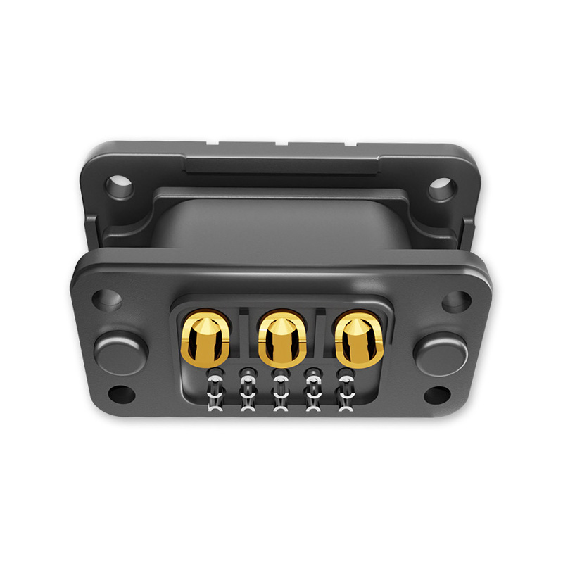
Stackable Energy Storage Connector
Why Stackable Energy Storage Systems Need a Different Connector Design
Energy storage systems are becoming more modular. A homeowner may begin with one battery unit and later add additional modules. A commercial operator may increase storage capacity in stages according to energy demand, site conditions, or investment plans. Industrial systems may use multiple battery cabinets that must be connected quickly during production, installation, commissioning, or maintenance. In each of these cases, the electrical interface must support repeatable assembly while maintaining adequate current-carrying and insulating performance.
Traditional cable connections are often selected because they are familiar and widely available. Nevertheless, a cable-based design can become difficult to manage as the number of battery modules grows. Each module may require positive and negative conductors, protective routing, cable glands, terminal hardware, and additional space for bending radius. The installer must inspect the connection points, position the cables correctly, tighten the hardware, and confirm that the conductors are not under excessive mechanical stress.
External wiring may also affect the visual and physical organization of a storage system. In household applications, users generally expect the equipment to be compact and presentable. In commercial or industrial applications, organized wiring simplifies inspection and can reduce the time required for troubleshooting. A connector positioned directly between stacked modules can eliminate many unnecessary cable paths and create a cleaner, more repeatable installation.
Another challenge is alignment. Battery modules may not be positioned with perfect accuracy during installation. Small deviations can occur because of cabinet tolerances, floor unevenness, module housing dimensions, or the movement required to place one unit on top of another. A rigid connector with little tolerance may require precise visual alignment before the modules can be joined. If the connector is forced into an offset position, the terminals or housing may be damaged. A floating structure is intended to provide controlled compensation during mating, helping the connector engage through guide columns rather than depending entirely on the installer’s line of sight.
For these reasons, a modern stackable connector must do more than conduct electricity. It should assist mechanical alignment, tolerate practical installation conditions, protect conductive parts, resist impact, simplify assembly, and support the safety requirements of direct-current battery systems. The stackable energy storage connector combines these functions in a compact interface designed for modular energy storage applications.
Product Overview
The stackable energy storage connector is a high-current interconnection component for battery modules and energy storage equipment. It is designed for floating blind insertion and may also be supplied in a fixed arrangement depending on the system structure. The connector uses an insulating PA66 housing and gold-plated brass conductive elements. Its published rated-current options include 50A to 70A and 120A to 240A configurations, while the standard electrical description lists a rated voltage of 220V DC.
The connector is installed with an M4 mounting screw. Its floating installation type allows the mating interface to move within a controlled range during assembly. Guide columns help the male and female ends find the correct position without requiring direct visual inspection of the terminal interface. The terminal can retract, which helps reduce the effect of impact or temporary misalignment during connection. The product is intended for applications where battery modules are stacked or placed in close alignment and where minimizing external cables is a priority.
The connector is suitable for household energy storage, energy storage cabinets, industrial energy storage, commercial energy storage, photovoltaic systems, inverters, water-cooling equipment, and other new-energy installations. It can be considered for battery module interfaces, cabinet-to-module connections, internal power distribution, and other locations where a compact, repeatable, high-current connection is required.
| Item | Specification | Application Significance |
| Insulation material | PA66 | Provides a durable insulating housing for the connector assembly |
| Conductor material | Gold-plated brass | Supports conductive performance and corrosion resistance at the contact interface |
| Rated current | 50A–70A; 120A–240A configurations | Allows selection according to battery architecture and load requirements |
| Rated voltage | 220V DC | Suitable for specified direct-current energy storage applications |
| Contact resistance | ≤0.5mΩ | Helps reduce connection losses and localized heating |
| Insulation resistance | >10MΩ at 500V DC | Supports separation between conductive and insulating parts |
| Dielectric strength | 500V AC or 4000V AC, depending on configuration and test requirement | Provides an electrical withstand reference for design verification |
| Mounting screw | M4 | Supports practical mechanical installation |
| Flammability rating | UL94 V-0 | Helps limit flame propagation in the insulating material |
| Operating temperature | -40°C to 125°C | Supports use across a broad range of environmental conditions |
| Installation type | Floating | Permits controlled alignment during blind mating |
Actual current, voltage, dielectric-strength, dimensional, and environmental requirements should always be confirmed against the selected product drawing, test report, and application conditions. Energy storage systems vary significantly in battery chemistry, series-parallel configuration, operating voltage, short-circuit current, enclosure design, and protection strategy. A connector should be selected as part of the complete electrical and mechanical system rather than treated as an isolated component.
Floating Blind Insertion for Modular Battery Assembly
One of the most important features of this product is its floating blind-insertion structure. In a conventional rigid interface, the two halves must be aligned accurately before the contacts can mate. The installer may need to see the connection point clearly, hold the module in a precise position, and make sure that the terminal enters straight. This is not always practical when battery units are stacked inside a cabinet or when the upper module blocks the installer’s view.
The floating structure allows controlled movement of the connector during the mating process. Guide columns assist the male and female ends as they approach each other. Instead of relying solely on visual inspection, the mechanical guidance directs the components toward the correct position. This can make installation more repeatable, particularly when the battery modules are designed with defined stacking locations.
Blind insertion is valuable in several situations. A household battery may be assembled against a wall where the rear connection cannot be observed. A cabinet may have limited access space between modules. A production line may require operators to install connectors quickly without repeatedly checking the terminal position. A service technician may need to replace a module while working in a confined enclosure. In each case, a guided, floating connection can reduce the effort associated with alignment.
The term “blind insertion” does not mean that inspection is unnecessary. Proper installation should still include visual examination of accessible areas, confirmation of complete mating, verification of locking or retention features, and electrical testing. The advantage is that the connector’s mechanical structure helps achieve alignment during the connection process, rather than forcing the installer to depend entirely on direct visibility.
Guide columns also provide an opportunity to separate mechanical alignment from electrical contact. The guide elements begin positioning the connector before the conductive terminals engage. This can reduce the likelihood of side loading, angled insertion, or contact damage. When the modules are fully seated, the electrical interface can reach its intended position within the housing.
Compared with a basic rigid connector, the floating design may offer a more forgiving installation experience. Compared with a cable-and-lug arrangement, it can eliminate several manual steps, including cable routing, lug positioning, and repeated torque checks at multiple external connection points. The result is a more integrated approach to modular battery assembly.
Retractable Terminals and Impact Resistance
Battery modules are heavy components. During stacking, movement can occur as a module is lifted, lowered, adjusted, or removed. A fixed terminal that receives an unexpected impact may experience bending, deformation, or damage to the surrounding housing. The retractable terminal design is intended to help manage this type of installation stress.
When the terminal can retract within its mechanical structure, it may move away from a direct impact instead of remaining completely exposed. This feature can help protect the contact and reduce the consequences of temporary interference during mating. It also complements the floating structure by allowing the connector to accommodate controlled movement in more than one part of the connection process.
Impact resistance is especially relevant in modular systems that are assembled and serviced repeatedly. Residential storage products may be expanded over time. Commercial cabinets may undergo maintenance or module replacement. Manufacturing facilities may perform repeated assembly operations before the equipment reaches the customer. A connector designed with mechanical protection can be better suited to these conditions than an exposed terminal arrangement.
Mechanical protection also contributes to product consistency. If the conductive interface is less likely to be damaged during handling, the connector has a better opportunity to maintain its intended contact pressure and resistance. Of course, impact resistance does not make the product immune to abuse. Excessive force, incorrect alignment, contamination, or use outside the specified mechanical limits can still cause damage. Proper guides, mounting surfaces, and installation procedures remain essential.
The combination of retractable terminals, guide columns, and a floating mounting structure gives the product a functional advantage over simple fixed interfaces. These features are designed around the actual movement of battery modules rather than treating the electrical connection as a separate step after mechanical assembly.
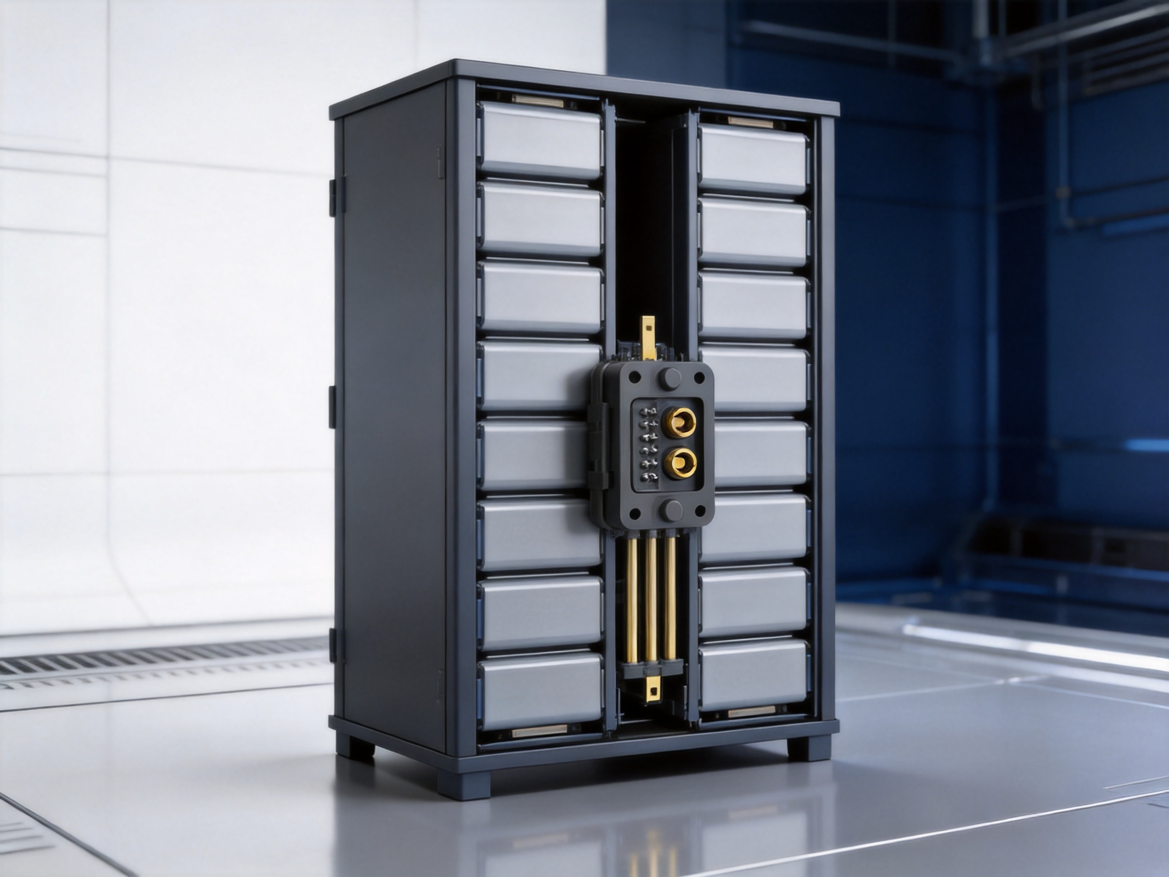
Electrical Performance and Contact Reliability
Electrical efficiency is a central consideration in energy storage systems. Battery current may flow through the connector during charging, discharging, peak-load support, and power conversion. Any unnecessary resistance produces voltage drop and heat. Over time, excessive temperature at a connection can accelerate material aging, affect nearby insulation, and reduce system reliability.
The published contact resistance of the stackable energy storage connector is no more than 0.5 milliohms. A low-resistance interface helps reduce conductive losses when the connector is carrying its intended current. For example, at 70A, a resistance of 0.5 milliohms corresponds to an idealized connection loss of approximately 2.45 watts using the relationship P = I²R. At higher current, the effect increases, which makes contact design, thermal management, current derating, and installation quality important parts of system engineering.
Actual operating temperature depends on more than the nominal resistance. Designers should consider current duration, ambient temperature, enclosure ventilation, adjacent heat sources, conductor size, contact pressure, surface condition, and the number of energized interfaces. The connector’s low-resistance specification provides a design reference, but final thermal verification should be performed in the complete equipment configuration.
Gold plating on the brass conductor is intended to support stable contact performance and resistance to surface oxidation. A plated contact can be beneficial in environments where humidity, storage time, repeated mating, or small amounts of contamination might otherwise affect the contact surface. The plating system, thickness, base material, contact force, and mating cycle requirements should be evaluated together for the intended application.
Brass provides a practical combination of conductivity, mechanical strength, formability, and compatibility with precision terminal production. The conductor must maintain its shape and contact force while also fitting accurately within the insulating housing. Precision stamping, forming, plating, and inspection are therefore important manufacturing steps.
The connector is specified for 220V DC in the available product information. Direct-current interruption and insulation requirements can differ from those of alternating-current equipment. Battery systems may also generate high fault currents, so the connector must be integrated with suitable fuses, contactors, circuit breakers, pre-charge circuits, battery-management systems, and protective enclosures where required. The connector provides an interconnection function; it is not a substitute for the complete protection architecture of an energy storage system.
Insulation, Dielectric Strength, and Material Selection
The connector uses PA66 as its primary insulation material. Polyamide 66 is widely used in electrical and mechanical components because it offers a useful balance of strength, dimensional stability, processing capability, and temperature performance. In a connector housing, the material must support the terminals, preserve creepage and clearance distances, resist mechanical stress, and provide reliable isolation between conductive parts.
The published insulation resistance is greater than 10 megohms at 500V DC. High insulation resistance helps limit leakage between conductive elements and supports the separation required in battery equipment. The product information also lists dielectric-strength values of 500V AC and 4000V AC depending on the specification table or test configuration. Because these values may correspond to different versions, test methods, or customer requirements, the applicable value should be confirmed before design approval.
The UL94 V-0 flammability rating is another important feature for energy storage equipment. A V-0-rated material is evaluated for its ability to limit burning and flame propagation under the applicable test method. In a battery system, the insulating housing is one part of a larger safety design that may include cell spacing, thermal barriers, venting, fuses, monitoring, enclosure construction, and fire-control provisions. A flame-retardant housing can support the overall safety strategy, but it does not eliminate the need for system-level risk assessment.
The operating temperature range is stated as -40°C to 125°C. This broad range can support indoor and outdoor equipment subject to cold starts, elevated cabinet temperatures, seasonal changes, or heat generated by charging and discharging. The continuous current capability at a particular temperature must still be evaluated. Materials, contact resistance, enclosure ventilation, and duty cycle all influence the allowable operating point.
Material selection is most effective when it is linked to actual operating conditions. For example, a connector installed in a climate-controlled residential cabinet may face different demands from one installed in an outdoor photovoltaic storage enclosure. The customer should provide information about humidity, salt exposure, vibration, dust, chemicals, altitude, installation orientation, mating frequency, and expected service life. This information enables the manufacturer to verify the appropriate material, plating, sealing, and mechanical configuration.
Reducing External Cables and Simplifying System Architecture
A major advantage of a stackable connector is the possibility of reducing external cables. In a cable-based system, every additional battery module can add conductors, routing space, support points, bend requirements, and connection hardware. As the system expands, cable management can become a significant part of the cabinet design.
Direct stacking interfaces can place the connection near the natural mechanical relationship between the modules. This can shorten the electrical path and reduce the number of visible conductors. The equipment may become easier to inspect because the connection points follow a consistent, predefined arrangement. A cleaner layout can also help installers distinguish power interfaces from communication wiring, grounding paths, cooling lines, and auxiliary connections.
Reducing cables does not mean removing all wiring from an energy storage system. Battery-management communication, temperature sensing, grounding, auxiliary power, and protective devices may still require dedicated conductors. The benefit is that high-current module-to-module connections can be integrated into the stack structure instead of being routed externally wherever possible.
Fewer external power cables may also reduce opportunities for incorrect routing. Cables that are too tightly bent, inadequately supported, placed near sharp edges, or exposed to heat can create long-term reliability problems. A connector mounted at the intended interface can make the assembly more standardized. Standardization is valuable for both manufacturing and field service because the same connection method can be repeated across multiple modules.
From a product-design perspective, an integrated interface may help reduce cabinet volume. Space previously reserved for cable loops and routing channels can potentially be used more efficiently. Smaller equipment may be easier to install in homes, utility rooms, commercial facilities, or constrained industrial spaces. The actual space saving depends on the housing design, connector dimensions, cable requirements, and safety clearances.
The visual benefit should not be underestimated. Household energy storage is increasingly installed in visible areas such as garages, utility rooms, offices, and small commercial premises. A system with orderly module interfaces and fewer loose cables may be perceived as more professional and easier to maintain. Appearance is not a replacement for engineering quality, but it is an important consideration in modern energy products.
Applications Across the New-Energy Industry
Household Energy Storage
Residential battery systems often use modular units so that customers can select an initial capacity and expand it later. Stackable connectors are suited to this concept because they allow adjacent modules to be connected through a compact interface. The floating structure can simplify positioning when modules are placed in a vertical stack, while the reduced cable requirement can improve the appearance of the installation.
Residential products must also be approachable for installers. A system that requires numerous visible cables and complicated terminal access may take longer to commission. A guided connector can support a more repeatable installation process, provided the product is used with clear mechanical and electrical instructions. The connector can be considered for indoor storage cabinets, wall-adjacent battery towers, and modular backup power systems.
Commercial Energy Storage
Commercial facilities may require greater capacity than a single residential unit can provide. Modular battery cabinets allow capacity to be expanded according to building loads, solar generation, peak-shaving objectives, or backup requirements. In these systems, connection consistency is especially important because a large number of modules or cabinets may be installed and serviced over many years.
A stackable connector can support orderly assembly and reduce the time spent managing external power cables. It may also make it easier to remove a module for inspection or replacement. Commercial systems should include appropriate isolation procedures, lockout and tagout practices, pre-charge arrangements, monitoring, and fault protection. The connector should be selected according to the continuous current, peak current, voltage, temperature, and environmental conditions of the commercial installation.
Industrial Energy Storage
Industrial storage equipment may operate under demanding electrical and mechanical conditions. Systems can be exposed to vibration, dust, elevated temperatures, frequent load cycles, and long operating hours. A connector with a mechanically guided interface and robust insulating housing may help support industrial equipment designs where repeatable assembly and high-current reliability are essential.
Industrial users may also benefit from customized conductor geometry, mounting arrangements, cable interfaces, or current ratings. The manufacturer’s experience in flexible copper connections and special-shaped conductive components can support the development of interfaces that fit the available space and current path. Engineering review should include thermal rise, vibration resistance, terminal retention, enclosure protection, and maintenance procedures.
Photovoltaic Systems and Inverters
Solar photovoltaic systems increasingly use battery storage to shift energy, improve self-consumption, provide backup power, or support grid services. The battery modules are connected to inverters and power-conversion equipment that may operate across significant voltage and current ranges. A stackable connector can be used within the battery assembly or at a suitable internal interface, while the complete system continues to require correctly rated DC disconnects, fuses, contactors, and cabling.
The connector’s compact form can help designers organize the battery side of the system. Its temperature range may also be useful in equipment where heat is generated by power conversion. However, photovoltaic installations may be exposed to humidity, condensation, ultraviolet radiation, and outdoor contaminants. The connector’s enclosure and installation environment must therefore be assessed carefully, and additional protection may be necessary.
Water-Cooling and Thermal-Management Equipment
High-capacity batteries often require thermal management. Water-cooling plates, pumps, hoses, manifolds, and sensors may be installed near high-current electrical interfaces. A compact connector can help preserve space in a system where cooling channels and power paths compete for available volume.
Electrical and cooling components must be kept appropriately separated. Designers should evaluate leakage risks, condensation, fluid compatibility, service access, and the consequences of a cooling-system failure. The connector is suitable for consideration in water-cooled storage equipment when its environmental rating and installation arrangement are verified for the specific design.
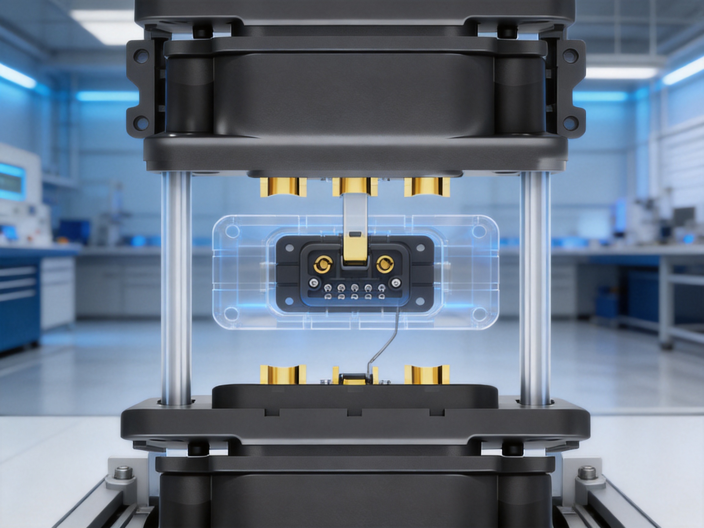
Manufacturing Strengths Behind the Product
The performance of an energy storage connector depends on more than its visible housing and terminal shape. Consistent performance requires controlled processes across material preparation, precision forming, surface treatment, plastic molding, assembly, inspection, and testing. Zhejiang Zhongyan New Energy Co., Ltd. focuses on conductive components and precision connection solutions, with technical experience in high-voltage copper foil soft connections, special-shaped flexible connections, battery soft connections, and other new-energy parts.
The company was established in 2022 and has developed its capabilities around new-energy precision components. Its engineering team brings experience in product design, research and development, production, and application support. The company reports that it uses independently developed polymer diffusion welding and laser technology patents to produce low-resistance, high-reliability connection products. These capabilities are relevant to the broader development of battery connection systems because energy storage products require both electrical performance and mechanical integration.
Engineering and Product Development
Product development begins with understanding the customer’s system. Battery voltage, current profile, module dimensions, stacking direction, available installation space, mounting points, environmental conditions, and maintenance requirements all affect connector design. The company’s engineering approach can be used to develop standard or customized configurations based on these parameters.
Computer-aided design and dimensional analysis help define the housing, guide columns, terminal geometry, mounting structure, and clearance distances. Prototypes can then be evaluated for mating force, alignment tolerance, terminal movement, insertion depth, retention, and mechanical interference. Early testing is important because a connector that performs well electrically may still be difficult to install if the mechanical interface is not properly designed.
Special-shaped conductive components are often required in compact energy equipment. A straight terminal may not provide the most efficient current path or fit the available space. Experience in forming and manufacturing special-shaped copper and brass components can help the manufacturer adapt the connector to different battery layouts. Customization may involve terminal orientation, mounting position, conductor geometry, plating requirements, housing color, keying, or interface dimensions.
Polymer Diffusion Welding
Polymer diffusion welding is identified by the company as one of its independently developed technologies. In relevant conductive-component applications, advanced joining processes can help create stable, low-resistance interfaces between conductive materials or assembled elements. The process must be controlled carefully through parameters such as surface preparation, pressure, temperature, energy input, alignment, and post-weld inspection.
A reliable joining process is valuable because hidden internal joints can influence the performance of the finished component. Poorly controlled joints may increase resistance, create local heating, reduce mechanical strength, or become unstable under thermal cycling. By combining process development with electrical and mechanical verification, the manufacturer can work toward consistent connection quality.
The specific welding process used for a particular connector or conductive assembly should be confirmed through the applicable manufacturing documentation. Customers with demanding applications may request process capability data, sample approval, cross-sectional analysis, resistance testing, tensile testing, or traceability records.
Laser Technology
Laser technology can support precise manufacturing and joining of conductive components. It may be used for welding, cutting, marking, or localized processing where accuracy and repeatability are required. Laser processing can help reduce mechanical distortion and create controlled joining areas, although the result depends on material type, thickness, surface condition, equipment calibration, and process parameters.
For energy storage components, precision is important because terminals and conductive parts must fit within compact insulating structures. Laser processing can support complex geometries and fine features that may be difficult to produce with conventional methods alone. The manufacturer’s laser capabilities can therefore contribute to the development of custom battery connectors, copper foil soft connections, and other precision conductive components.
Material and Surface Treatment Control
The stackable connector uses gold-plated brass contacts. Material control includes verifying the base metal, dimensions, hardness, forming characteristics, and surface condition. Plating control may include checking adhesion, coverage, thickness, appearance, and resistance to the intended environmental exposure. These checks help ensure that the contact surface performs consistently from one production batch to another.
The PA66 housing also requires careful control. Injection-molding parameters affect dimensions, warpage, weld lines, surface quality, and the fit between the housing and terminals. The material grade, flame-retardant characteristics, color, moisture condition, and molding temperature can influence final performance. A stable process is essential for maintaining guide-column alignment and the clearances needed for insulation.
Assembly and Quality Management
Connector assembly may include terminal insertion, retention verification, floating-mechanism installation, spring or retractable-terminal placement, screw installation, and final inspection. Each step should be supported by defined work instructions and suitable fixtures. Automated or semi-automated inspection can help identify missing components, incorrect orientation, incomplete insertion, or dimensional deviations.
Quality management should cover incoming materials, in-process operations, final testing, packaging, and shipment. Depending on customer requirements, inspection may include contact resistance, insulation resistance, dielectric withstand, insertion and withdrawal force, terminal retention, visual appearance, dimensional accuracy, temperature exposure, vibration, and mechanical impact. The exact test plan should reflect the product drawing and intended use.
Traceability is particularly valuable for battery-related components. Recording material batches, plating lots, molding conditions, assembly dates, inspection results, and shipment information can help identify the source of a problem if a field issue occurs. It can also support continuous improvement and customer audits.
Advantages Over Conventional and Competing Connection Methods
Compared with External Cable Assemblies
The most direct comparison is with external cable assemblies using lugs or threaded terminals. Cable assemblies remain useful and may be required in certain system layouts, but they normally require additional routing space and manual fastening. The stackable connector integrates the interface with the module arrangement and can reduce the number of high-current cables between stacked units.
The connector also reduces dependence on cable bending radius and external strain relief at the module-to-module interface. Its guided mating structure can make assembly more repeatable than manually positioning flexible conductors. For product manufacturers, this may support a more standardized battery platform and simplify the customer installation process.
Compared with Rigid Fixed Connectors
A rigid connector can offer a simple and strong interface when all mounting tolerances are tightly controlled. However, a fixed connector may be less forgiving when the battery modules are slightly offset. The floating design provides controlled movement and guided alignment, making it more suitable for stacked assemblies where module positioning varies within a practical tolerance range.
The retractable terminal further distinguishes the product from a simple exposed fixed contact. It is intended to help reduce the effect of impact during assembly and maintenance. This mechanical behavior can contribute to serviceability and reduce the risk of damage caused by imperfect insertion.
Compared with Basic Unprotected Terminals
Basic terminals may require separate covers, insulators, mounting hardware, and alignment features. The stackable connector combines the conductive interface with a PA66 insulating housing and mechanical guiding structure. The UL94 V-0 housing specification and high insulation resistance provide useful references for equipment designers who need an enclosed and protected interface.
Compared with Generic Low-Cost Connectors
Generic connectors may appear attractive on purchase price, but selection based only on unit cost can overlook contact resistance, plating quality, dimensional consistency, mating reliability, thermal behavior, and after-sales engineering support. Energy storage systems operate with stored energy and potentially high fault current, so the connection component must be evaluated over its intended service life.
A manufacturer specializing in new-energy conductive components can provide more relevant support than a general-purpose connector supplier. Experience with battery soft connections, copper foil components, laser processing, and customer-specific development allows the supplier to consider the connector as part of a complete current path. This system-oriented perspective can be valuable when the customer needs customized geometry, current capacity, mounting details, or integration with a battery module.
Integration with Battery Management and Protection Systems
The stackable energy storage connector carries power, but safe energy storage operation depends on coordinated electrical controls. Battery-management systems monitor cell voltage, temperature, state of charge, state of health, and fault conditions. Contactors and pre-charge circuits control the connection between the battery and the inverter or load. Fuses or circuit breakers provide overcurrent protection. Grounding and insulation-monitoring systems may be required according to the equipment design and applicable standards.
When integrating the connector, the designer should determine whether it is energized during mating or unmating. If live insertion is not specifically permitted by the product design, the system should be de-energized before connection or service. The connector should not be used to interrupt current unless it has been specifically rated for that function. DC arcs can be persistent and hazardous, particularly at higher voltage and current.
Keying and polarity control are also important. Positive and negative interfaces should be clearly identified and mechanically arranged to prevent incorrect installation. If multiple connector types or positions are used within a cabinet, physical keying, labels, color coding, and electrical verification can reduce assembly errors.
Service personnel should be able to confirm complete mating. Depending on the design, this may involve a visible position indicator, a defined seating position, a locking feature, a specified insertion force, or an electrical continuity check. The floating structure assists alignment but should not be interpreted as permission to operate the connector outside its specified insertion and retention conditions.
Design and Installation Recommendations
Before selecting a connector, the equipment manufacturer should establish the maximum continuous current, short-duration peak current, nominal voltage, maximum working voltage, temperature range, expected mating cycles, mechanical tolerances, and environmental exposure. The rated current should be selected according to the actual thermal conditions rather than only the nominal battery capacity.
The mounting structure should provide sufficient strength and alignment. M4 mounting screws should be tightened according to the approved installation procedure, using the specified hardware and torque. Over-tightening may distort the housing or restrict floating movement, while insufficient tightening may allow movement that places stress on the terminals.
The mating modules should include suitable mechanical guides so that the connector is not used to carry the full weight of a battery module. The connector should guide and complete the electrical interface, but the battery housing or cabinet structure should support the mechanical load. This approach can protect the connector from excessive shear, bending, or impact.
Clearance should be provided around the floating mechanism and retractable terminal. Foreign objects, cable ties, insulation fragments, metal particles, and excessive sealant should not obstruct movement. The contact area should be kept clean and protected from unnecessary handling. If the connector is installed in a dusty, humid, or corrosive environment, the overall enclosure and sealing strategy should be reviewed.
During commissioning, installers should check housing integrity, terminal position, module alignment, screw installation, polarity, electrical continuity, insulation resistance, and the absence of unintended short circuits. Thermal inspection under representative load can help verify that the connection remains within the expected temperature range.
Maintenance procedures should include visual inspection for discoloration, melting, cracking, looseness, corrosion, contamination, and abnormal heating. If a connector has experienced a severe impact, forced insertion, overcurrent event, or overheating, it should be evaluated before being returned to service. Replacement intervals should be based on application conditions, mating cycles, inspection results, and manufacturer guidance.
Customization and OEM Support
Energy storage equipment is not standardized around one mechanical format. Battery module dimensions, stacking direction, cabinet width, terminal position, cable exit direction, cooling layout, and protection strategy vary among manufacturers. For this reason, an off-the-shelf connector may not always fit the required system architecture.
Zhejiang Zhongyan New Energy Co., Ltd. provides customized manufacturing support for conductive components and precision connection products. Possible customization areas may include current rating, conductor shape, plating specification, housing geometry, mounting position, guide-column arrangement, floating range, terminal orientation, polarity marking, and assembly method. The available options depend on engineering review and production capability.
OEM development should begin with a complete technical brief. Useful information includes mechanical drawings, battery voltage, current profile, target operating temperature, mating direction, available space, expected service life, environmental conditions, applicable standards, and testing requirements. Three-dimensional models, sample modules, or prototype cabinets can improve design accuracy and reduce development cycles.
Prototype evaluation should examine both electrical and mechanical performance. Electrical tests may include contact resistance, insulation resistance, dielectric withstand, temperature rise, and current cycling. Mechanical tests may include insertion force, withdrawal force, terminal retention, alignment tolerance, vibration, impact, and repeated mating. Environmental tests may include temperature cycling, humidity, corrosion exposure, and contamination resistance when relevant to the application.
Customized development is most effective when the customer and manufacturer review the entire current path. The connector may need to work with copper busbars, flexible copper foil connections, battery terminals, contactors, fuses, and inverter interfaces. A supplier with experience in these adjacent components can identify potential interference, heat concentration, assembly constraints, and material compatibility issues earlier in the design process.
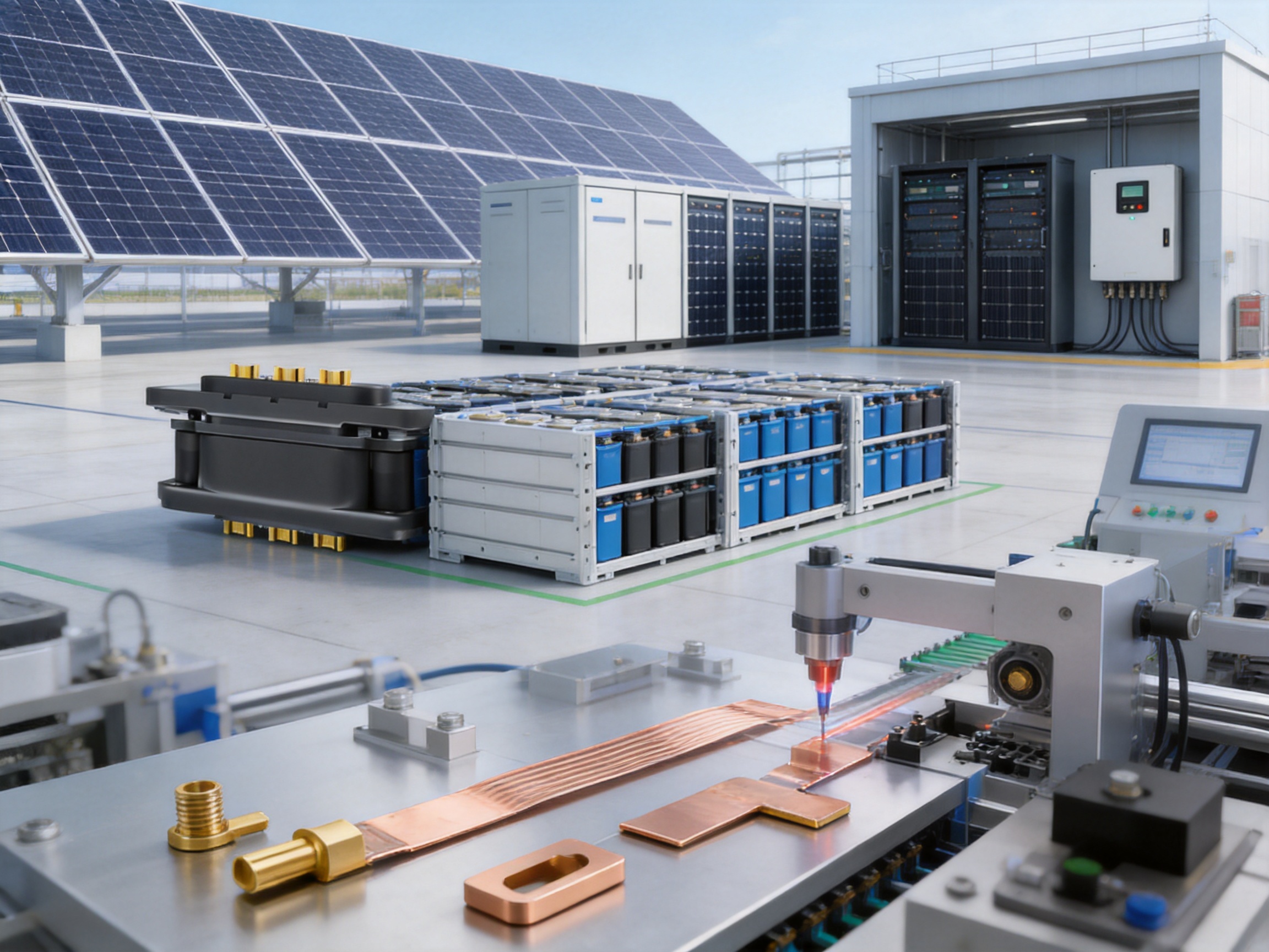
Company Capabilities in New-Energy Conductive Components
Zhejiang Zhongyan New Energy Co., Ltd. is a high-tech enterprise focused on the research and manufacturing of new-energy conductive components. Its product and technology scope includes high-voltage electrical copper foil soft connections, special-shaped soft connections, battery soft connections, and precision connection components for power transmission and distribution, electric vehicles, rail transit, communications, and energy storage.
The company brings together experienced engineers and technical personnel and is equipped with professional manufacturing and testing equipment. Its capabilities cover product design, research and development, production, quality management, and customer-specific solution development. This combination is important because modern energy storage products require more than a standard catalog part. They require interfaces that fit the battery structure, carry the required current, tolerate thermal and mechanical stress, and can be manufactured consistently.
The company reports that it has become a core supplier for leading enterprises, including BYD, CATL, and Jaguar. Such customer experience indicates exposure to demanding requirements in new-energy and automotive-related applications. While every project must still be evaluated individually, experience with high-volume or high-reliability customers can support disciplined engineering, process control, and quality expectations.
The company is also developing an innovation system covering materials science, precision machining, testing, and verification. This broader capability supports the development of integrated battery connection systems. By understanding both battery cells and conductive interconnections, the company is working toward customized battery solutions that combine high performance, integration, and reliability.
Its strategic direction includes expansion into lithium battery manufacturing and the integrated design of battery cells and connection systems. This direction is relevant to energy storage customers because the best connection solution is often determined during the early battery-pack design stage. When the cell arrangement, busbar path, soft connection, terminal structure, and connector interface are designed together, the result can be more compact and easier to manufacture than a system assembled from unrelated components.
Contribution to Cleaner and More Efficient Energy Infrastructure
Energy storage enables renewable electricity to be used more flexibly. Batteries can store solar energy during periods of high generation and release it when demand increases. They can provide backup power, support peak shaving, improve self-consumption, and help stabilize electrical systems. Reliable connectors are small components, but they are essential to the safe and efficient operation of these larger systems.
The stackable connector supports this transition by helping energy storage manufacturers build modular products. Modular products can be transported, installed, expanded, and serviced more easily than a single oversized battery assembly. A guided, compact interface can improve the practicality of modular design while reducing the visual and physical burden of external high-current cables.
Lower contact resistance can help reduce energy losses at the connection point. Improved mechanical protection can reduce the chance of damage during installation. Insulating materials with a UL94 V-0 rating can contribute to equipment safety planning. Together, these characteristics support the broader objective of developing storage systems that are dependable, serviceable, and suitable for wider adoption.
Environmental responsibility also includes manufacturing efficiency and product life. A connector that is stable, repairable, and consistently produced can help reduce premature replacements. Efficient production processes, controlled material usage, and integrated product design may further support the sustainability goals of the energy storage industry.
Selection Checklist for System Designers and Buyers
When evaluating the stackable energy storage connector, buyers should first confirm the electrical requirements. The nominal and maximum DC voltage, continuous current, peak current, duty cycle, allowable voltage drop, and fault-current conditions should be documented. The available current configurations include 50A–70A and 120A–240A ranges, but the appropriate option depends on the complete thermal and electrical design.
The mechanical interface should then be reviewed. Important factors include module dimensions, connector centerline, mating direction, floating range, guide-column position, mounting-hole spacing, M4 screw access, terminal travel, module weight, and support structure. A sample assembly or three-dimensional model can help verify that the connector will not be overloaded during stacking.
Environmental conditions should also be defined. The stated operating temperature range is -40°C to 125°C, but designers should consider humidity, condensation, dust, salt spray, vibration, shock, chemical exposure, altitude, and outdoor installation. If the connector is installed inside a protected cabinet, the cabinet rating and internal thermal conditions must be considered together with the connector specification.
Finally, the buyer should confirm documentation and quality requirements. These may include drawings, material certificates, plating information, inspection standards, test reports, sample approval, production traceability, packaging specifications, and change-control procedures. A supplier’s engineering responsiveness and ability to support customization may be as important as the initial product price.
Q&A: Stackable Energy Storage Connector
What is a stackable energy storage connector?
It is a high-current electrical interface designed to connect stacked or closely aligned battery modules and energy storage units. It replaces or reduces certain external cable connections by placing the power interface directly at the module-to-module connection point.
What does floating blind insertion mean?
Floating blind insertion means that the connector can accommodate controlled movement during mating, while guide columns help the male and female ends align. The installer does not need a direct view of the terminal interface throughout the insertion process, although correct installation and final inspection remain necessary.
What current ratings are available?
The product information lists 50A–70A and 120A–240A configurations. The correct selection depends on the battery system’s continuous current, peak current, thermal conditions, and safety margins. The selected rating should be confirmed with the manufacturer before production approval.
What is the rated voltage?
The published rated voltage is 220V DC. The actual system voltage, maximum working voltage, insulation coordination, and applicable test requirements should be reviewed for each project.
What materials are used?
The insulation is specified as PA66, and the conductor is brass with gold plating. PA66 provides a durable insulating housing, while gold-plated brass is intended to provide a stable and corrosion-resistant contact interface when manufactured and used according to the approved specification.
What is the contact resistance?
The stated contact resistance is no more than 0.5 milliohms. Actual performance depends on terminal force, surface condition, insertion completeness, current level, temperature, and manufacturing consistency. Thermal verification in the final equipment is recommended.
Why is the terminal retractable?
A retractable terminal can move within the connector structure during installation and help reduce the effect of impact or temporary misalignment. It is designed to protect the interface and support smoother mating, but it should not be forced or used outside its specified mechanical limits.
Is the connector suitable for residential battery systems?
Yes. It is intended for household energy storage as well as energy storage cabinets, commercial systems, industrial storage, photovoltaic equipment, inverters, and other new-energy applications. The final suitability depends on voltage, current, enclosure, temperature, mounting, and protection requirements.
Can the connector be used in photovoltaic or inverter equipment?
It may be used in suitable internal or module interfaces within photovoltaic storage and inverter-related equipment. The designer must confirm the DC voltage, current, environmental exposure, thermal conditions, and required protection devices before use.
Does the connector eliminate all battery cables?
No. It can reduce or replace certain high-current external cables between stacked modules, but communication wiring, grounding, sensing circuits, protective devices, auxiliary power, and other system connections may still be required.
Can the product be customized?
Customization may be available for conductor geometry, mounting arrangement, current configuration, housing design, guide features, terminal orientation, plating, and other requirements. Customers should provide mechanical, electrical, environmental, and production information for an engineering assessment.
What manufacturing experience supports the product?
The manufacturer specializes in new-energy conductive components, including copper foil soft connections, battery soft connections, special-shaped soft connections, and precision electrical components. It also reports capabilities involving polymer diffusion welding, laser technology, precision machining, testing, and verification.
What should be checked during installation?
Installers should check the mounting screws, module alignment, connector seating, polarity, terminal condition, housing integrity, insulation, continuity, and absence of short circuits. The system should be de-energized unless the product is specifically approved for live mating, and the connector should not be used to interrupt current unless rated for that purpose.
How should the connector be maintained?
Maintenance should include inspection for looseness, overheating, discoloration, cracking, deformation, corrosion, contamination, and incomplete mating. A connector exposed to severe impact, forced insertion, or an overcurrent event should be assessed before continued service.
Conclusion
The stackable energy storage connector provides an integrated alternative to complicated external cable arrangements in modular battery systems. Its floating blind-insertion structure, guide columns, retractable terminal, impact-resistant design, low contact-resistance specification, PA66 insulation, gold-plated brass conductor, and UL94 V-0 material rating address several practical requirements of modern energy storage equipment.
Its primary value lies in the combination of electrical and mechanical functions. The connector is not merely a current-carrying terminal. It is designed to help modules align, connect, and remain organized within a stacked architecture. By reducing unnecessary external cables, it can support cleaner equipment layouts, simpler installation, improved service access, and more flexible capacity expansion.
The manufacturing capabilities of Zhejiang Zhongyan New Energy Co., Ltd. strengthen the product’s application potential. Experience in battery soft connections, copper foil components, special-shaped conductive parts, polymer diffusion welding, laser technology, precision manufacturing, and testing provides a foundation for standard and customized energy storage solutions. The company’s broader focus on battery cells and connection systems also supports integrated product development.
For system designers, the connector should be evaluated as part of the complete battery architecture. Current, voltage, temperature, mechanical tolerance, protection, insulation coordination, enclosure conditions, and service requirements must all be confirmed. With appropriate engineering verification and installation practice, a stackable connector can help energy storage manufacturers create systems that are safer, more compact, easier to assemble, and better prepared for the continued expansion of renewable energy.
References
1. Product specification information for the stackable energy storage connector, including electrical, mechanical, material, and environmental parameters.
2. Company technical information concerning new-energy conductive components, battery soft connections, copper foil soft connections, and special-shaped flexible connections.
3. IEC 60664-1, Insulation Coordination for Equipment within Low-Voltage Systems.
4. IEC 60512, Connectors for Electronic Equipment—Tests and Measurements.
5. UL 94, Tests for Flammability of Plastic Materials for Parts in Devices and Appliances.
6. General engineering principles for battery energy storage system design, DC protection, thermal management, insulation, and maintenance.
7. Technical literature on contact resistance, current-carrying capacity, terminal plating, electrical connector reliability, and modular battery-pack integration.
8. Manufacturer drawings, sample test reports, and project-specific validation documents to be confirmed for the selected connector configuration.
Product: Stackable Energy Storage Connector

Driven by the development of new energy and aiming for "zero carbon".
Copyright © Zhejiang Zhongyan New Energy Co., Ltd. All Rights Reserved.
