 English
 Español

12.8V 200Ah LiFePO4 Battery: High-Capacity Energy Storage for Demanding Applications
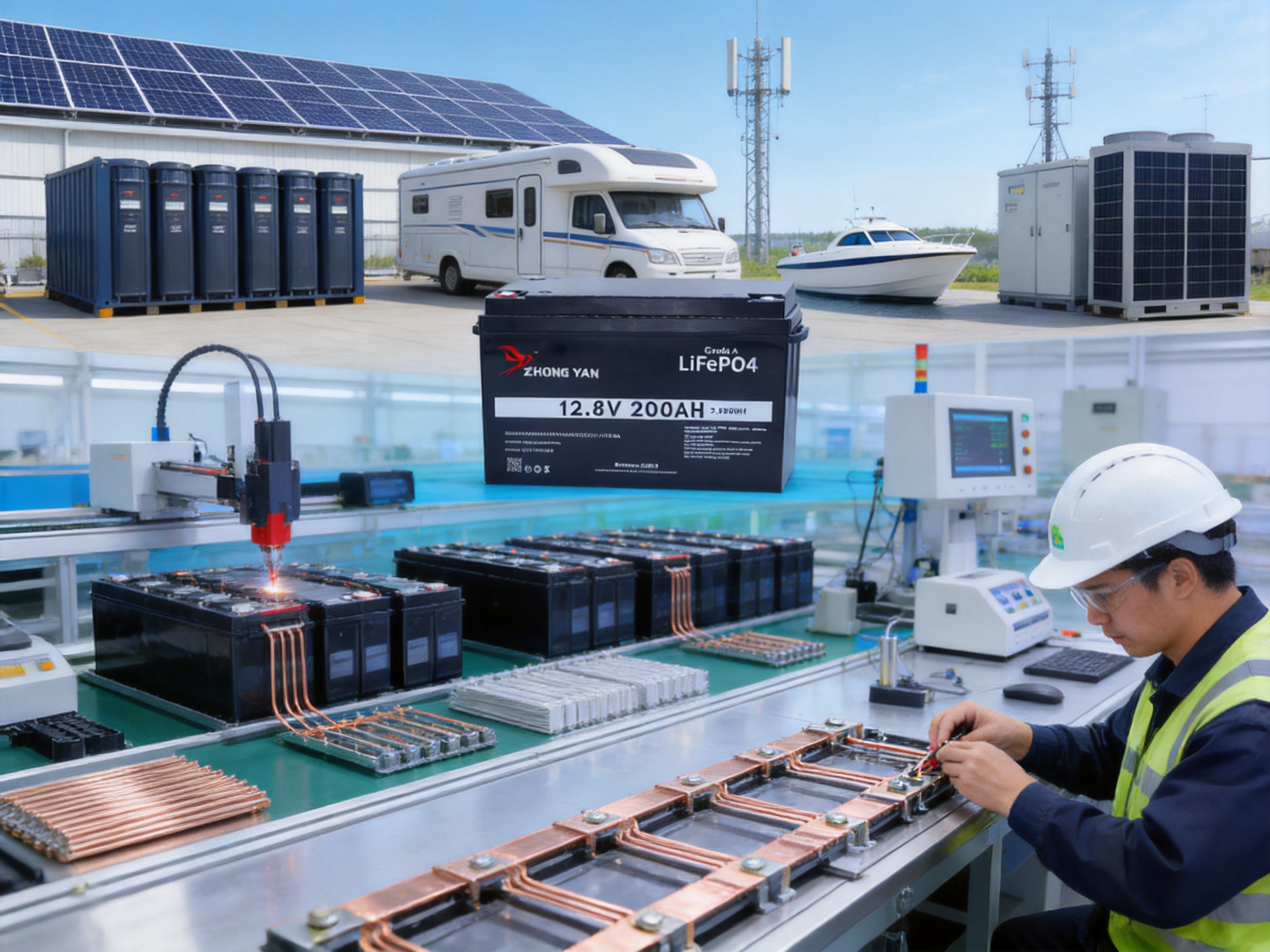
A dependable battery is the foundation of any off-grid, mobile, marine, backup-power, or renewable-energy system. As electrical loads become more demanding and users expect longer operating periods, traditional lead-acid batteries are increasingly limited by their weight, maintenance requirements, short service life, and restricted usable capacity. A 12.8V 200Ah lithium iron phosphate battery provides a practical alternative by combining high usable energy, strong output capability, long cycle life, integrated battery management, and a compact enclosure.
This battery is designed around lithium iron phosphate technology, commonly known as LiFePO4 or LFP. With a nominal voltage of 12.8V and a rated capacity of 200Ah, it provides approximately 2,560Wh of nominal stored energy. Its 4S2P cell arrangement uses eight 3.2V, 100Ah prismatic cells: four cells connected in series establish the battery voltage, while two parallel cell strings provide the 200Ah capacity.
The result is a high-capacity battery intended for applications that require stable voltage, reliable daily cycling, strong peak performance, and reduced maintenance. A programmable 200A smart battery management system with Bluetooth monitoring adds protection and visibility, allowing users to check operating conditions through a compatible mobile application.
Beyond the battery itself, the manufacturing background behind this product is important. Zhejiang Zhongyan New Energy Co., Ltd. specializes in new-energy conductive components, battery soft connections, high-voltage copper foil flexible connections, special-shaped conductive links, and precision connection systems. Its experience in electrical conductivity, low-resistance connections, laser processing, polymer diffusion welding, testing, and quality control supports the development of battery packs that require both electrochemical performance and highly reliable internal current paths.
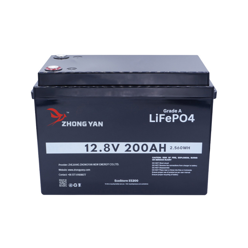
EleStore 200Ah 12.8V LiFePO4 Battery -(EVE Cells) & (Bluetooth BMS -JBD)
What Makes a 12.8V 200Ah LiFePO4 Battery Different?
A battery’s nominal voltage and capacity describe only part of its performance. The chemistry, cell arrangement, battery management system, enclosure, thermal behavior, connection design, and production consistency all influence real-world reliability.
LiFePO4 chemistry is particularly suitable for stationary and mobile energy storage because it offers strong thermal stability and a lower risk of thermal runaway than many conventional lithium-ion chemistries. LFP batteries also maintain a relatively stable discharge voltage over much of their operating range. This helps inverters, DC appliances, communication equipment, and other loads operate consistently.
The 12.8V format is compatible with a wide range of systems originally designed around 12V lead-acid batteries. However, the lithium battery provides a higher usable percentage of its rated capacity. In practical terms, a 200Ah LFP battery can generally deliver more useful energy before recharge than a lead-acid battery with the same nominal amp-hour rating, provided that the system is correctly configured and the battery is operated within its specified limits.
The 2,560Wh nominal energy figure is calculated as follows:
Nominal voltage × rated capacity = nominal energy
12.8V × 200Ah = 2,560Wh
Actual available energy depends on discharge current, temperature, inverter efficiency, battery-management settings, cabling, cut-off thresholds, and the condition of the cells. For this reason, nominal energy should be used for system planning rather than treated as an exact amount of energy available at every load.
Stable Voltage for Sensitive Loads
LiFePO4 batteries typically maintain a stable voltage profile during discharge. This is useful for equipment such as communication systems, portable refrigeration, lighting, monitoring systems, electronic controls, and inverters. A stable voltage can help reduce the frequency of low-voltage shutdowns compared with some lead-acid systems that experience a more pronounced voltage decline under load.
High Usable Capacity
The battery is specified for operation at up to 80% depth of discharge for its stated cycle-life rating. Using a battery within a moderate depth-of-discharge range helps balance energy availability and long-term service life. Users who do not need the full capacity every day may obtain an even more conservative operating profile, while systems with carefully managed charging and discharging can take advantage of the battery’s substantial energy reserve.
Reduced Maintenance
Unlike flooded lead-acid batteries, the enclosed LFP battery does not require electrolyte checks, watering, or routine acid maintenance. It does not produce the same type of gassing associated with flooded batteries during normal operation. Nevertheless, correct installation remains essential. The battery should be mounted securely, protected from direct mechanical damage, connected with correctly sized cables, and operated with a charger or inverter profile suitable for LiFePO4 chemistry.
Core Product Specifications
The following table summarizes the principal specifications supplied for this battery model.
| Item | Specification |
|---|---|
| Battery chemistry | Lithium iron phosphate, LiFePO4 |
| Nominal voltage | 12.8V |
| Rated capacity | 200Ah |
| Nominal energy | 2,560Wh |
| Cell configuration | 4S2P |
| Cell type | Grade A 3.2V 100Ah LFP prismatic cells |
| BMS | Programmable 200A smart BMS |
| Continuous charge current | 200A maximum |
| Continuous discharge current | 200A maximum |
| Peak discharge rate | 760A plus or minus 120A for approximately 1.5 seconds |
| Charging method | Constant current/constant voltage |
| Charging cut-off voltage | 14.8V plus or minus 0.2V |
| Discharge cut-off voltage | 9.0V plus or minus 0.2V |
| Charging temperature | -10°C to 65°C |
| Discharging temperature | -20°C to 75°C |
| Enclosure | ABS |
| Ingress protection | IP67 |
| Terminal type | M8 input and output ports |
| Dimensions | 490 × 170 × 250mm |
| Weight | Approximately 19.5kg |
| Connectivity | Unlimited parallel connection and up to four batteries in series |
| Certifications listed | IEC62619, UL1642A, UN38.3, and RoHS |
| Warranty | Five-year full replacement warranty |
Specifications can vary by production batch or configuration. The supplied product information includes references to both 100Ah and 200Ah descriptions in different sections. The detailed specification identifies the product as a 200Ah battery using a 4S2P arrangement of 100Ah cells. Buyers should confirm the exact nameplate, cell configuration, BMS rating, dimensions, and certification documentation for the shipment being ordered.
Grade A Prismatic Cell Architecture
The battery uses prismatic LFP cells rather than small cylindrical cells. Prismatic cells can simplify pack assembly by reducing the number of individual interconnections and allowing a compact, structured enclosure. The stated design uses Grade A 3.2V, 100Ah cells, arranged in four series groups and two parallel strings.
Cell quality directly affects battery consistency. Cells with closely matched voltage, capacity, internal resistance, and self-discharge behavior are easier for the BMS to manage. They also reduce the risk that one cell group will reach its upper or lower voltage limit significantly earlier than the others.
A professional battery assembly process should therefore include incoming cell inspection, electrical testing, grading, matching, insulation, busbar or flexible-link installation, torque control, BMS wiring verification, and final pack testing. These steps are particularly important in a 4S2P battery because the parallel groups must share current evenly and the series groups must remain balanced during both charging and discharging.
Benefits of the 4S2P Configuration
Four cells in series produce the basic 12.8V nominal architecture. Two parallel strings of those four-cell groups double the capacity from 100Ah to 200Ah. This configuration supports high current while maintaining a practical 12V-class system voltage.
The parallel structure also distributes current across multiple cells. Under a 200A continuous load, the idealized current contribution is shared across the two parallel strings, although actual sharing depends on resistance, busbar layout, temperature, cell matching, and connection quality. Proper design of the internal conductive paths is therefore essential.
This is an area where the manufacturer’s background in conductive components can provide a meaningful engineering advantage. Low-resistance flexible connections and carefully manufactured current paths can help reduce localized heating, voltage drop, and mechanical stress. Battery connections must be electrically efficient and mechanically durable because they experience repeated thermal expansion and contraction during charge and discharge cycles.
200A Smart Battery Management System
The integrated smart BMS is one of the most important features of the battery. A BMS supervises the individual series groups, controls charge and discharge protection, monitors temperature, and disconnects the pack when unsafe conditions are detected.
The specified 200A programmable BMS is designed to match the battery’s high-current capability. It provides protection against overcharge, over-discharge, over-current, over-temperature, and short circuit conditions. The BMS also supports Bluetooth monitoring through the EcoWatt Energy Connect application, allowing users to view selected battery information from a compatible mobile device.
Overcharge Protection
During charging, the BMS monitors the voltage of each cell group. If one group reaches an excessive voltage, the system can interrupt charging to prevent continued overcharging. The stated charging cut-off voltage is approximately 14.8V, with a tolerance of plus or minus 0.2V, although the charger and BMS settings should always be checked together before installation.
Over-Discharge Protection
Over-discharge can damage lithium cells and reduce service life. The BMS monitors pack and cell-group voltage and disconnects the load when the battery reaches its programmed lower limit. The listed discharge cut-off voltage is approximately 9.0V, with a tolerance of plus or minus 0.2V. System designers should avoid intentionally driving the battery to the protection threshold on a routine basis.
Over-Current and Short-Circuit Protection
High-current loads such as inverters, motors, compressors, and winches can create substantial startup surges. The BMS helps protect the cells and internal conductors when current exceeds the programmed limit or a short circuit occurs. However, BMS protection does not replace external fuses, disconnects, circuit breakers, or appropriately rated cables. These components remain necessary for safe system design.
Temperature Monitoring
Temperature limits are central to lithium battery safety. The stated charging range is -10°C to 65°C, while the stated discharge range is -20°C to 75°C. The specifications also identify charging temperature protection above approximately 65°C and discharge temperature protection above approximately 75°C.
Although the listed operating ranges are broad, users should avoid treating the maximum values as ideal operating targets. Moderate temperatures generally support better performance and longer service life. Charging below freezing is particularly important to control in lithium batteries, and the installation should ensure that the battery does not fall outside the permitted charging range.
Bluetooth Monitoring
Bluetooth monitoring gives users access to operational information without opening the enclosure. Depending on the application and BMS interface, information may include battery voltage, current, state of charge, cell-group voltage, temperature, protection status, charge and discharge history, and alarm conditions.
Remote visibility is valuable in solar systems, recreational vehicles, marine installations, telecom equipment, and backup power systems. Instead of waiting for a low-voltage event, an operator can review the battery condition and identify abnormal readings earlier.
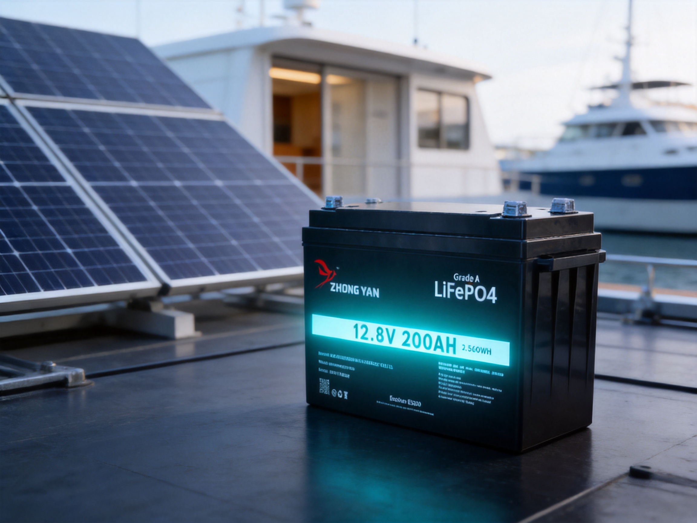
Performance Advantages Compared with Lead-Acid Batteries
The main competitor for a 12V-class LFP battery is often not another lithium battery but a lead-acid battery. Lead-acid technology remains widely used because it is familiar and relatively inexpensive at the time of purchase. However, the total ownership cost can be higher when the battery is cycled frequently.
More Usable Energy
A lead-acid battery generally delivers its best service life when it is not deeply discharged. Although a lead-acid battery may be labeled with the same amp-hour capacity, using a large portion of that capacity repeatedly can shorten its life. LFP batteries are commonly designed to provide a greater usable depth of discharge while retaining a long cycle life.
The 200Ah LFP battery therefore offers a substantial energy reserve in applications where the load operates daily or where battery replacement is inconvenient. Users should still follow the recommended operating window and avoid unnecessary deep discharge.
Lower Weight
The stated battery weight is approximately 19.5kg. A lead-acid battery with a comparable nominal capacity may weigh considerably more, especially when a system requires multiple batteries. Lower weight simplifies transport and installation and can be particularly valuable in recreational vehicles, boats, mobile workstations, and portable power systems.
Longer Cycle Life
The battery is specified for up to 5,000 cycles at 80% depth of discharge. Actual service life depends on temperature, charge voltage, discharge rate, storage conditions, cell balance, and the operating profile. Even so, the cycle-life potential of LFP chemistry is a key reason it is selected for daily energy storage.
In a system that cycles every day, a longer-life battery can reduce replacement frequency, labor, downtime, and disposal costs. The correct comparison is therefore not only purchase price but also cost per delivered kilowatt-hour over the expected service period.
Faster Charging Potential
The specified maximum continuous charging current is 200A, equivalent to a 1C rate based on the rated capacity. This provides strong charging flexibility when the charger, cabling, protection devices, and source are capable of supporting it.
In practical installations, charging current may be set below the maximum to reduce heat, improve efficiency, protect the power source, or extend battery life. The high allowable current nevertheless gives system designers more freedom than many traditional lead-acid systems.
Consistent Output Under Load
LFP batteries are well suited to loads that require stable DC voltage and strong short-term power. The battery’s listed peak discharge rate is approximately 760A plus or minus 120A for 1.5 seconds. Such peak capability can assist with brief startup demands from motors, compressors, and inverter loads.
Peak current specifications should not be interpreted as a continuous operating rating. The duration, temperature, state of charge, wiring, terminal resistance, and BMS programming all affect the actual available peak output. System designers should size the battery and inverter together rather than relying only on the peak number.
IP67 Enclosure and Mechanical Protection
The battery uses a durable ABS enclosure with an IP67 rating. IP67 indicates protection against dust ingress and temporary immersion under defined test conditions. This makes the battery suitable for many outdoor, marine, mobile, and industrial environments when it is installed correctly.
An IP rating applies to the enclosure under specified conditions; it does not mean that a battery can be placed in any location without additional protection. Cable glands, terminal covers, connectors, mounting brackets, and access points must also be installed appropriately. The battery should not be exposed to unnecessary flooding, continuous immersion, corrosive chemicals, severe impact, or temperatures beyond the specified operating limits.
The 490 × 170 × 250mm form factor provides a relatively compact package for 2,560Wh of nominal energy. Before installation, users should verify clearance above the terminals, ventilation or heat dissipation requirements, mounting orientation, access for inspection, and the bending radius of the connecting cables.
Manufacturing Strengths and Conductive Component Expertise
A battery pack is not simply a group of cells placed inside a box. Its reliability depends on the quality of electrical connections, insulation, mechanical support, thermal management, BMS integration, and final testing. The manufacturer’s experience in conductive components is therefore directly relevant to battery-pack quality.
Zhejiang Zhongyan New Energy Co., Ltd. focuses on new-energy conductive components, including high-voltage copper foil soft connections, special-shaped flexible connections, battery soft connections, and other precision electrical parts. These products are used in power transmission and distribution, electric vehicles, rail transit, communications, and energy storage.
Low-Resistance Connection Design
Every internal connection contributes some resistance. Even a small resistance becomes significant at high current because power loss increases according to the relationship between current and resistance. A low-resistance current path can reduce heat generation and improve voltage delivery to the load.
Flexible copper connections are useful where a battery pack must accommodate vibration, thermal expansion, assembly tolerances, or movement between components. Compared with rigid links in certain applications, properly designed flexible connections can reduce mechanical stress on cell terminals and improve long-term durability.
Polymer Diffusion Welding
The company reports the use of independently developed polymer diffusion welding technologies. Diffusion-based joining processes can be used to create reliable conductive connections while controlling contact resistance and mechanical integrity. The specific suitability of a process depends on the materials, geometry, thickness, surface condition, and required production volume.
For battery applications, consistent joining is important because poor contact can result in localized heating, unstable voltage readings, and premature degradation. A controlled manufacturing process helps ensure that connection quality is repeatable from pack to pack.
Laser Processing
Laser technology can support precision welding, cutting, marking, and shaping of conductive components. Its advantages may include controlled heat input, accurate positioning, repeatable weld geometry, and suitability for complex or small connection areas.
Battery manufacturing often involves tight dimensional tolerances and compact assemblies. Laser processing can help produce special-shaped copper connections and precise conductive components that would be difficult to manufacture consistently with less controlled methods.
Integrated Engineering Capability
The company brings together engineering and technical teams with experience in product design, research and development, manufacturing, and solution delivery. Its stated innovation system covers materials science, precision machining, testing, and verification.
This integrated approach is valuable for customers requiring customized battery packs, busbars, flexible connectors, cell contact systems, or other conductive assemblies. Instead of treating each component as an isolated item, engineers can consider the electrical, mechanical, thermal, and manufacturing requirements together.
Experience with Major New-Energy Applications
The company reports that it has become a core supplier for leading enterprises including BYD, CATL, and Jaguar. Such supply-chain experience, where applicable to a customer’s project, indicates familiarity with the documentation, consistency, traceability, process control, and quality expectations associated with advanced new-energy applications.
For buyers, the most important question is not only whether a supplier has advanced equipment, but whether that equipment is supported by controlled procedures, trained operators, inspection records, documented testing, and corrective-action systems. These elements help convert manufacturing capability into dependable products.
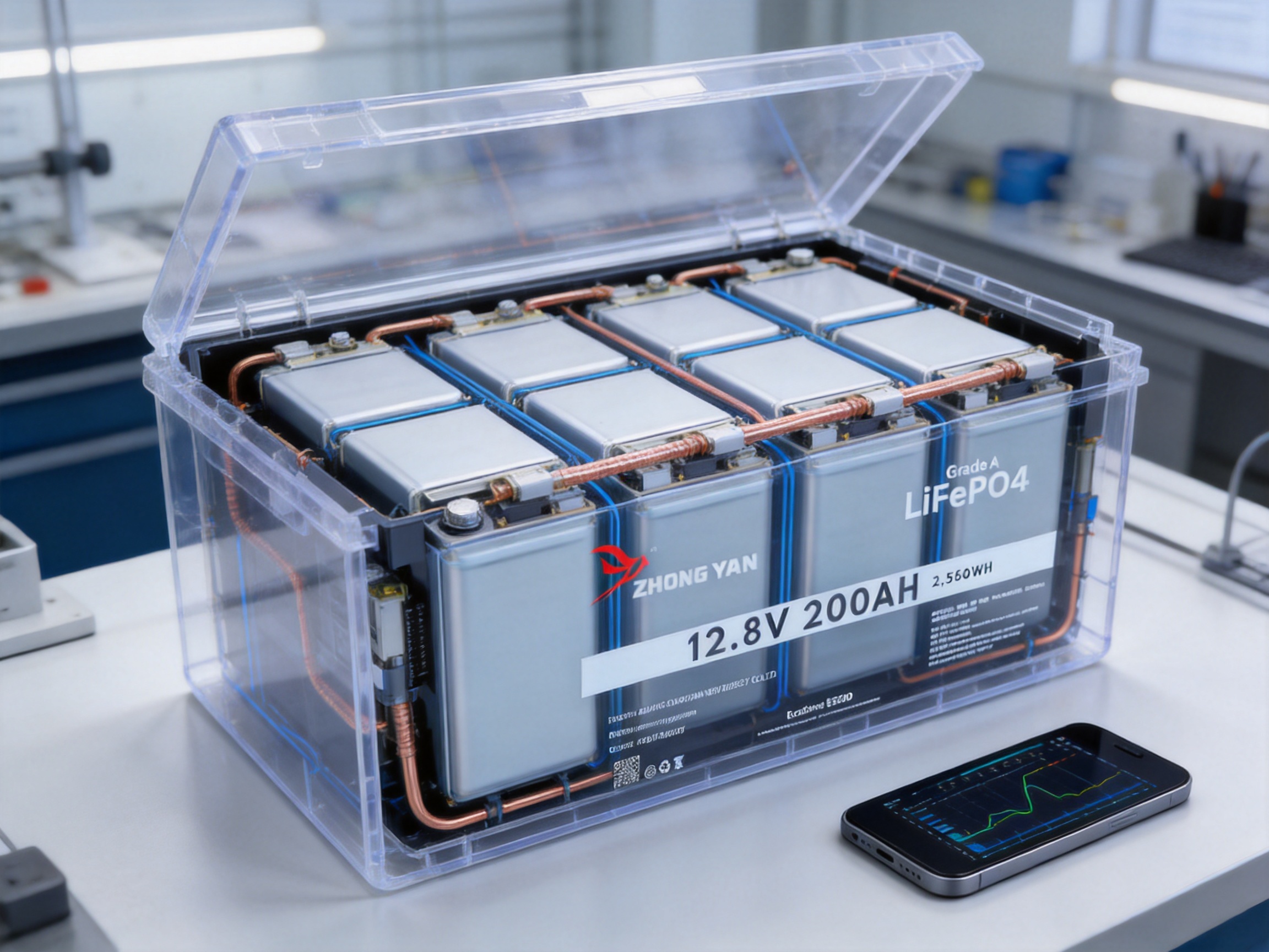
Applications for the 12.8V 200Ah Battery
Solar and Off-Grid Energy Storage
The battery can store energy generated by solar panels for use during the evening, during cloudy conditions, or when the solar source is unavailable. A 2,560Wh nominal capacity can support lighting, communication devices, refrigeration, networking equipment, small appliances, monitoring systems, and other loads depending on the operating profile.
For solar installations, the charge controller must use an appropriate LiFePO4 charging profile. The controller should be configured according to the battery manufacturer’s voltage limits and the requirements of the entire system. Solar input, inverter size, cable length, fuse ratings, and expected daily energy consumption should all be calculated before installation.
Recreational Vehicles and Mobile Power
In recreational vehicles, a lithium battery can provide a practical house-power solution for lighting, refrigeration, pumps, entertainment equipment, communications, and inverter loads. Its lower weight compared with many lead-acid banks can help preserve payload capacity.
The battery should be secured against movement and protected from extreme interior temperatures. Charging sources may include alternators, solar controllers, shore-power chargers, or DC-to-DC converters. Each charging source should be compatible with the battery’s voltage and current limits.
Marine and Coastal Equipment
The IP67 enclosure and strong current capability make this battery suitable for many marine auxiliary applications, such as navigation equipment, communications, lighting, pumps, refrigeration, and onboard electronics. Marine installations require particular attention to terminal protection, salt-air exposure, cable routing, fusing, and physical restraint.
The battery should be located in a dry, accessible, and mechanically protected compartment whenever possible. IP67 protection should be treated as an additional safeguard rather than a substitute for good marine installation practices.
Telecommunications and Backup Systems
Telecommunications equipment and remote monitoring systems often require reliable backup power with minimal maintenance. A 12.8V battery can be integrated into a DC backup architecture or combined in series and parallel to create a larger bank.
Bluetooth monitoring can help technicians check battery voltage, current, temperature, and protection status during maintenance visits. For remote or critical installations, the battery may be combined with external monitoring equipment, alarms, and automatic transfer systems.
Electric Mobility and Utility Equipment
The battery may also be considered for low-voltage utility equipment, mobile workstations, floor-cleaning equipment, access systems, and other applications that require a compact source of high-capacity DC energy. The suitability of the battery depends on the motor controller, starting current, duty cycle, vibration, environmental conditions, and required safety approvals.
System Expansion in Series and Parallel
The stated connectivity allows unlimited parallel connection and up to four batteries in series. Four batteries in series can create a nominal 51.2V battery bank, while parallel connection increases capacity and current capability.
Series connection increases voltage but does not increase amp-hour capacity. Four 12.8V, 200Ah batteries connected in series would produce approximately 51.2V and 200Ah, equivalent to 10,240Wh nominal energy. Parallel connection increases capacity at the same nominal voltage. Two identical batteries in parallel would produce approximately 12.8V and 400Ah, equivalent to 5,120Wh nominal energy.
| Configuration | Nominal voltage | Nominal capacity | Approximate nominal energy |
|---|---|---|---|
| One battery | 12.8V | 200Ah | 2,560Wh |
| Two in parallel | 12.8V | 400Ah | 5,120Wh |
| Four in series | 51.2V | 200Ah | 10,240Wh |
| Four in series and two parallel strings | 51.2V | 400Ah | 20,480Wh |
Only batteries of the same model, capacity, age, state of charge, and compatible BMS configuration should be connected together. Before connecting units in parallel or series, installers should confirm voltage matching and follow the manufacturer’s wiring and protection guidance. Each battery and each battery string may require appropriate fusing and isolation.
Charging and Installation Considerations
A LiFePO4 battery should be charged with a charger designed for lithium iron phosphate batteries. The constant-current/constant-voltage method is used: the charger supplies a controlled current until the battery reaches the target voltage, then maintains the voltage while the current gradually decreases.
The listed charging cut-off voltage is 14.8V plus or minus 0.2V. The exact charging profile should be confirmed against the BMS settings and the recommendations supplied with the specific production batch. Some systems may use a lower absorption voltage to reduce stress and improve long-term life, while others may require a particular balancing or communication strategy.
Installers should use cable cross-sections appropriate for the expected continuous and peak currents. At 200A, even a small amount of cable resistance can produce voltage drop and heat. Cable lugs should be correctly crimped, terminals should be tightened to the specified torque, and all exposed positive terminals should be protected against accidental short circuit.
External overcurrent protection remains essential. A fuse or circuit breaker should be placed as close as practical to the battery positive terminal and sized according to the cable, expected current, inverter or load requirements, and applicable electrical standards. A manual disconnect can simplify servicing and emergency isolation.
The battery should be mounted on a stable surface, protected from crushing or impact, and positioned so that inspection and disconnection are possible. It should not be installed near uncontrolled heat sources, corrosive chemicals, or locations where water can accumulate. Even with IP67 protection, the best installation is one that prevents unnecessary exposure to harsh conditions.
Safety and Protection Features
Safety is supported by the combination of stable LFP chemistry, a smart BMS, a robust ABS enclosure, internal electrical protection, and stated certifications. The listed standards include IEC62619, UL1642A, UN38.3, and RoHS. Buyers should request the relevant test reports, declarations, and shipment documentation for the exact model and configuration.
UN38.3 is especially relevant to the transportation testing of lithium batteries. IEC62619 addresses safety requirements for industrial lithium secondary cells and batteries. RoHS relates to restrictions on certain hazardous substances. Certification markings should always be verified against the product label and the documentation supplied with the shipment.
A battery must never be opened, crushed, punctured, incinerated, or exposed to unauthorized modification. If the enclosure is damaged, swollen, unusually hot, leaking, or producing an abnormal odor, it should be isolated and inspected by qualified personnel. Users should not attempt to repair internal cells or bypass the BMS.
Quality Control from Cell to Finished Pack
Reliable battery production requires control at every stage. The process begins with incoming-material verification. Cells should be checked for model, capacity, appearance, voltage, internal resistance, and traceability. Conductive parts should be inspected for dimensions, material, surface quality, and connection geometry.
During assembly, cell orientation, insulation, busbar placement, flexible-link routing, BMS wiring, temperature-sensor positioning, and fastener torque must be controlled. A single wiring error can compromise protection or cause an unsafe condition, so point-by-point inspection is essential.
Electrical testing may include insulation resistance, polarity verification, voltage measurement, capacity testing, internal resistance measurement, charge and discharge testing, BMS protection testing, Bluetooth communication checks, and simulated fault conditions. Mechanical inspection should confirm enclosure dimensions, terminal alignment, fastener security, sealing, labels, and overall appearance.
Finished-pack traceability allows a manufacturer to identify the cells, components, operators, test results, and production date associated with a battery. This is especially important for commercial, industrial, and OEM customers who need repeatability across multiple orders.
The manufacturer’s focus on precision conductive components supports this quality-control approach. Connection systems can be evaluated not only for conductivity but also for fatigue resistance, dimensional accuracy, weld consistency, and compatibility with the battery enclosure.
Why Choose This Battery for OEM and Project Applications?
Project buyers often need more than a standard retail battery. They may require customized terminals, special cable lengths, communication interfaces, enclosure modifications, mounting features, labeling, packaging, or a specific BMS configuration. A manufacturer with in-house or closely controlled capabilities in conductive components and battery assembly can respond more effectively to these requirements.
The company’s product range includes insulated flexible busbars, rigid and solid busbars, aluminum busbars, coated and painted busbars, copper braided tape, stranded copper wires, stranded copper connectors, composite laminated busbars, cell contact systems, battery storage connectors, battery terminals, and insulating covers. This broad portfolio creates opportunities for integrated sourcing.
For an OEM, the ability to obtain cells, BMS integration, copper flexible connections, busbars, terminal insulation, and battery-pack assembly from an experienced new-energy supplier can simplify engineering coordination. It can also reduce the number of interfaces between separate suppliers, provided that the supplier’s quality system, documentation, and production capacity meet the project’s needs.
Customization Possibilities
Depending on project requirements, customization may include:
• Battery capacity and cell configuration.
• Terminal position and connection method.
• Busbar or flexible-copper connection design.
• BMS current rating and protection parameters.
• Bluetooth or other communication functions.
• Enclosure dimensions and mounting points.
• Cable assemblies, connectors, fuses, and protective covers.
• Product labels, manuals, packaging, and traceability records.
• Testing procedures and acceptance criteria.
Custom engineering should be based on a documented specification. The electrical load profile, operating temperature, expected cycle count, installation environment, charging method, safety requirements, and regulatory destination should all be defined before mass production.
Total Cost of Ownership
Purchase price is only one part of battery economics. A battery that lasts longer, requires less maintenance, weighs less, and delivers more usable energy may provide a lower total cost of ownership even if its initial price is higher than that of a lead-acid alternative.
Relevant cost factors include replacement frequency, installation labor, transportation, maintenance, downtime, charging efficiency, usable energy, recycling, and system expansion. The five-year full replacement warranty listed for this battery can provide additional purchasing confidence, subject to the applicable warranty terms and operating conditions.
In daily-cycling applications, the value of long cycle life is especially significant. If a battery is used for solar energy storage every day, frequent replacement can involve not only the cost of a new battery but also labor, system shutdown, shipping, disposal, and possible damage to connected equipment. A durable LFP battery can help reduce these indirect costs.
Recommended Selection Checklist
Before ordering, buyers should confirm the exact battery configuration. The supplied materials contain an introductory reference to a 100Ah product and a detailed specification for a 200Ah product. The 200Ah version should be verified by checking the product label, data sheet, cell arrangement, and BMS rating.
Customers should also confirm:
• Whether the application requires 12.8V, 25.6V, or 51.2V system voltage.
• The continuous and peak current requirements of the load.
• The charger voltage and maximum charging current.
• The inverter’s low-voltage and high-voltage settings.
• The ambient temperature range and charging temperature conditions.
• The available mounting space and cable-routing requirements.
• Whether Bluetooth monitoring is compatible with the intended mobile device.
• The exact certification documents required in the destination market.
• The warranty conditions and exclusions.
• Requirements for parallel or series expansion.
• Delivery documentation and transportation classification.
Q&A
What is the nominal energy of the battery?
The nominal energy is approximately 2,560Wh, calculated from 12.8V multiplied by 200Ah. The actual usable energy will vary according to discharge current, temperature, inverter losses, BMS settings, and the selected depth of discharge.
What does 4S2P mean?
4S2P means four cell groups are connected in series and two identical series strings are connected in parallel. Four 3.2V cell groups create a nominal 12.8V battery, while two parallel strings provide a total capacity of 200Ah when each cell is rated at 100Ah.
Can this battery replace a 12V lead-acid battery?
It can replace many 12V-class lead-acid batteries, but the charger, inverter, alternator, wiring, mounting system, and protection devices must be compatible with LiFePO4 chemistry. The user should confirm voltage settings and current limits before making the replacement.
How many batteries can be connected together?
The supplied specification states unlimited parallel connection and up to four batteries in series. Only compatible batteries with matching voltage, capacity, condition, and BMS configuration should be connected. The complete bank must include appropriate fuses, disconnects, cables, and charging equipment.
What is the maximum continuous current?
The listed maximum continuous charging current is 200A, and the listed maximum continuous discharge current is also 200A. The practical current may need to be lower depending on cable size, terminal temperature, ambient temperature, inverter requirements, and the desired service life.
What is the purpose of the smart BMS?
The smart BMS monitors cell-group voltage, battery current, and temperature while providing protection against overcharge, over-discharge, over-current, over-temperature, and short circuit conditions. It also supports Bluetooth monitoring through a compatible application.
Can the battery be charged in cold weather?
The listed charging range is -10°C to 65°C. However, charging at very low temperatures should be carefully controlled, and the battery should not be charged outside the approved operating range. A temperature-controlled installation is preferred in cold climates.
Is the battery waterproof?
The enclosure is specified as IP67, meaning it is designed for dust protection and temporary immersion under defined test conditions. Correct installation is still required. Cable connections, terminals, mounting points, and surrounding equipment must also be protected from water and corrosion.
What types of applications are suitable?
Suitable applications may include solar storage, off-grid power, recreational vehicles, marine auxiliary systems, telecommunications backup, emergency power, mobile workstations, and industrial equipment. The exact suitability depends on the load profile, current demand, environmental conditions, and required certifications.
Why are internal copper connections important?
Internal connections carry high current and must withstand electrical, thermal, and mechanical stress. Low-resistance copper connections can reduce voltage drop and heat generation. Flexible connections can also accommodate vibration and expansion, helping protect cell terminals and improve pack durability.
What should buyers verify because of the capacity information?
The provided materials include both a 100Ah reference and a detailed 200Ah specification. Buyers should verify the exact model name, cell configuration, rated capacity, BMS rating, product label, and test documentation before purchase. The detailed specifications identify the product as a 200Ah, 4S2P battery.
What warranty is listed?
The supplied specification lists a five-year full replacement warranty. Buyers should review the complete warranty document for coverage, installation requirements, operating limits, transportation conditions, and exclusions.
Conclusion
The 12.8V 200Ah LiFePO4 battery is designed for users who need substantially more usable energy, longer service life, lower maintenance, and stronger current performance than conventional lead-acid technology can typically provide. Its 2,560Wh nominal energy, 4S2P Grade A prismatic-cell architecture, 200A smart BMS, Bluetooth monitoring, IP67 ABS enclosure, and broad temperature specifications make it suitable for a wide range of mobile, marine, backup, renewable-energy, and industrial applications.
Its competitive value also comes from the manufacturing capabilities behind the pack. Experience in copper busbars, flexible battery connections, precision conductive parts, polymer diffusion welding, laser processing, testing, and new-energy component engineering supports the development of low-resistance and mechanically reliable current paths. These capabilities are particularly important for OEM customers and project buyers requiring customized battery assemblies or integrated conductive systems.
For the best results, the battery should be selected, installed, charged, and expanded according to a complete system design. Buyers should verify the exact 200Ah configuration, confirm the applicable documentation, use compatible charging equipment, provide proper overcurrent protection, and follow the specified temperature and current limits. When correctly integrated, this battery can serve as a durable and scalable foundation for modern low-voltage energy storage.
References
1. International Electrotechnical Commission, IEC 62619, Safety Requirements for Secondary Lithium Cells and Batteries for Use in Industrial Applications.
2. United Nations, Manual of Tests and Criteria, Part III, Subsection 38.3, Lithium Battery Transportation Testing.
3. Underwriters Laboratories, UL 1642, Standard for Lithium Batteries.
4. Restriction of Hazardous Substances Directive, RoHS Compliance Principles and Material Restrictions.
5. Battery manufacturer’s supplied technical specifications for the 12.8V 200Ah LiFePO4 battery.
6. Battery management system operating principles for lithium iron phosphate energy-storage applications.
7. General engineering practices for lithium battery installation, overcurrent protection, cable sizing, and series-parallel battery-bank design.
Product: EleStore 200Ah 12.8V LiFePO4 Battery -(EVE Cells) & (Bluetooth BMS -JBD)

Driven by the development of new energy and aiming for "zero carbon".
Copyright © Zhejiang Zhongyan New Energy Co., Ltd. All Rights Reserved.
