 English
 Español

< h1>PBCR Series Soft Braided Tape for Flexible High-Current Busbar Connections
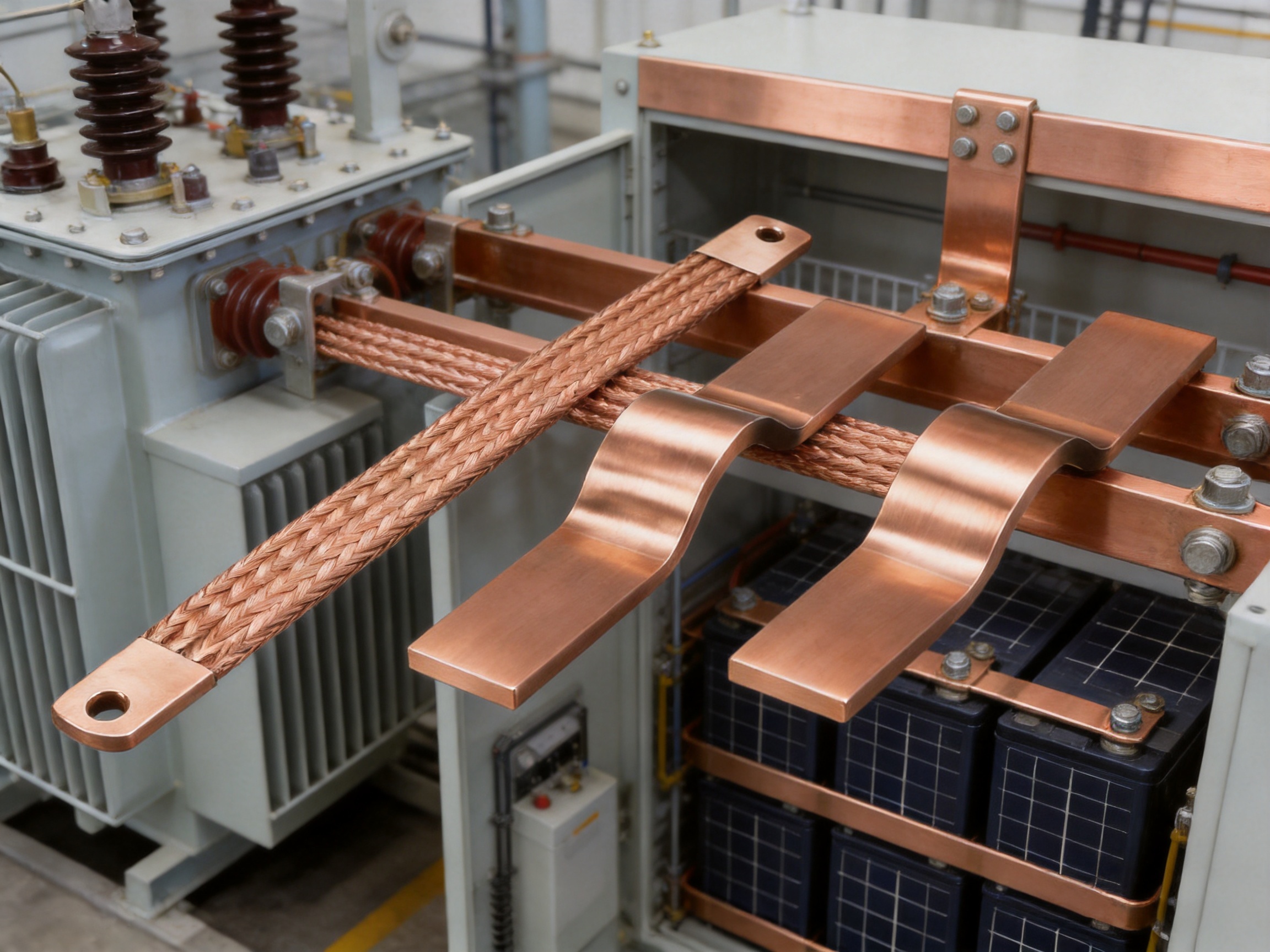
Modern electrical systems require connections that combine high current capacity, mechanical flexibility, vibration resistance, dimensional accuracy, and long-term reliability. Conventional rigid conductors can provide excellent conductivity, but they may transfer vibration, thermal expansion, and installation stress directly to connected equipment. In applications such as transformers, switchgear, power distribution assemblies, battery systems, welding equipment, and industrial machinery, this mechanical stress can shorten service life and complicate installation.
The PBCR Series Soft Braided Tape is designed to address these challenges through a flexible electrolytic copper construction, integrated connectors, and ready-to-use mounting holes. It functions as a high-current flexible connector between busbars, transformer terminals, equipment terminals, grounding points, and other conductive assemblies. By combining the braided conductor and terminal connection into one finished component, the product reduces the need for separate tinning, pressing, or field assembly operations.
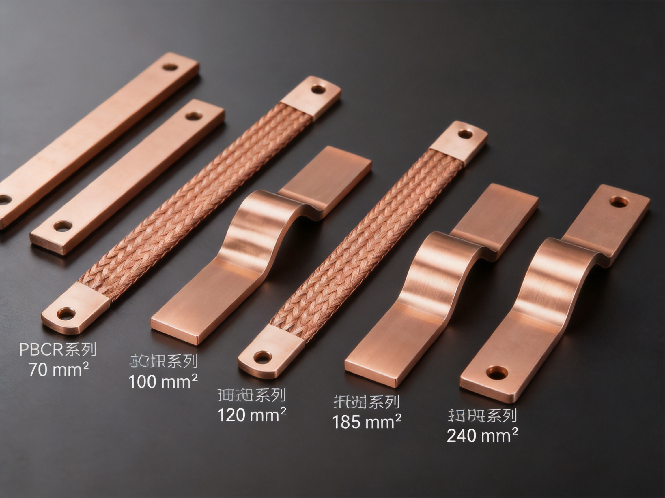
Available in cross-sectional areas from 70 mm² to 240 mm², the PBCR Series supports a broad range of current transmission requirements. The product family includes multiple lengths and terminal-hole configurations, allowing engineers to select a suitable connection according to current, installation space, bolt size, vibration level, and required movement allowance.
Manufactured by Zhejiang Zhongyan New Energy Co., Ltd., the product reflects the company’s specialization in precision conductive components, soft electrical connections, battery interconnections, and new-energy electrical systems. The company combines experienced engineering teams, specialized production equipment, modern quality management, and process development capabilities to provide stable and customized flexible connection solutions.
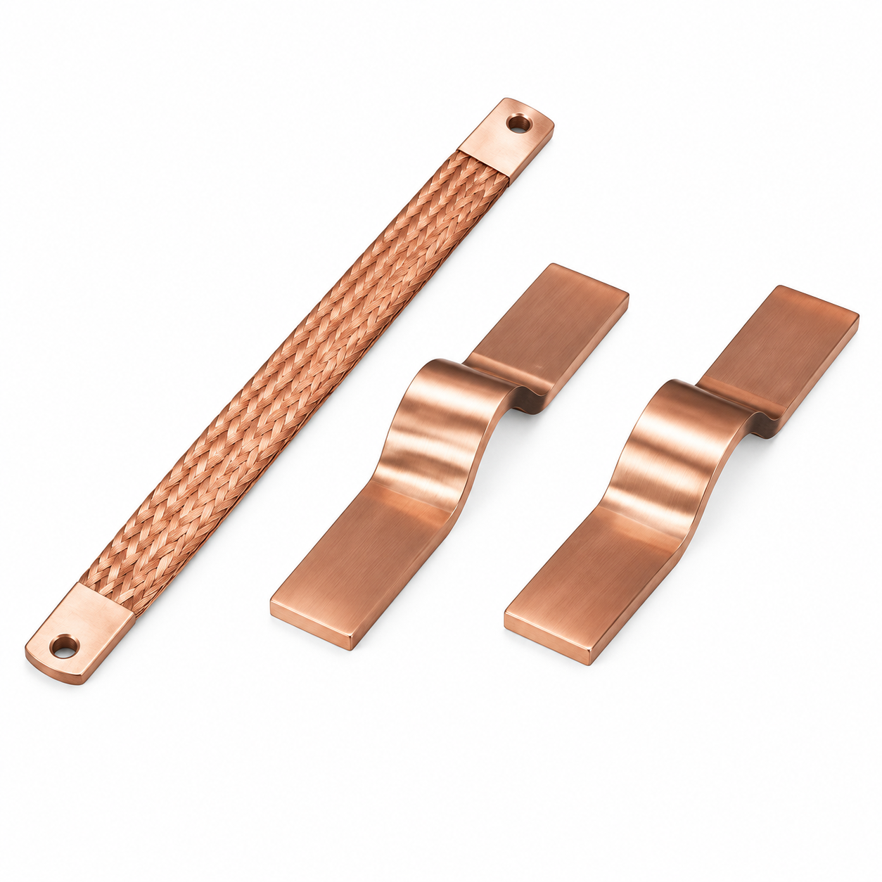
PBCR Series Soft Braided Tape
< h2>1. What Is a Soft Braided Tape Connection?A soft braided tape connection is a flexible electrical conductor made by weaving or braiding many fine copper wires into a flat, highly compliant structure. Unlike a solid copper bar, the braided conductor can bend, twist slightly, and absorb movement without placing excessive force on the connected terminals. The large number of individual wires also creates a broad conductive path with excellent flexibility.
The PBCR Series uses electrolytic copper wire with an individual wire diameter of approximately 0.15 mm. Fine wires provide a greater number of bending points throughout the conductor. Instead of forcing one solid piece of metal to flex at a single location, the braided assembly distributes movement across many small copper strands.
The result is a conductor that can accommodate equipment vibration, thermal expansion, minor alignment differences, and repeated mechanical movement. This makes the product particularly valuable where rigid busbars are unsuitable or where an expansion joint would otherwise need to be designed and installed separately.
The PBCR Series also includes integrated connector ends with mounting holes. This construction is ready for installation and eliminates several processing steps that may be necessary with loose braided tape. The finished component can be positioned between two conductive terminals and secured with the appropriate hardware, subject to the equipment manufacturer’s installation requirements.
2. Product Structure and Operating Principle
The electrical performance of the PBCR Series is based on the combined effect of its copper cross-sectional area, conductive material, braided geometry, and finished terminal configuration. The copper wires form parallel conductive paths. As the number and total cross-sectional area of wires increase, the assembly can carry greater current under the specified temperature-rise conditions.
The braided geometry gives the conductor its soft and flexible characteristics. It permits movement in multiple directions and helps reduce the transmission of vibration between connected components. In transformer applications, for example, the connection can accommodate movement caused by electromagnetic forces, operating vibration, and changes in temperature.
The terminal sections provide a practical interface with busbars, equipment terminals, grounding points, and other conductive parts. The mounting holes are integrated into the finished connector rather than being created during field installation. This improves installation consistency and supports repeatable positioning in production assemblies.
Depending on the selected model, the terminal-hole dimensions include configurations based on approximately 8.5 mm, 10.5 mm, and 12.5 mm hole sizes. The product range also includes different terminal widths and spacing dimensions. These choices help engineers match the flexible connection to the bolt diameter, terminal geometry, and available installation space.
3. Main Product Advantages
3.1 High Electrical Conductivity
Electrolytic copper is used because it combines high electrical conductivity with good ductility and reliable manufacturability. The copper braid creates a conductive connection with low electrical resistance when correctly installed on clean, properly prepared terminal surfaces.
High conductivity helps reduce voltage drop and heat generation at the connection. In high-current equipment, even a small increase in resistance can produce significant power loss and localized heating. A properly selected PBCR model can support efficient current transmission while maintaining the flexibility required by the installation.
3.2 High Flexibility
The most important difference between a braided flexible connector and a rigid busbar is mechanical compliance. The PBCR Series can flex in response to movement without requiring the entire electrical assembly to move with it. This helps protect terminal interfaces, insulators, bolts, and surrounding components from unnecessary mechanical stress.
Flexibility is especially useful where terminals are not perfectly aligned, where equipment must be removed for maintenance, or where two parts experience different levels of vibration. It also makes routing easier in compact equipment because the connector can follow a controlled bend rather than requiring a rigid, precisely formed bar.
3.3 Vibration Reduction
Electrical equipment may experience vibration from transformers, motors, generators, fans, switching operations, transport, or electromagnetic forces. A rigid conductor can transmit this vibration directly to connection points. Over time, such stress may contribute to loosening, fatigue, cracking, or damage to adjacent insulation.
The braided structure of the PBCR Series helps isolate and absorb part of this movement. The connector does not eliminate all mechanical forces, and it must still be installed with suitable support and fastening, but its flexible construction reduces the mechanical coupling between connected components.
3.4 Integrated Connector Design
The PBCR Series combines the soft braided conductor with integrated terminals and mounting holes. This ready-to-use design provides an advantage over loose braid that must be cut, formed, tinned, pressed, and fitted with separate terminals.
Reducing the number of assembly steps can shorten production time and improve consistency. It also helps reduce dependence on field workmanship. When the terminal geometry, conductor length, and hole position are supplied as a finished part, assembly personnel can focus on correct alignment, fastening torque, and electrical contact preparation.
3.5 Reduced Weight Compared with Rigid Assemblies
A flexible copper braid can reduce the weight and installation burden of a connection compared with a large solid copper bar or a multi-part rigid joint. Weight reduction can be useful in mobile equipment, compact switchgear, battery enclosures, renewable-energy systems, and assemblies where supporting structures must be minimized.
The exact weight depends on cross-sectional area and length. For example, the listed PBCR products range from approximately 0.17 kg to 1.07 kg per unit. Engineers can therefore select a model that provides the required electrical capacity without adding unnecessary material.
3.6 Suitability for Expansion and Movement
Temperature changes cause copper conductors, busbars, terminals, and equipment housings to expand and contract. If a rigid connection is installed between components with different thermal behavior, the resulting movement may place stress on bolts and terminal surfaces.
A flexible braided connector provides a compliant section that can absorb a portion of this dimensional change. This is one reason flexible connections are widely used in transformer busbar slots, switchgear, power distribution assemblies, and other equipment exposed to repeated thermal cycles.
3.7 Simplified Installation
The preconfigured length and integrated holes make the PBCR Series suitable for repeatable installation. The installer does not need to create a custom connection from separate copper braid and terminal pieces for every assembly. This may improve production efficiency, reduce material waste, and support more consistent electrical performance.
4. Comparison with Conventional Connection Methods
Rigid copper bars provide excellent structural support and can be a good choice where the connected components are fixed, aligned, and protected from vibration. However, a rigid bar may require precise bending, machining, drilling, deburring, plating, and insulation clearance. It can also transfer mechanical stress directly into the equipment.
Loose copper braid offers flexibility, but it may require additional terminals, pressing, tinning, or other end treatments before it can be installed. The quality of the final connection then depends on the field or assembly process. Inconsistent pressing pressure, incorrect terminal alignment, or inadequate surface preparation can increase resistance and reduce reliability.
Flexible cables are also widely used, but they may require crimped lugs, larger bending radii, insulation stripping, and additional routing space. A flat braided connector can be more suitable where a low-profile, high-current connection is needed and where the distance between terminals is relatively short.
The PBCR Series combines the principal benefits of these approaches: the conductivity of copper, the movement tolerance of a flexible conductor, and the installation convenience of a finished connector. It is not intended to replace every rigid busbar or cable application. Instead, it serves as a specialized connection solution for locations where flexibility, vibration resistance, and high current are priorities.
5. Available PBCR Series Specifications
The following table summarizes the primary models provided for the PBCR Series. Current ratings are shown for temperature-rise conditions of 30 K and 50 K. Actual allowable current depends on installation orientation, ambient temperature, contact resistance, ventilation, duty cycle, enclosure design, and applicable engineering standards.
| Part Number | Description | Cross Section (mm²) | Current at Δ30 K (A) | Current at Δ50 K (A) | Length L (mm) | Hole Diameter 1 (mm) | Hole Diameter 2 (mm) | Packaging | Weight (kg) |
|---|---|---|---|---|---|---|---|---|---|
| 23000402 | PBCR 70-230-8-10 | 70 | 226 | 362 | 291 | 8.5 | 10.5 | 2 | 0.17 |
| 23000403 | PBCR 70-330-8-10 | 70 | 226 | 362 | 291 | 8.5 | 10.5 | 2 | 0.24 |
| 23000404 | PBCR 70-430-8-10 | 70 | 226 | 362 | 291 | 8.5 | 10.5 | 2 | 0.30 |
| 23000405 | PBCR 100-230-8-10 | 100 | 298 | 477 | 385 | 8.5 | 10.5 | 2 | 0.24 |
| 23000406 | PBCR 100-330-8-10 | 100 | 298 | 477 | 385 | 8.5 | 10.5 | 2 | 0.34 |
| 23000407 | PBCR 100-430-8-10 | 100 | 298 | 477 | 385 | 8.5 | 10.5 | 2 | 0.44 |
| 23000408 | PBCR 120-230-10 | 120 | 363 | 581 | 468 | 10.5 | 10.5 | 2 | 0.29 |
| 23000409 | PBCR 120-330-10 | 120 | 363 | 581 | 468 | 10.5 | 10.5 | 2 | 0.41 |
| 23000410 | PBCR 120-430-10 | 120 | 363 | 581 | 468 | 10.5 | 10.5 | 2 | 0.53 |
| 23000411 | PBCR 185-330-10-12 | 185 | 416 | 666 | 537 | 10.5 / 12.5 | 12.5 | 2 | 0.64 |
| 23000412 | PBCR 185-430-10-12 | 185 | 416 | 666 | 537 | 10.5 / 12.5 | 12.5 | 2 | 0.82 |
| 23000413 | PBCR 240-330-10-12 | 240 | 556 | 890 | 718 | 10.5 / 12.5 | 12.5 | 2 | 0.83 |
| 23000414 | PBCR 240-430-10-12 | 240 | 556 | 890 | 718 | 10.5 / 12.5 | 12.5 | 2 | 1.07 |
The product naming convention generally identifies the cross-sectional area, connection length, and terminal-hole configuration. Engineers should confirm the complete dimensional drawing before placing an order because the description may use compact notation and some applications require additional dimensions such as terminal width, center spacing, bolt clearance, or bend allowance.
6. Understanding the Current Ratings
The table provides current-carrying values at two temperature-rise conditions. A 30 K temperature rise represents a more conservative operating condition than a 50 K temperature rise, assuming the same test or calculation method. The higher current value does not mean that every installation should operate continuously at that level. The allowable operating current must be evaluated within the complete electrical and thermal system.
Current capacity can be affected by natural convection, forced cooling, enclosure ventilation, proximity to other conductors, surface contact, installation direction, ambient temperature, and duration of operation. Parallel flexible connectors may also change the heat distribution and magnetic environment.
For this reason, the PBCR rating should be treated as a design reference rather than a substitute for system-level verification. High-current applications should be checked through temperature-rise testing, thermal calculation, or both. Contact surfaces must be clean and flat, and fastening hardware must be selected and tightened according to the equipment design.
The PBCR family includes current capacities from 226 A to 556 A at the listed 30 K condition and from 362 A to 890 A at the listed 50 K condition. These values cover many industrial and power-distribution applications. The broader product description also identifies the product family as suitable for high-current connections, with application strength stated up to 4,600 A when appropriate configurations or assemblies are used.
7. Manufacturing Process and Engineering Strengths
7.1 Material Selection
Manufacturing begins with the selection of suitable electrolytic copper wire. The approximately 0.15 mm wire diameter provides a balance between conductivity, flexibility, braid stability, and production performance. Material consistency is important because variations in wire diameter, copper purity, surface condition, or mechanical properties can affect resistance and flexibility.
Material controls should include incoming inspection, dimensional verification, surface evaluation, and traceability where required by the customer. Consistent raw material supports stable braiding and helps maintain repeatable electrical and mechanical properties across production batches.
7.2 Precision Braiding
The copper wires are formed into a braided tape using specialized equipment. Braiding tension, wire guidance, braid density, width, thickness, and edge condition all influence the final product. Excessive tension can reduce flexibility, while insufficient control may create uneven geometry or inconsistent cross-sectional area.
Advanced process control allows the manufacturer to produce a stable flat braid while preserving the soft structure required for vibration absorption. The production team can adjust the braid construction according to the required cross section and connection design.
7.3 Terminal Formation
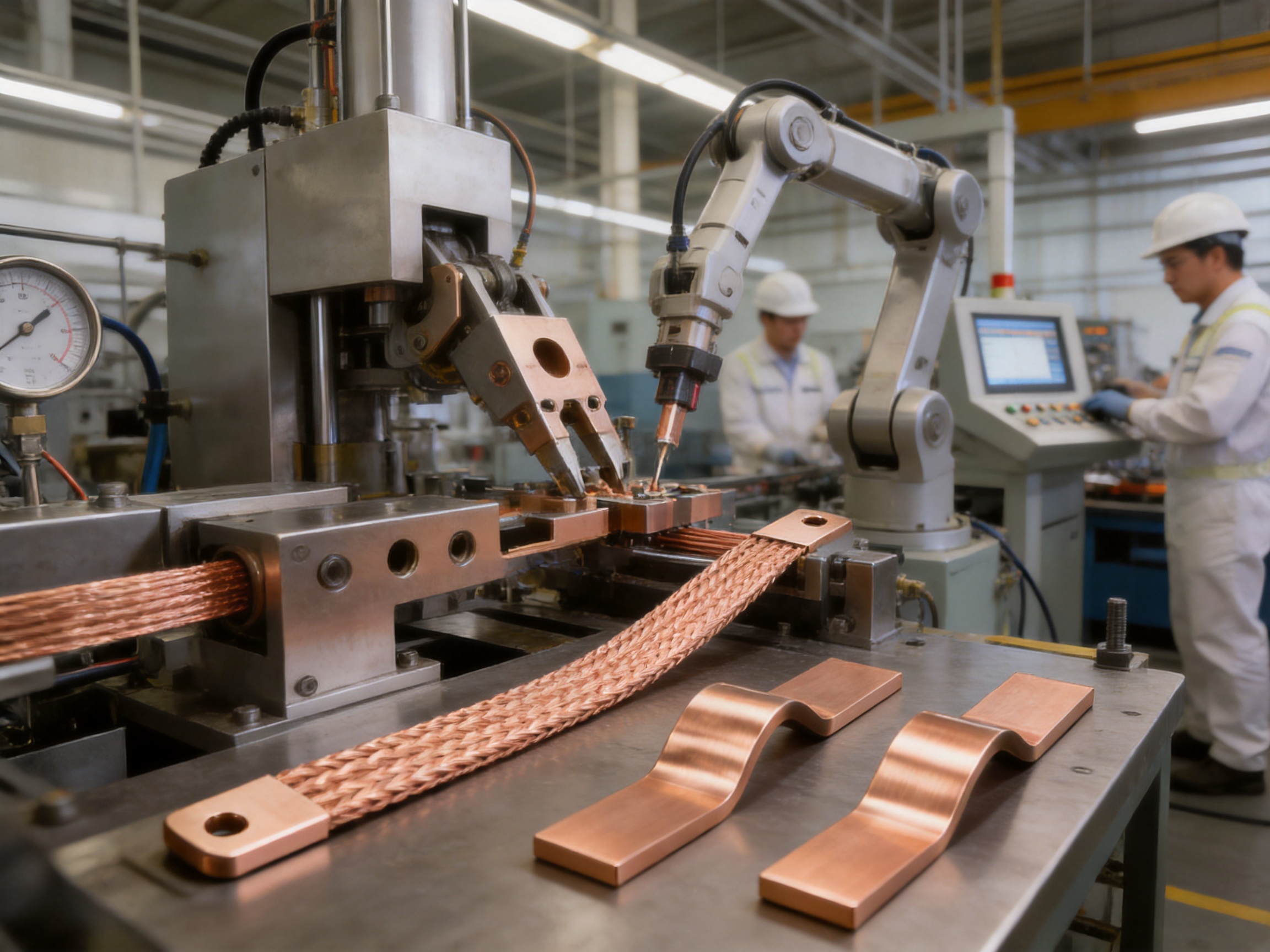
The braided conductor must be connected to robust terminal sections capable of transferring high current without creating excessive resistance. Terminal formation may involve controlled pressing, shaping, joining, and hole processing. The objective is to create a stable transition between the flexible braid and the rigid mounting area.
This transition zone is especially important because it experiences both electrical current and mechanical movement. If the transition is too rigid, stress can concentrate at the braid edge. If it is insufficiently formed, the connection may experience increased resistance or mechanical instability. Controlled production equipment and repeatable tooling help maintain a consistent terminal geometry.
7.4 Hole Processing and Dimensional Control
Integrated mounting holes must be positioned accurately to ensure correct installation and full contact with the mating terminal. Hole diameter, center distance, terminal width, edge clearance, and flatness should be controlled during production.
Accurate hole processing reduces installation difficulty and prevents forced alignment. A connector that fits naturally can be tightened evenly, while a connector that must be twisted or pulled into position may introduce unwanted mechanical stress.
7.5 Joining Technologies
The company has developed capabilities in specialized joining technologies, including polymer diffusion welding and laser technology for new-energy precision components. These technical capabilities support the broader manufacturing system and demonstrate experience with low-resistance, high-reliability conductive joints.
Different PBCR configurations may require different joining or forming methods according to material thickness, terminal structure, current requirement, and customer specification. Process selection should be based on electrical resistance, mechanical strength, heat-affected area, production repeatability, and compatibility with the final assembly.
7.6 Inspection and Verification
Quality control for flexible copper connections should cover both electrical and mechanical characteristics. Typical inspection categories include dimensional verification, visual inspection, terminal-hole accuracy, braid consistency, joint integrity, contact resistance, tensile performance, and flexibility.
Production quality systems also help identify process variation before it affects large quantities. Sampling plans, equipment maintenance, process records, and traceability support stable manufacturing and provide useful information for continuous improvement.
8. Why Integrated Production Matters
A flexible connector is not simply a length of copper braid. Its performance depends on the relationship between material, braid construction, terminal design, joining process, dimensional accuracy, and final inspection. A manufacturer with integrated engineering and production capabilities can optimize these factors together rather than treating each operation as an isolated purchase.
Integrated production allows the design team to modify the conductor cross section, terminal shape, mounting hole, length, and joining method as one system. This is particularly valuable for original equipment manufacturers that require a component to fit a specific busbar arrangement or battery assembly.
It also supports faster technical communication. Customers can provide drawings, current requirements, installation constraints, or samples, and the manufacturer can evaluate the complete connection rather than offering only a generic braid. This approach is useful for new product development, platform standardization, and replacement of oversized rigid connections.
9. Application in Transformer Busbar Connections
Transformers commonly experience vibration and temperature variation during operation. The magnetic forces generated within the transformer, together with thermal cycling and structural movement, can place stress on busbar connections. A flexible braided connector can provide a compliant transition between the transformer terminal and an external busbar or switchgear connection.
The PBCR Series is identified as a preferred product for transformer busbar slot connections. Its flexible body can help accommodate movement while maintaining a high-conductivity path. Its integrated holes also simplify connection to prepared transformer terminals and busbar interfaces.
When applied in a transformer, engineers should evaluate creepage and clearance, insulation coordination, short-circuit forces, thermal performance, support arrangement, and access for maintenance. The flexible connector should not be allowed to carry unsupported mechanical loads from adjacent busbars. Proper routing and support are essential.
10. Application in Switchgear and Power Distribution
Switchgear assemblies often contain compact conductors, movable components, circuit breakers, disconnectors, and busbar compartments. A flexible connector can be used where a rigid bar would interfere with movement or where vibration isolation is needed between sections.
The PBCR Series may also be considered for links between busbars and equipment terminals, grounding connections, transformer sections, and high-current internal distribution points. The flat profile can help maintain a compact layout, while the available lengths provide flexibility when the terminal distance differs between equipment models.
Switchgear designers must ensure that the connector does not reduce required insulation distances or interfere with moving mechanisms. Short-circuit withstand requirements should be considered separately from continuous current capacity because fault forces can be much greater than normal operating forces.
11. Application in Grounding and Welding Systems
The product information identifies a 100 mm² application for grounding and welding. These systems often require high current, mechanical flexibility, and resistance to movement. Welding equipment may involve repeated repositioning, vibration, and short-duration high-current operation.
For grounding applications, the connection must provide a reliable low-impedance path under normal and fault conditions. The mounting interface should be protected against loosening, corrosion, contamination, and accidental mechanical damage. The connector should be routed to avoid sharp bends that could concentrate stress at the terminal transition.
For welding applications, the duty cycle and current waveform should be considered. Actual performance depends on the welding process, operating duration, ambient conditions, and cooling. The product should be selected and validated according to the equipment manufacturer’s electrical and thermal requirements.
12. Application in Batteries and Energy Storage
Energy-storage systems require compact, low-resistance connections that can tolerate thermal cycling and equipment vibration. Battery modules may expand slightly during operation, while enclosures and busbar supports can experience movement during transportation and service. Flexible copper connections can reduce stress between cells, modules, busbars, and power terminals.
The PBCR Series belongs to a broader product portfolio that includes battery soft connections, battery storage connectors, cell contact systems, and other conductive components. This experience enables the manufacturer to understand the importance of low internal resistance, compact geometry, precise hole positioning, and repeatable production in energy-storage applications.
The PBCR Series may be suitable for larger-current links within energy-storage equipment where a braided tape connection is preferred. However, battery applications require additional evaluation of insulation, creepage, short-circuit protection, enclosure safety, cell chemistry, thermal propagation, and service procedures.
The manufacturer is also expanding its capabilities in lithium battery manufacturing and integrated cell and connection-system design. This direction supports a more complete understanding of the relationship between battery cells, current collectors, busbars, soft connections, and system-level safety.
13. Application in Renewable-Energy Equipment
Solar inverters, energy-storage converters, wind-power equipment, and other renewable-energy systems can contain high-current DC and AC connections. These systems may be installed in environments with temperature fluctuation, vibration, limited space, or frequent power cycling.
A flexible braided connection can provide a practical link between power electronics and busbar assemblies. It can help compensate for installation tolerances and reduce mechanical loading on semiconductor modules, capacitors, terminals, and enclosure-mounted conductors.
In renewable-energy equipment, the connector should be evaluated for continuous current, peak current, switching frequency, electromagnetic forces, heat dissipation, and service accessibility. A model with the correct cross-sectional area may still require additional thermal management if it is installed in a confined enclosure.
14. Customization Capabilities
Standard PBCR models simplify selection and shorten procurement time, but many equipment designs require customized dimensions. The manufacturer can support customized solutions based on current, length, terminal-hole size, terminal width, installation direction, and available space.
Customization may involve a different cross-sectional area, a non-standard length, alternative hole spacing, special terminal geometry, or a modified joining structure. Customers can provide two-dimensional drawings, three-dimensional models, samples, or application specifications for technical review.
A successful custom design should begin with the complete application rather than only the nominal current. Relevant information includes continuous and peak current, acceptable temperature rise, ambient temperature, installation enclosure, movement range, vibration, terminal material, fastening method, insulation requirements, and expected service life.
Customized development can also help replace multiple components with one integrated connection. For example, a customer may be able to eliminate a rigid busbar extension, separate expansion joint, and additional connector hardware by using a purpose-designed flexible copper assembly.
15. Installation Guidelines
15.1 Confirm the Model
Before installation, verify the part number, cross-sectional area, length, terminal-hole size, and mounting orientation. The selected connector must match the mating terminals and the required current conditions.
15.2 Inspect Contact Surfaces
Contact surfaces should be clean, flat, and free from dirt, oxide buildup, burrs, paint, or other contamination that could increase contact resistance. Surface treatment should follow the equipment design and applicable electrical practice.
15.3 Avoid Forced Alignment
The connector should be installed without excessive pulling, twisting, or lateral force. If the holes do not align naturally, the cause should be corrected rather than using bolts to force the connector into position. Forced alignment may create continuous stress at the terminal transition.
15.4 Use Suitable Fasteners
Fasteners, washers, nuts, and torque values should be selected according to the mating terminal and equipment design. The mounting hardware must provide a stable contact pressure throughout the operating temperature range and vibration environment.
15.5 Provide Mechanical Support
A flexible connector should not be used as a substitute for structural support. Adjacent rigid busbars and equipment should be supported independently so that the braid carries electrical current and controlled movement rather than the weight of the assembly.
15.6 Check Thermal Performance
After installation, the connection should be evaluated under representative load conditions. Temperature measurement can identify inadequate contact, excessive current concentration, poor ventilation, or unexpected heat transfer from nearby components.
16. Design Considerations for Engineers
Engineers should define the operating current based on real duty conditions rather than relying only on nominal equipment ratings. Continuous current, overload duration, fault current, pulse current, and duty cycle can all influence conductor selection.
Mechanical movement should also be quantified. The design should identify the expected direction and amplitude of vibration, thermal expansion, installation tolerance, and maintenance movement. The connector length should provide sufficient flexibility without creating an uncontrolled loop or interfering with nearby components.
Electrical clearances must be checked after the connector is bent into its final position. A flexible component may move during installation or service, so the design should include appropriate restraint and clearance from grounded surfaces, sharp edges, insulation, and moving equipment.
Where multiple flexible connectors are installed in parallel, the current-sharing arrangement should be reviewed. Differences in length, contact resistance, routing, and cooling may cause uneven current distribution. Parallel connections should be mechanically and electrically symmetrical where possible.
17. Reliability Benefits Compared with Less Integrated Alternatives
The PBCR Series can improve connection reliability by reducing the number of separate parts and field operations. Every additional joint, pressed terminal, or manually prepared interface creates another potential source of variation. An integrated connector does not eliminate the need for careful installation, but it provides a more controlled starting point.
Repeatable dimensions also support consistent assembly across production batches. When a manufacturer produces the braid, terminal, and holes under controlled processes, the customer can standardize work instructions and reduce adjustment time on the assembly line.
The flexible structure contributes to reliability by reducing the transfer of vibration and thermal movement. This benefit is particularly important for equipment that operates continuously, cycles frequently, or contains sensitive terminals and electronic components.
18. Company Manufacturing and Technical Capability
Zhejiang Zhongyan New Energy Co., Ltd. is a high-tech enterprise specializing in new-energy conductive components and precision electrical connection products. Its product focus includes high-voltage copper-foil soft connections, special-shaped flexible connections, battery soft connections, and other customized conductive components.
The company has experienced engineers and technical teams supported by specialized production equipment. Its capabilities cover product design, research and development, manufacturing, testing, verification, and solution development. This combination is important for flexible connectors because the final product must satisfy electrical, mechanical, dimensional, and application-specific requirements at the same time.
Established in 2022, the company has focused on precision components for batteries and new-energy systems while continuing to expand into lithium battery manufacturing and integrated battery connection systems. Its development work includes polymer diffusion welding and laser technology intended to support low internal resistance and high-reliability conductive joints.
The company reports supplying leading enterprises in the automotive and battery sectors. Such applications generally require stable dimensions, low resistance, process repeatability, and strong quality management. Experience in these demanding industries supports the development of flexible busbar and braided connection products for industrial customers.
19. Quality Management Approach
Quality in a flexible copper connector must be built into each stage of production. Incoming material controls help ensure that the copper wire meets the required dimensions and surface condition. Braiding controls maintain a stable cross section and flexible structure. Terminal forming and joining controls support mechanical strength and low resistance.
Final inspection should verify the features that directly affect installation and performance. These may include part length, hole diameter, hole position, terminal width, braid appearance, joint condition, and weight. Electrical resistance and mechanical tests can be used according to the customer’s specification and application risk.
Modern quality management also requires documented process parameters, equipment maintenance, operator training, nonconformance control, and corrective action. These measures help transform individual production experience into a repeatable manufacturing system.
20. Environmental and Lifecycle Considerations
Copper is a durable and recyclable conductive material. A long-life flexible connection can help reduce maintenance frequency and replacement material over the service life of electrical equipment. The product’s reduced weight compared with some rigid assemblies may also lower material usage and simplify transportation.
Lifecycle performance depends on correct selection and installation. Exposure to moisture, corrosive chemicals, excessive heat, repeated overcurrent, or mechanical abrasion can affect copper connections. Equipment designers should specify suitable protection and inspection practices for the operating environment.
In renewable-energy and energy-storage equipment, reliable conductive components contribute to efficient power conversion and stable operation. By supporting new-energy electrical systems, flexible copper connections can form part of broader efforts to improve power efficiency, equipment durability, and system integration.
21. How to Select the Correct PBCR Model
Start by identifying the continuous current and the acceptable temperature rise. Select a cross-sectional area that provides sufficient capacity under the actual installation conditions rather than choosing only by nominal equipment current.
Next, confirm the required connection length. The length should permit natural installation and movement without excessive slack. A connector that is too short may be overstressed, while one that is too long may contact nearby components or create unnecessary electromagnetic and mechanical movement.
Then verify the terminal-hole configuration. The hole diameter must match the fastener and mating terminal, and the terminal width must provide adequate contact area. For larger connections, confirm the 10.5 mm and 12.5 mm configurations carefully against the equipment drawing.
Finally, evaluate the environment. Consider vibration, temperature, humidity, enclosure space, maintenance access, short-circuit forces, insulation requirements, and expected operating life. For specialized equipment, provide these details to the manufacturer for technical confirmation and possible customization.
22. Frequently Asked Questions
What is the PBCR Series Soft Braided Tape used for?
It is used as a flexible, high-current copper connection between busbars, transformer terminals, switchgear, grounding points, welding equipment, battery assemblies, and other electrical components that require vibration absorption or thermal movement compensation.
What material is used in the braided conductor?
The product uses electrolytic copper wire with an individual wire diameter of approximately 0.15 mm. The fine-wire construction provides conductivity, flexibility, and resistance to repeated movement.
Does the product require tinning or pressing during installation?
The PBCR Series is supplied as an integrated connector with finished mounting holes. It is designed to reduce the need for separate tinning, pressing, or field fabrication. Installation still requires correct alignment, suitable fasteners, proper contact preparation, and the required tightening procedure.
What cross-sectional areas are available?
The listed standard models include 70 mm², 100 mm², 120 mm², 185 mm², and 240 mm² versions. Other sizes may be evaluated for customized applications.
What current can the PBCR Series carry?
Listed current values range from 226 A to 556 A at a 30 K temperature rise and from 362 A to 890 A at a 50 K temperature rise, depending on the model. The broader product family is also described for high-current applications up to 4,600 A when suitable configurations or assemblies are used. Final selection must consider the complete thermal and electrical installation.
Can the product be used in transformer connections?
Yes. The product is identified as suitable for transformer busbar slot connections. Its flexible structure helps accommodate vibration and thermal movement between transformer terminals and busbar systems.
Can PBCR connectors be customized?
Customization can be considered for length, cross-sectional area, hole size, terminal geometry, spacing, and other dimensional requirements. Customers should provide application data or drawings for engineering review.
Is the PBCR Series suitable for battery systems?
It can be considered for high-current links in battery and energy-storage equipment when its dimensions, insulation arrangement, current rating, and thermal behavior meet the system requirements. Battery applications require additional validation for short-circuit protection, creepage, clearance, thermal management, and safety.
How does a braided connector reduce vibration?
The many fine copper wires and flexible braid distribute movement over the conductor rather than concentrating it at one rigid bar or terminal. This reduces mechanical coupling between connected components, although the surrounding assembly must still be properly supported.
Does the connector replace a rigid busbar in every application?
No. Rigid busbars remain useful where structural rigidity, long-distance distribution, or fixed alignment is required. The PBCR Series is most valuable at connection points where flexibility, vibration reduction, compactness, or thermal movement compensation is needed.
What information should be supplied for a quotation?
Useful information includes required current, temperature-rise limit, connection length, hole dimensions, terminal material, installation space, vibration level, operating temperature, duty cycle, quantity, and any drawing or sample. This information helps the manufacturer recommend a suitable standard or customized model.
23. Conclusion
The PBCR Series Soft Braided Tape provides a practical solution for electrical systems that require both high-current conductivity and mechanical flexibility. Its electrolytic copper braid, integrated connector ends, ready-to-use holes, broad size range, and vibration-reducing structure make it suitable for transformer busbar connections, switchgear, grounding, welding, energy storage, battery equipment, and renewable-energy systems.
Compared with a purely rigid connection, the product can accommodate movement, simplify installation, reduce mechanical stress, and lower connection weight. Compared with loose braid, it offers a more complete and repeatable finished component. These advantages are strengthened by the manufacturer’s capabilities in precision conductive components, specialized joining technologies, battery connections, new-energy applications, and customized engineering.
Correct selection remains essential. Engineers should evaluate current, temperature rise, length, terminal geometry, vibration, thermal expansion, insulation clearance, short-circuit forces, and installation support. When these factors are properly considered, the PBCR Series can provide a reliable flexible link for demanding electrical assemblies and contribute to safer, more compact, and more maintainable power systems.
References
1. Product specification information for the PBCR Series Soft Braided Tape, including standard models, dimensions, current-carrying data, and weights.
2. General principles of copper conductor design, electrical resistance, temperature rise, and flexible busbar engineering.
3. Industrial practices for transformer busbar connections, vibration control, thermal expansion compensation, and high-current terminal installation.
4. Engineering guidance for switchgear, power distribution equipment, grounding systems, welding equipment, batteries, and energy-storage connections.
5. Manufacturer-provided information regarding precision conductive components, polymer diffusion welding, laser joining, battery soft connections, and customized electrical connection solutions.
Product: PBCR Series Soft Braided Tape

Driven by the development of new energy and aiming for "zero carbon".
Copyright © Zhejiang Zhongyan New Energy Co., Ltd. All Rights Reserved.
