 English
 Español

High-Current Copper Bar Connector for Energy Storage and High-Voltage Battery Systems
Reliable electrical connections are fundamental to the safety, efficiency, and service life of modern energy storage systems. As battery racks become more powerful and direct-current voltages continue to rise, connection components must handle high current, resist environmental stress, control heat generation, and maintain electrical insulation over many years of operation. A weak or poorly engineered connection can increase energy losses, create localized hot spots, accelerate corrosion, and compromise the safety of the entire battery system.
The Copper Bar Connector is a professional single-core, wall-mount terminal developed for high-current connections in energy storage batteries, high-voltage power systems, electric vehicles, solar power installations, and industrial electrical equipment. It combines a nickel-plated T2Y pure copper conductor with a robust PA66 insulation shell and an IP67-rated protective structure. The result is a compact connection solution designed to provide stable power transmission in demanding indoor and outdoor environments.
With rated voltage up to 1500V DC, current options from 200A to 600A, low contact resistance, high dielectric strength, flame-retardant insulation, and compatibility with multiple busbar and cable sizes, this connector is suitable for a broad range of battery storage and power distribution architectures. Its standardized mounting arrangement also supports efficient installation, inspection, and maintenance.
Product Overview and Application Purpose
The Copper Bar Connector provides an insulated interface between a rigid copper busbar and a high-current cable or related conductive assembly. It is especially suitable for applications where a battery pack, battery cabinet, power conversion system, or distribution enclosure requires a secure and serviceable connection point.
Unlike a simple bare terminal or exposed bolted joint, the connector integrates the conductor, insulation, mounting interface, and environmental protection into one engineered component. This integrated approach reduces the number of separate parts required during assembly and helps improve consistency from one installation to another.
The connector uses a single-core design. This configuration is appropriate for positive or negative DC connection points, busbar transitions, battery module interconnections, and other high-current circuits where each electrical pole is installed independently. Separate single-core terminals can also make system routing more flexible, particularly in compact battery enclosures where the positive and negative paths must be carefully separated.
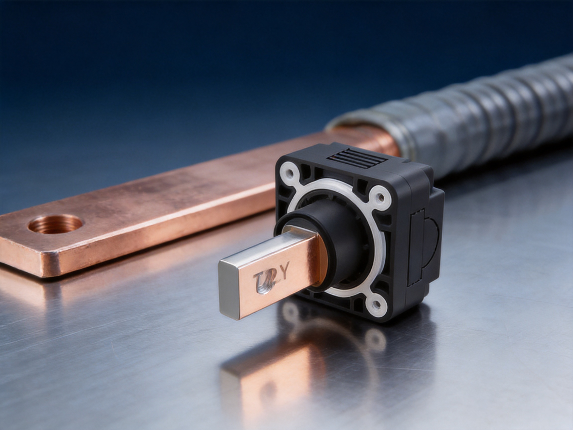
The conductor is manufactured from T2Y pure copper and finished with nickel plating. Copper provides excellent electrical conductivity and current-carrying capability, while nickel plating improves surface durability and resistance to oxidation and corrosion. The external insulating structure is made from PA66, a technical engineering polymer selected for its mechanical strength, electrical insulation performance, temperature resistance, and flame-retardant capability.
The design supports 20×4 mm copper bars with 50 mm² or 70 mm² cables in one configuration, 25×6 mm busbars with 95 mm² or 120 mm² cables in another, and 30×10 mm busbars with 150 mm² or 185 mm² cables for higher-current applications. Depending on the selected model, rated current options include 200A, 250A, 300A, 350A, 400A, 450A, and 600A.
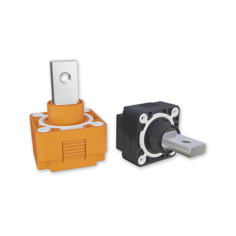
Copper Bar Connector
Core Electrical Advantages
High Conductivity and Low Contact Resistance
The electrical performance of a high-current connector depends not only on the bulk conductivity of its metal parts but also on the quality of the contact interface. A connection with excessive resistance produces voltage drop and heat. As current increases, even a small increase in resistance can create significant power loss because heat generation rises according to the square of the current.
The Copper Bar Connector uses T2Y pure copper as the primary conductor material. This copper grade offers dependable conductivity and is well suited to power transmission applications. The conductor is nickel-plated to protect the contact surface from oxidation, discoloration, and environmental attack. This is particularly valuable in battery storage installations exposed to humidity, temperature cycling, dust, and chemical contaminants.
The specified contact resistance is no greater than 0.5 milliohms when measured at 100 mA. Low contact resistance helps reduce energy loss at the connection point and supports more stable operation under high-current loading. It also reduces the likelihood of localized heating caused by an inconsistent or deteriorating contact surface.
Compared with ordinary unplated copper terminals, the nickel-plated contact surface provides a more durable interface for long-term use. Compared with lower-conductivity metal alternatives, the pure copper conductor can deliver stronger current-carrying performance while helping designers manage thermal rise and conductor size.
1500V DC Rated Voltage
Modern battery energy storage systems increasingly use high-voltage DC architectures to improve transmission efficiency and reduce current for a given power level. However, higher voltage places greater demands on insulation, creepage, clearance, material selection, assembly quality, and environmental protection.
The Copper Bar Connector is specified for a rated voltage of 1500V DC. This rating makes it suitable for many high-voltage battery racks, energy storage cabinets, solar power systems, and DC distribution assemblies. The actual suitability of a connector in a particular system must always be confirmed against the complete design, including operating voltage, transient conditions, pollution degree, spacing requirements, enclosure design, and applicable standards.
The high-voltage capability is supported by a PA66 insulation shell with an insulation resistance greater than 500MΩ and a dielectric strength of 4000V AC. These characteristics help limit leakage current and provide an additional electrical barrier between the conductive path and the surrounding equipment.
Thermal Performance Under High Current
High-current components must be designed as part of a complete thermal system. Conductor cross-section, contact pressure, surface finish, mounting torque, cable termination, enclosure ventilation, ambient temperature, and duty cycle all influence the actual operating temperature.
The connector’s low contact resistance helps reduce heat generation at the joint. The high-conductivity copper conductor supports efficient current transfer, while the available current configurations allow the user to select a suitable product according to busbar and cable dimensions. The operating temperature range of -40°C to 125°C provides a broad design margin for many industrial and energy applications.
Although the connector is designed for demanding current levels, correct installation remains essential. The specified M8 or M10 mounting screws must be tightened to the recommended torque, and the connected busbar and cable must be properly aligned. Incorrect torque, contamination, insufficient contact area, or mechanical stress on the cable can increase resistance and reduce the expected thermal performance.
Insulation, Safety, and Environmental Protection
PA66 Insulation Shell
The insulation shell is manufactured from PA66, a widely used engineering polymer for electrical and mechanical components. PA66 offers a combination of mechanical strength, dimensional stability, electrical insulation, and resistance to elevated temperatures. These properties make it suitable for protective housings and terminal components used in industrial power equipment.
The shell is designed to isolate the conductive copper element from nearby metal structures, wiring, and enclosure surfaces. It also helps reduce the risk of accidental contact during installation and service. In high-voltage battery systems, a well-designed insulation barrier is essential because an unintended conductive path can cause arcing, equipment damage, or serious safety hazards.
4000V AC Dielectric Strength
The specified dielectric strength is 4000V AC. This value indicates the electrical withstand capability of the insulation under a defined test condition. Dielectric strength testing is commonly used to identify defects, weak insulation, contamination, or inadequate separation between conductive and non-conductive areas.
Dielectric performance should be considered together with installation conditions. The connector should be installed inside a system that maintains appropriate spacing, protects against sharp edges, and prevents conductive debris or moisture from accumulating around high-voltage parts. The connector provides an important insulation function, but it is not a substitute for complete system-level insulation engineering.
UL94 V-0 Flame Retardancy
The PA66 insulation material is specified as UL94 V-0 flame retardant. Flame-retardant performance is an important consideration in battery systems and electrical enclosures, where high fault currents, overheated conductors, or adjacent component failures may create elevated fire risk.
A V-0 classification indicates that the material is designed to limit burning duration and reduce the likelihood of sustained flaming under the relevant test method. This contributes to a safer component design and helps limit the spread of fire within an electrical assembly. As with all material classifications, the final performance depends on the specific material grade, wall thickness, production quality, and overall system construction.
IP67 Protection
The connector has an IP67 protection rating. The first digit indicates protection against dust ingress, while the second digit indicates protection against temporary immersion in water under specified test conditions. This level of protection is valuable for outdoor energy storage stations, solar installations, mobile power equipment, industrial cabinets, and other applications exposed to dust or water.
IP67 protection can reduce the risk of moisture-related corrosion, insulation degradation, and conductive contamination. However, the rating applies to the properly assembled connector. Cable interfaces, mounting surfaces, seals, and enclosure openings must be installed correctly to preserve the intended protection level.
Compared with exposed terminal blocks or unsealed bolted joints, an IP67-rated connector can provide better resistance to environmental conditions and reduce the maintenance burden. It is particularly useful where equipment cannot be located in a fully controlled indoor environment.
Mechanical Design and Installation Flexibility
Wall-Mount Construction
The wall-mount format allows the connector to be fixed directly to a panel, battery cabinet wall, distribution enclosure, or structural mounting plate. This creates a stable connection point and helps prevent the cable or busbar from carrying unnecessary mechanical loads.
Wall mounting also improves the organization of high-current wiring. Cables can be routed into a defined termination area, while busbars can be positioned with repeatable spacing. In battery cabinets containing multiple modules, a consistent mounting pattern can simplify assembly and improve service access.
The connector’s single-core structure allows designers to install each polarity independently. This can help maintain electrical separation between positive and negative conductors and provides greater flexibility when adapting the product to different enclosure layouts.
Standardized Fasteners and Torque Control
For the 200A and 250A configuration, the specified mounting screws include M8 with a recommended torque of 12N·m and M4 with a recommended torque of 2N·m. Higher-current configurations use M10 with a recommended torque of 30N·m together with M4 at 2N·m.
Torque control is important because the connection must maintain adequate contact pressure without damaging the conductor, thread, insulation shell, or mounting structure. Under-tightening may result in increased contact resistance and vibration-related loosening. Over-tightening may deform components or damage the threaded interface.
Production and maintenance teams can use the specified torque values as part of a standardized work instruction. Torque verification, visual inspection, and electrical testing can then be incorporated into the quality-control process for the complete battery system.
Multiple Busbar and Cable Configurations
A major advantage of the product family is its compatibility with different conductor dimensions. The available configurations allow the same basic connection concept to be applied across a range of current levels and cable sizes.
| Configuration | Rated Current Options | Compatible Busbar | Compatible Cable Size | Mounting Arrangement |
| Standard high-current model | 200A / 250A | 20×4 mm | 50 mm² / 70 mm² | M8 at 12N·m; M4 at 2N·m |
| Intermediate high-current model | 300A / 350A | 25×6 mm | 95 mm² / 120 mm² | M10 at 30N·m; M4 at 2N·m |
| Large high-current model | 400A / 450A / 600A | 30×10 mm | 150 mm² / 185 mm² | M10 at 30N·m; M4 at 2N·m |
The table presents the available product configurations based on the supplied technical information. Final selection should be confirmed with the manufacturer according to the target current, cable construction, installation orientation, ambient temperature, duty cycle, and applicable certification requirements.
Product Specification Summary
| Product type | Single-core wall-mount copper bar connector |
| Primary application | Energy storage, high-voltage battery, power distribution, solar power, electric vehicle, and industrial systems |
| Insulation material | PA66 |
| Conductor material | T2Y pure copper with nickel plating |
| Number of cores | Single-core |
| Rated voltage | 1500V DC |
| Rated current range | 200A to 600A, depending on configuration |
| Contact resistance | ≤0.5mΩ at 100mA |
| Insulation resistance | >500MΩ |
| Dielectric strength | 4000V AC |
| Protection rating | IP67 |
| Flame-retardant rating | UL94 V-0 |
| Operating temperature | -40°C to 125°C |
| Busbar compatibility | 20×4 mm, 25×6 mm, and 30×10 mm configurations |
| Cable compatibility | 50 mm², 70 mm², 95 mm², 120 mm², 150 mm², and 185 mm² configurations |
The combination of electrical, mechanical, and environmental specifications makes this connector suitable for both standardized product platforms and customized energy storage projects. System designers can match the conductor size and current class to the power requirements of each battery cabinet or distribution branch.
Advantages Compared with Conventional Connection Methods
Compared with Bare Bolted Busbar Joints
A traditional busbar joint may consist of a bare copper bar, a cable lug, bolts, washers, and separate insulation materials. While this approach can be effective when carefully engineered, it may require more assembly steps and more attention to insulation protection. Exposed metal surfaces can also be vulnerable to oxidation, accidental contact, and contamination.
The Copper Bar Connector integrates a protected conductor and insulating structure into one product. Its IP67 enclosure helps shield the connection from dust and water, while the PA66 shell provides a defined insulation barrier. This can improve assembly consistency and reduce the need for additional protective covers or improvised insulating materials.
Compared with Unplated Copper Terminals
Unplated copper can provide good conductivity, but its surface may oxidize over time depending on humidity, temperature, contaminants, and electrical loading. Oxidation can affect contact stability and increase resistance at the interface.
The nickel-plated copper conductor offers improved resistance to surface corrosion and environmental degradation. Nickel plating also provides a hard, durable contact surface that can be advantageous during repeated handling and assembly. The result is a more stable connection interface for applications where long service life and predictable electrical performance are important.
Compared with Lower-Current Terminal Products
Many general-purpose terminal products are designed for low- or medium-current wiring and may not be suitable for high-voltage battery systems. Their insulation materials, conductor dimensions, fasteners, and thermal characteristics may not support the demands of 1500V DC or several hundred amperes.
The Copper Bar Connector is designed specifically around high-current and high-voltage requirements. Its copper conductor, multiple busbar sizes, high dielectric strength, low contact resistance, and robust temperature range provide a stronger foundation for energy storage and power distribution applications.
Compared with Non-Sealed Connection Components
Non-sealed connectors may require installation inside a highly controlled enclosure to avoid exposure to moisture, dust, or chemical contaminants. In outdoor or semi-outdoor systems, additional enclosure protection can increase project cost and installation complexity.
With IP67 protection, the Copper Bar Connector offers a more resistant connection platform for harsh environments. It does not eliminate the need for correct system enclosure design, but it can provide an additional level of protection at the connection point and support more flexible equipment placement.
Applications in Energy Storage Systems
Battery Energy Storage Cabinets
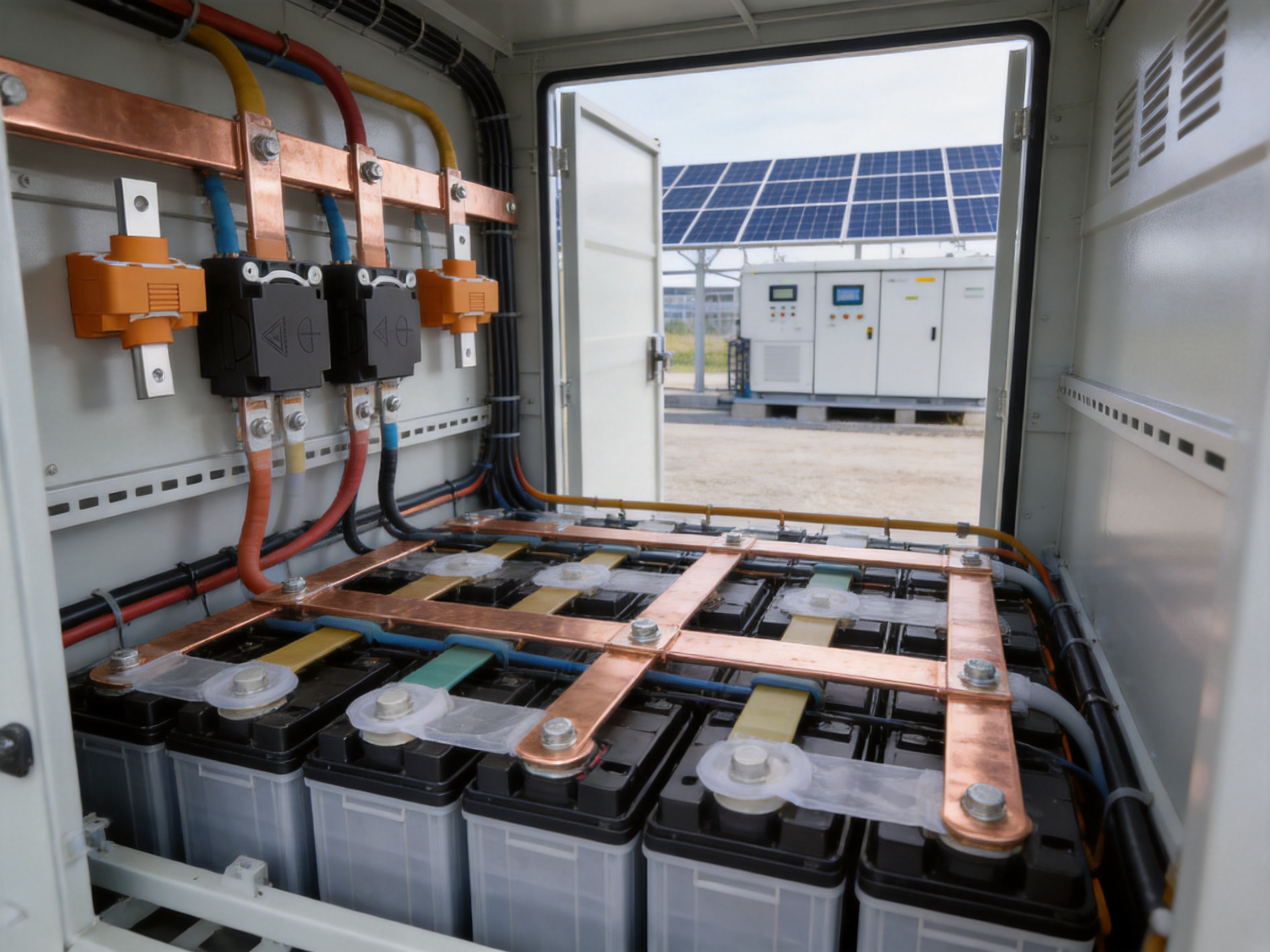
Battery energy storage cabinets contain multiple battery modules, busbars, fuses, contactors, disconnect devices, and power conversion interfaces. High-current connectors are required to join these elements while maintaining insulation and serviceability.
The Copper Bar Connector can be used at module outputs, cabinet busbar transitions, DC collection points, and connections to external power cables. Its wall-mount form helps maintain organized cable routing and can simplify the interface between internal busbars and external system wiring.
In a cabinet design, the selected current rating should reflect continuous current, peak current, allowable temperature rise, operating duty cycle, and ambient conditions. If multiple racks operate in parallel, the designer must also evaluate current sharing, fault current, protective-device coordination, and the mechanical strength of the complete busbar system.
High-Voltage Battery Packs
High-voltage battery packs for electric vehicles, commercial vehicles, industrial vehicles, and mobile equipment require compact yet reliable conductive interfaces. The connector’s insulated single-core design can be used for positive or negative high-current paths where space, insulation, and environmental durability are important.
The operating temperature range of -40°C to 125°C supports a wide range of vehicle and equipment environments. Nevertheless, vehicle designers must consider vibration, shock, thermal cycling, coolant exposure, electromagnetic compatibility, crash safety, and the applicable automotive qualification requirements before approving a component for production use.
Solar Power Generation Systems
Solar power installations often include battery storage, inverters, DC combiner equipment, and high-current distribution points. These systems may be installed outdoors and exposed to rain, dust, sunlight, temperature fluctuations, and condensation.
The connector’s IP67 protection and wide temperature range make it a practical option for protected DC connection points in solar and storage systems. Nickel-plated copper helps maintain surface durability, while the flame-retardant PA66 shell provides an additional safety feature within electrical enclosures.
Industrial Power Distribution
Industrial control cabinets, power supplies, charging equipment, telecommunications power systems, and automated production equipment may all require high-current DC connections. The connector can support these systems where a fixed, insulated, and serviceable busbar-to-cable interface is needed.
Its compatibility with common busbar and cable dimensions can help manufacturers standardize their connection architecture across different equipment models. Standardization can reduce assembly variation, simplify spare-parts management, and make maintenance procedures easier to document.
Manufacturing Strengths and Engineering Capabilities
Zhejiang Zhongyan New Energy Co., Ltd. is a high-tech enterprise focused on conductive components and new energy electrical connection solutions. Its product scope includes high-voltage electrical copper foil soft connections, special-shaped soft connections, battery soft connections, and other precision conductive components used in power transmission, new energy vehicles, rail transit, communication, and energy storage.
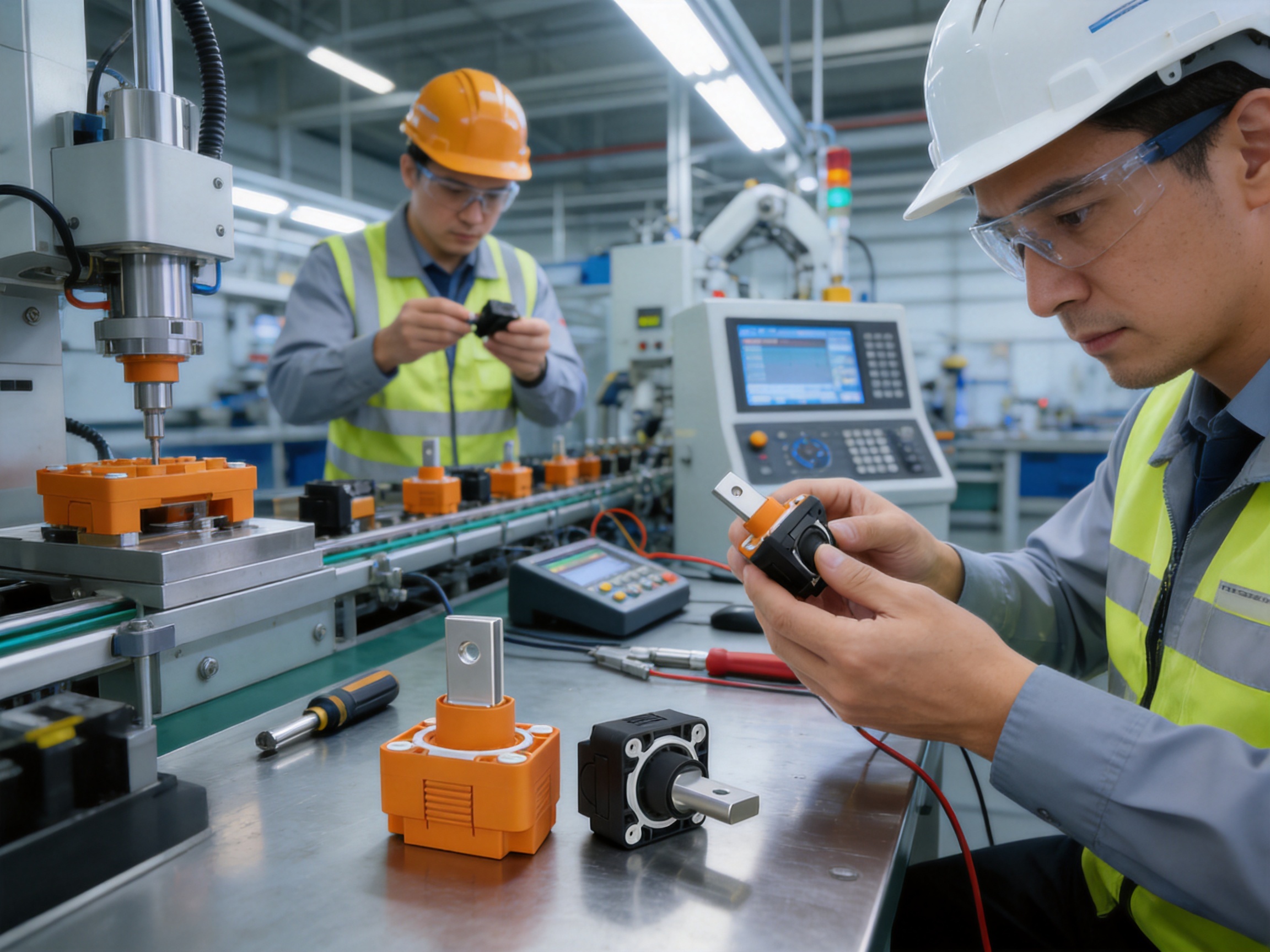
The company combines engineering design, research and development, precision manufacturing, testing, and solution support. This integrated capability is important for high-current connectors because performance depends on the interaction of multiple disciplines. Copper material selection, plating quality, insulation molding, mechanical tolerances, contact geometry, thermal behavior, and final inspection must all be controlled as part of one coordinated process.
Material Engineering
Material selection begins with the electrical and environmental requirements of the application. T2Y pure copper is selected for the conductive path because it combines strong conductivity with suitable mechanical formability. Nickel plating is applied to improve surface durability and corrosion resistance. PA66 is used for the insulation shell because it provides mechanical strength and electrical insulation in a wide operating temperature range.
Material control may include incoming inspection, supplier verification, dimensional checks, surface inspection, and electrical testing. Consistent raw materials help reduce variation in resistance, mechanical fit, plating appearance, and molding performance.
Precision Forming and Machining
The copper conductor must be formed and machined accurately to create a reliable interface with the busbar, cable, and mounting hardware. Dimensional accuracy affects contact area, bolt alignment, pressure distribution, and installation repeatability.
Precision equipment and experienced technical personnel help ensure that the conductor maintains the intended geometry throughout production. Stable tooling and process parameters are particularly important when products are manufactured in different current classes, since larger conductors and higher-current interfaces may require different forming and machining conditions.
Nickel-Plating Process Control
Nickel plating is more than a cosmetic finish. The plating layer must provide consistent coverage over the working surfaces and remain firmly bonded to the copper substrate. Process control can involve surface preparation, plating-bath management, thickness monitoring, visual inspection, and adhesion verification.
A stable plating process helps protect the contact interface from environmental attack and supports repeatable electrical performance. It also reduces the risk that oxidation or surface contamination will increase contact resistance over the service life of the product.
Injection Molding and Insulation Integration
The PA66 shell must fit accurately around the conductive element while maintaining the required insulation distances and mechanical strength. Injection molding conditions, mold design, material drying, dimensional shrinkage, and cooling control all influence the final quality of the insulating component.
The integration of the conductor and shell must be carefully controlled to avoid voids, cracks, deformation, incomplete filling, or unwanted movement of the conductive part. A consistent molding process supports the electrical withstand capability, environmental sealing, and mechanical stability of the finished connector.
Testing and Verification
High-voltage and high-current components require verification at multiple stages. Typical quality-control activities may include dimensional inspection, appearance inspection, contact resistance testing, insulation resistance testing, dielectric withstand testing, torque verification, and environmental evaluation.
For an IP67-rated component, sealing and assembly quality are especially important. The connector must be inspected to ensure that the protective structure is complete and that mating or cable interfaces are correctly prepared. Depending on the project, additional tests may include temperature cycling, vibration, humidity exposure, salt spray, mechanical endurance, and long-duration current loading.
The company’s experience in conductive component development and battery connection systems supports a process-oriented approach to product reliability. By combining design capability with manufacturing and verification resources, it can respond to customer requirements involving dimensions, current levels, connection geometry, insulation, and installation structure.
Research and Development Background
The company was established in 2022 and has developed a technical foundation in new energy precision components, including battery soft connections. Its development activities cover materials science, precision machining, testing, verification, and integrated battery connection systems.
According to the supplied company information, the company has independently developed polymer diffusion welding and laser technology patents for producing components with ultra-low internal resistance and high reliability. These technologies are relevant to advanced conductive connections because welding quality and heat-affected-zone control can influence resistance, mechanical strength, flexibility, and long-term durability.
The company has also supplied products to leading enterprises including BYD, CATL, and Jaguar, according to the provided information. Such customer experience indicates familiarity with demanding quality expectations, engineering communication, production consistency, and project-based customization. Specific qualification status, certifications, and customer approvals should be confirmed directly for each product and application.
The company is expanding its research and development system to connect battery cell technology with connection-system design. This direction is significant because future energy storage products require more than individual components. They increasingly require integrated solutions that optimize electrical performance, thermal behavior, packaging efficiency, production automation, and service safety.
Customization and OEM Support
Energy storage projects frequently involve non-standard dimensions, specialized enclosure layouts, different cable exits, unique busbar arrangements, or customer-specific insulation requirements. A connector supplier with design and manufacturing capabilities can provide more value than a distributor offering only standard catalog parts.
Customization may involve conductor dimensions, busbar interface geometry, cable compatibility, mounting-hole positions, insulation-shell shape, marking, packaging, plating specifications, or current-class optimization. The product can serve as a starting platform for an application-specific design rather than being limited to one fixed configuration.
A typical OEM development process begins with the customer’s electrical and mechanical requirements. These may include rated voltage, continuous and peak current, busbar thickness, cable cross-section, installation direction, enclosure dimensions, operating temperature, environmental exposure, insulation requirements, and expected service life.
The engineering team can then review the connection concept, recommend a suitable conductor size and mounting structure, create drawings or samples, and conduct prototype verification. Design-for-manufacturing review helps ensure that the final product can be produced consistently and economically at the required volume.
For large projects, quality documentation may include material certificates, inspection reports, dimensional records, electrical test results, process-control documents, and traceability information. Customers should discuss these requirements early in the development process so that the production and testing systems can be aligned with the project’s quality plan.
Installation Recommendations
Before installation, verify that the selected connector matches the busbar dimensions, cable size, rated current, rated voltage, polarity arrangement, and environmental conditions of the application. Do not force a busbar or cable into a connector that is not designed for its dimensions.
Make sure the copper contact surfaces are clean and free from oil, dust, burrs, oxidation, or conductive debris. Cable ends should be prepared according to the applicable termination procedure. Busbars should be flat, properly supported, and aligned with the connector interface.
Install the connector on a sufficiently rigid mounting surface. The panel or support structure should withstand the mechanical forces generated by cable weight, vibration, short-circuit events, and installation torque. Avoid allowing the connector to act as the sole support for a heavy or moving cable.
Tighten M8, M10, and M4 fasteners according to the specified torque values using a calibrated torque tool. Record torque values when required by the project quality plan. Incorrect torque is one of the most common causes of unstable high-current connections.
After installation, inspect the joint for correct seating, alignment, damaged insulation, exposed conductive surfaces, and signs of mechanical stress. Perform insulation resistance and dielectric withstand tests according to the system’s safety procedure. Where appropriate, conduct a current-load or thermal inspection to confirm that the connection remains within the required temperature limits.
During maintenance, isolate and verify the absence of hazardous voltage before opening the enclosure or touching the connector. Inspect for discoloration, overheating, looseness, corrosion, damaged seals, and cracks in the insulation shell. Any component showing evidence of electrical or mechanical damage should be evaluated and replaced according to the equipment maintenance procedure.
Selection Guide for System Designers
Selecting the Current Class
The rated current should not be selected solely from the nominal battery current. Designers should consider continuous current, short-term overload, ambient temperature, enclosure temperature, installation orientation, cable bundling, duty cycle, and thermal derating. If a system operates near the upper current limit for long periods, a higher-current configuration may provide greater thermal margin.
Selecting the Busbar Interface
Match the connector to the exact busbar width and thickness. The available interfaces include 20×4 mm, 25×6 mm, and 30×10 mm arrangements. The busbar must be manufactured to suitable dimensional tolerances and must not be bent or twisted during installation.
Selecting the Cable Size
Available cable compatibility includes 50 mm², 70 mm², 95 mm², 120 mm², 150 mm², and 185 mm² configurations. The correct cable size depends on current, insulation temperature rating, installation method, allowable voltage drop, fault conditions, and applicable electrical codes. Cable flexibility and bending radius should also be considered when planning the enclosure layout.
Considering Environmental Conditions
The IP67 rating and -40°C to 125°C operating temperature range support challenging conditions, but the complete assembly must be evaluated. Designers should consider condensation, salt exposure, chemicals, ultraviolet radiation, vibration, thermal cycling, and the possibility of water collecting around cable interfaces or mounting points.
Confirming Standards and Certifications
Product specifications should be reviewed against the standards required for the target market and application. Energy storage systems, electric vehicles, industrial equipment, and solar installations may have different certification and testing requirements. The customer should request current technical documentation and confirm the relevant approval scope before mass production or field installation.
Quality, Reliability, and Lifecycle Value
The value of a high-current connector is measured over its entire service life, not only by its purchase price. A low-cost component that develops high resistance, corrosion, insulation damage, or mechanical looseness can create much higher costs through energy loss, downtime, thermal failures, maintenance, and replacement.
The Copper Bar Connector supports lifecycle value through several coordinated design features. The pure copper conductor helps provide efficient current transfer. Nickel plating protects the contact surface. PA66 insulation improves mechanical and electrical protection. IP67 construction supports environmental resistance. Standard mounting hardware assists installation control. Multiple current and conductor configurations help reduce the need for unsuitable adaptations.
Stable electrical contact also supports system efficiency. In a large battery installation with many high-current connection points, small losses at each joint can accumulate. Maintaining low resistance across the connection network can contribute to lower heat generation and more efficient power delivery.
Reliability also depends on manufacturing consistency. A product manufactured with controlled materials, stable tooling, defined inspection procedures, and traceable quality records is more likely to perform consistently across different production lots. This is especially important for energy storage manufacturers that build thousands of cabinets or battery packs with repeated connection structures.
Why This Connector Is Suitable for Modern Energy Infrastructure
Energy infrastructure is becoming more electrified, distributed, and power-dense. Battery storage systems must move large amounts of energy through compact cabinets while operating safely under variable temperatures and demanding duty cycles. Solar installations and electric vehicle systems add further requirements for outdoor protection, high-voltage insulation, mechanical stability, and long-term serviceability.
The Copper Bar Connector addresses these requirements through an integrated high-current design. It is not simply a piece of copper or a general-purpose terminal. It is a protected interface intended for the connection conditions found in battery and power systems.
Its product architecture also supports platform development. Equipment manufacturers can use the 20×4 mm, 25×6 mm, and 30×10 mm busbar options across different system power classes. This can support common design rules while allowing current capacity and cable size to increase as the equipment platform grows.
The connector is also aligned with the trend toward safer and more serviceable battery equipment. A protected, wall-mounted, single-core terminal can help separate conductive paths, organize wiring, reduce accidental-contact risk, and make inspection more systematic.
Frequently Asked Questions
What is the main purpose of the Copper Bar Connector?
It is designed to provide a protected, high-current connection between a copper busbar and a cable or related conductive assembly. It is intended for energy storage batteries, high-voltage battery packs, solar power systems, electric vehicles, and industrial power equipment.
What voltage can the connector handle?
The specified rated voltage is 1500V DC. The complete system must still be designed with appropriate insulation spacing, enclosure protection, overcurrent protection, and safety procedures.
What current ratings are available?
Depending on the selected configuration, rated current options include 200A, 250A, 300A, 350A, 400A, 450A, and 600A. The correct rating depends on the busbar, cable size, ambient temperature, duty cycle, and system design.
Which busbar sizes are compatible?
The available configurations support 20×4 mm, 25×6 mm, and 30×10 mm copper bars. Customers should confirm the exact connector model before ordering.
Which cable sizes can be used?
Depending on the connector configuration, compatible cable sizes include 50 mm², 70 mm², 95 mm², 120 mm², 150 mm², and 185 mm².
Why is the copper conductor nickel-plated?
Nickel plating helps protect the copper surface against oxidation and corrosion. It also creates a durable contact surface that can support more stable electrical performance in demanding environments.
What insulation material is used?
The insulation shell is made from PA66. It provides mechanical protection, electrical insulation, temperature resistance, and UL94 V-0 flame-retardant performance according to the supplied specifications.
Is the connector suitable for outdoor installation?
The IP67 rating and operating temperature range of -40°C to 125°C make it suitable for many outdoor and harsh industrial applications. Correct assembly and system-level environmental protection are necessary to maintain the intended performance.
What is the specified contact resistance?
The specified contact resistance is no greater than 0.5 milliohms when measured at 100 mA.
What is the insulation resistance?
The specified insulation resistance is greater than 500MΩ.
What dielectric strength is specified?
The connector is specified with a dielectric strength of 4000V AC.
What mounting screws are used?
The standard 200A and 250A configuration uses M8 and M4 screws, with recommended torques of 12N·m and 2N·m respectively. Higher-current configurations use M10 and M4 screws, with recommended torques of 30N·m and 2N·m respectively.
Can the connector be customized?
Customization may be available for conductor dimensions, insulation-shell geometry, busbar interface, cable compatibility, mounting arrangement, marking, plating, and other project requirements. Customers should provide complete electrical and mechanical specifications for an engineering review.
What industries can use this product?
Typical industries include energy storage, electric vehicles, solar power generation, power distribution, industrial automation, rail transit, communication power systems, and battery manufacturing.
Does the connector replace system-level safety design?
No. The connector contributes to electrical insulation, environmental protection, and connection reliability, but the complete equipment must still include suitable fuses, disconnect devices, contactors, grounding, spacing, enclosure design, monitoring, and maintenance procedures.
Conclusion
The Copper Bar Connector is a high-current, high-voltage connection component developed for the practical demands of modern battery and energy infrastructure. Its T2Y pure copper conductor provides an efficient current path, while nickel plating improves surface durability and corrosion resistance. The PA66 insulation shell provides high insulation resistance, 4000V AC dielectric strength, and UL94 V-0 flame-retardant performance. IP67 protection and a -40°C to 125°C operating range further support use in harsh indoor and outdoor environments.
With configurations covering 200A to 600A, compatibility with several copper busbar dimensions and cable sizes, and standardized mounting hardware, the product provides design flexibility for battery storage cabinets, high-voltage battery packs, solar power systems, electric vehicles, and industrial power equipment.
Its competitive advantages extend beyond the component specifications. The product is supported by a manufacturer focused on new energy conductive components, precision connection technology, material engineering, manufacturing control, testing, and customized OEM development. The company’s experience in battery soft connections, polymer diffusion welding, laser technology, and integrated battery connection systems provides a strong foundation for customers seeking reliable and application-specific electrical connection solutions.
For projects where high current, high voltage, environmental protection, installation consistency, and long-term reliability are essential, the Copper Bar Connector offers a practical and scalable connection platform. Final product selection should be confirmed through detailed electrical, mechanical, thermal, environmental, and certification reviews, ensuring that the selected model is correctly matched to the complete system.
References
IEC 60529, Degrees of Protection Provided by Enclosures, IP Code.
UL 94, Standard for Tests for Flammability of Plastic Materials for Parts in Devices and Appliances.
IEC 60664-1, Insulation Coordination for Equipment Within Low-Voltage Systems.
IEC 62477-1, Safety Requirements for Power Electronic Converter Systems and Equipment.
IEC 62933 Series, Electrical Energy Storage Systems.
ASTM B187, Standard Specification for Copper, Bus Bar, Rod, and Shapes.
Manufacturer-supplied technical specifications for Copper Bar Connector configurations.
Manufacturer-supplied company information regarding new energy conductive components, battery connection systems, manufacturing capabilities, and research and development activities.
Product: Copper Bar Connector

Driven by the development of new energy and aiming for "zero carbon".
Copyright © Zhejiang Zhongyan New Energy Co., Ltd. All Rights Reserved.
