 English
 Español

Wind and Solar Composite Laminated Busbars: High-Performance Power Distribution for Renewable Energy Systems
The rapid expansion of wind power, solar generation, battery storage, and intelligent microgrids is changing the design requirements for electrical power systems. Renewable energy equipment must operate efficiently under high electrical loads, frequent power conversion, temperature variation, vibration, humidity, and demanding installation conditions. At the same time, manufacturers of inverters, converters, power conversion systems, and energy storage equipment are seeking more compact internal connections with lower electrical losses and better electromagnetic performance.
Composite laminated busbars provide a practical solution to these challenges. By integrating conductive copper layers, high-quality insulation, precision spacing, and application-specific connection points into one engineered assembly, a laminated busbar can replace multiple conventional cables, loose copper bars, and complex wiring arrangements. The result is a shorter current path, improved mechanical stability, better thermal behavior, reduced stray inductance, and more efficient use of cabinet space.
The Wind and Solar Composite Laminated Busbar is developed for demanding renewable energy applications, including onshore and offshore wind converters, photovoltaic central inverters, string inverters, energy storage power conversion systems, microgrid equipment, and other high-power electronic circuits. It supports current ratings from approximately 100 A to 6000 A, while its geometry, insulation system, plating, mounting holes, and terminal configuration can be customized to match a customer's equipment.
With precision manufacturing, controlled insulation processes, advanced testing, and extensive experience in conductive components, Zhejiang Zhongyan New Energy Co., Ltd. supplies tailored busbar assemblies for reliable power transmission and distribution. The company's capabilities cover product design, material selection, manufacturing, inspection, verification, and application support, allowing the laminated busbar to be treated as an integrated electrical component rather than a basic piece of conductive metal.
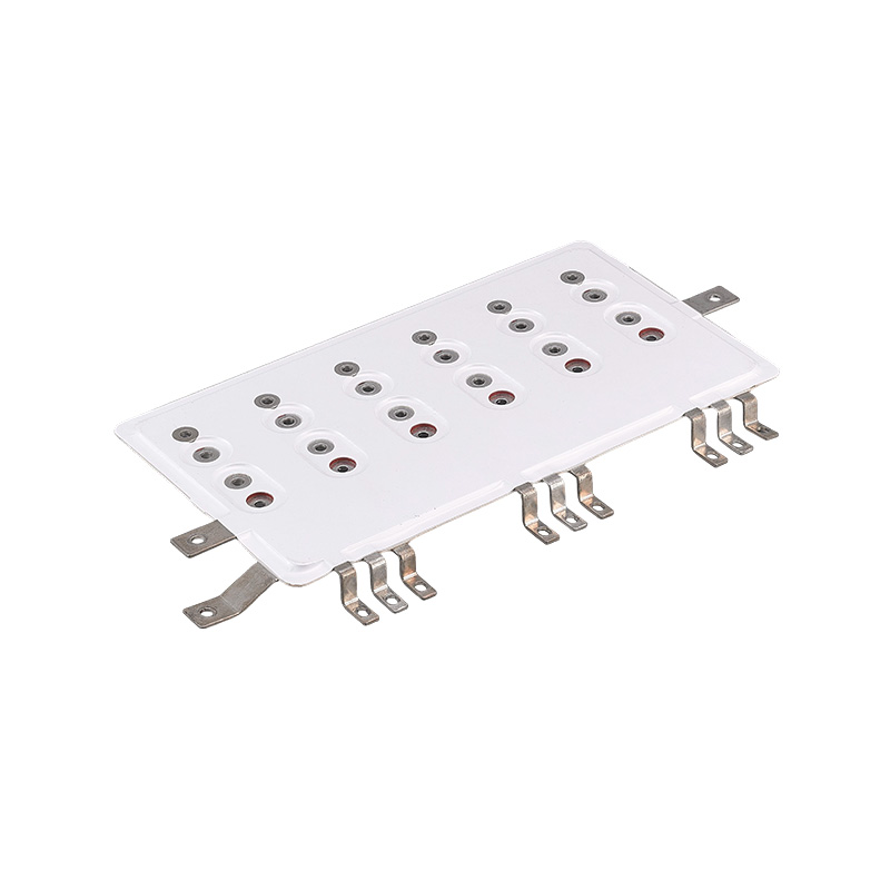
Wind & Solar Composite Laminated Busbar
1. Why Laminated Busbars Matter in Renewable Energy Equipment
Renewable energy systems use power electronics to convert, control, store, and distribute electrical energy. A wind turbine may generate variable-frequency power that must be converted into grid-compatible electricity. A photovoltaic array produces direct current that must pass through a central or string inverter before being delivered to an alternating-current network. An energy storage system repeatedly transfers power between battery packs and the grid through a power conversion system.
These conversion processes involve high current, fast switching, and significant electrical and thermal stress. Conventional cable assemblies may be suitable for smaller systems, but as power density increases, cables can create several design difficulties. They require substantial bending space, may have uneven current distribution, create larger electromagnetic loops, and involve numerous individual termination points. Their installation can also be labor-intensive, particularly when several parallel conductors are required.
A laminated busbar uses stacked and insulated conductive layers to create a compact, controlled current path. Positive and negative conductors, or multiple phase conductors, can be arranged in a carefully defined structure. The close and consistent spacing between layers reduces loop area and helps lower parasitic inductance. Connection points can be positioned to align directly with semiconductor modules, capacitors, switches, filters, terminals, or other major electrical components.
For renewable energy equipment, this structure can improve the relationship between the electrical, mechanical, and thermal design of the system. A busbar can be shaped around available cabinet space, integrated with mounting features, and manufactured with specific terminal locations. This makes it possible to reduce unnecessary conductors and simplify the internal layout of the equipment.
1.1 Managing High Current in Compact Equipment
Wind converters and solar inverters often operate at high current levels. The supplied product family is designed for current capacities ranging from 100 A to 6000 A, depending on the conductor material, cross-sectional design, number of layers, cooling conditions, and application requirements. A properly designed busbar distributes current across a broad conductive surface instead of concentrating it in a small wire or terminal.
The copper plate thickness, width, layer arrangement, connection structure, and surface treatment can all be selected according to the electrical rating. Representative designs include copper plates with thicknesses of 1.5 mm, 2.0 mm, and 2.5 mm. These examples demonstrate that the busbar can be engineered for different current levels and equipment layouts rather than being limited to one standard configuration.
1.2 Reducing Stray Inductance
Stray inductance is a key consideration in high-speed switching circuits. When a semiconductor device switches a large current rapidly, inductance in the current path can generate voltage overshoot, ringing, electromagnetic interference, and additional stress on switching components. Excessive inductance can reduce system efficiency and may require additional snubber components or filtering measures.
The laminated structure places related conductors close together and controls their relative position. The opposing magnetic fields around adjacent current paths can partially cancel one another, helping reduce the effective loop inductance. This low-inductance structure is particularly valuable in inverter DC links, converter power circuits, energy storage PCS equipment, and other circuits where switching speed and voltage stability are important.
Lower stray inductance does not eliminate the need for proper circuit design, grounding, filtering, and protection. However, it gives the system designer a more controlled electrical connection and can support better switching performance. It also helps reduce the risk of unwanted voltage transients caused by long, irregular, or poorly arranged conductors.
2. Product Structure and Engineering Characteristics
A composite laminated busbar normally consists of one or more copper conductors separated by electrical insulation. The copper layers may be bare, plated, or otherwise surface-treated according to the application. Insulating materials are selected for voltage rating, temperature performance, mechanical strength, resistance to environmental conditions, and compatibility with the manufacturing process.
The final assembly can include drilled holes, threaded inserts, press-fit components, formed sections, terminals, flexible transition areas, locating features, and protective edge treatment. Its shape may be flat, stepped, folded, irregular, or three-dimensionally formed to follow the architecture of an inverter or converter.
2.1 Copper Conductors
Copper is widely used for laminated busbars because of its high electrical conductivity, good thermal conductivity, ductility, and suitability for precision fabrication. The conductor thickness and width are determined by current capacity, allowable temperature rise, available space, mechanical requirements, and the expected duty cycle of the equipment.
Representative products use copper plates with thicknesses of 1.5 mm, 2.0 mm, or 2.5 mm. These values are not restrictive limits. Custom thickness, width, shape, hole pattern, and layer count can be developed for a particular application. When required, copper surfaces may be tin-plated to improve solderability, contact stability, corrosion resistance, and compatibility with mating components.
2.2 Insulation System
The insulation system is one of the most important parts of a laminated busbar. It separates adjacent conductive layers, maintains the required dielectric distance, and protects the conductors against accidental contact, environmental exposure, and electrical breakdown. The insulation structure must remain stable during assembly, operation, thermal cycling, and vibration.
Insulation selection depends on the working voltage, test voltage, operating temperature, humidity, contamination level, clearance and creepage requirements, mechanical design, and customer specifications. The busbar manufacturing process is controlled to avoid wrinkles, voids, misalignment, contamination, or damage that could weaken the insulation system.
For high-voltage renewable energy equipment, effective partial discharge control is especially important. Partial discharge can gradually degrade an insulation system when localized electrical stress occurs in small voids, interfaces, or areas of field concentration. Appropriate insulation materials, controlled bonding, suitable edge design, and inspection procedures help reduce the possibility of such defects.
2.3 Surface Treatment
Tin-plated copper is used in several representative designs. Tin plating can provide a stable contact surface and can help protect copper against oxidation. It may also support more consistent electrical contact at terminals and improve compatibility with certain connection methods.
Surface treatment must be matched to the application. Factors include contact pressure, operating temperature, humidity, current level, assembly method, expected service life, and the material used on the mating component. A qualified manufacturing process controls surface cleanliness, coating uniformity, adhesion, and dimensional consistency.
2.4 Precision Connection Features
A laminated busbar is more effective when its connection points are designed together with the customer's power circuit. Hole positions, terminal locations, bolt sizes, contact surfaces, and component interfaces must be produced accurately. Poor alignment can create installation stress, uneven contact pressure, or unnecessary mechanical loading on connected devices.
Precision connection features support error-free installation. They reduce the need for field modification, minimize the risk of connecting conductors in the wrong position, and shorten assembly time. For equipment manufactured in large quantities, consistent hole patterns and repeatable dimensions also simplify production-line fixtures and inspection procedures.
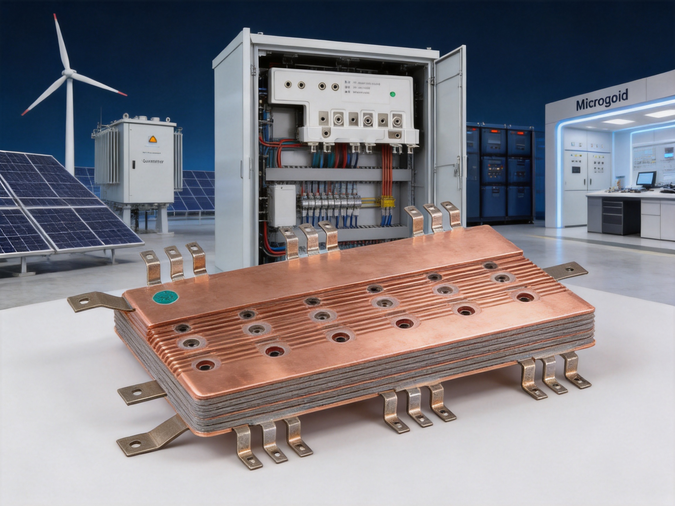
3. Electrical Advantages Compared with Conventional Interconnections
The main advantage of a composite laminated busbar is that it combines electrical conductors and insulation into a controlled, compact assembly. Compared with separate cables or uninsulated copper bars, it can offer a more predictable electrical path and a more organized mechanical structure.
3.1 Lower Inductance and Improved Switching Behavior
In a conventional cable arrangement, the supply and return conductors may be physically separated, creating a larger current loop. The larger the loop area, the greater the potential for parasitic inductance and electromagnetic radiation. A laminated busbar places the relevant conductors in a close, parallel arrangement, which reduces loop area and supports low-inductance operation.
This is particularly useful in DC-link circuits and high-frequency switching paths. Reduced inductance can help limit voltage overshoot during switching transitions, reduce ringing, improve electromagnetic compatibility, and lower stress on power semiconductor devices. It can also support the use of faster switching strategies when the entire circuit has been designed for that operating mode.
3.2 Reduced Electromagnetic Interference
Electromagnetic interference can affect control circuits, communication interfaces, sensors, protection systems, and nearby equipment. In wind and solar power electronics, rapid changes in voltage and current can create common-mode and differential-mode noise. A controlled laminated structure helps reduce the radiating loop area and makes the current path more predictable.
The busbar is not a substitute for a complete electromagnetic compatibility strategy. Shielding, grounding, filtering, enclosure design, switching control, and cable routing remain important. Nevertheless, a low-inductance laminated busbar can contribute to improved EMI performance by keeping high-current paths compact and well defined.
3.3 Improved Current Distribution
A broad copper plate can provide more uniform current distribution than a collection of loosely arranged conductors. This is useful when equipment contains multiple parallel semiconductor modules, capacitors, or output terminals. The busbar design can be optimized so that each connection point has an appropriate electrical path length and cross-sectional area.
Uniform current distribution can reduce localized heating and improve the balance among parallel branches. The actual result depends on conductor geometry, connection resistance, component tolerances, switching behavior, and thermal conditions. For this reason, electrical simulation, prototype testing, and temperature-rise verification are valuable during product development.
3.4 Lower Contact and Assembly Risk
Every additional cable, lug, bolt, and connection point introduces a possible source of resistance variation or assembly error. A custom laminated busbar consolidates multiple connections into one designed component. This can reduce the number of separate operations and lower the likelihood of incorrect routing or incomplete tightening.
Consistent contact geometry also helps improve repeatability during production. When the busbar is designed to fit a specific inverter or converter, technicians can install it according to a defined process rather than manually arranging several flexible conductors in a limited space.
4. Mechanical, Thermal, and Environmental Performance
4.1 Vibration Resistance
Wind power equipment is exposed to vibration from rotating machinery, changing wind loads, gearbox operation, and structural movement. Offshore installations may experience additional mechanical stress from marine conditions, transportation, and platform movement. A busbar used in this environment must maintain its insulation and connection integrity during long-term vibration.
Because a laminated busbar is a structured assembly with defined mounting points, its mechanical behavior can be analyzed and controlled more effectively than a loose group of cables. The design can include support points, reinforced regions, rounded transitions, and suitable fixation areas. These features help reduce movement, rubbing, and stress concentration.
Mechanical validation may include dimensional inspection, assembly checks, vibration testing, thermal cycling, and visual examination after testing. The appropriate test program depends on the equipment category, installation environment, customer requirements, and relevant industry standards.
4.2 Heat Dissipation
Electrical resistance produces heat whenever current flows through a conductor. The amount of heat is affected by copper cross-sectional area, current, contact resistance, ambient temperature, airflow, neighboring components, and duty cycle. In compact power electronics, thermal management is essential because high temperature can accelerate insulation aging and reduce component life.
Copper provides good thermal conductivity, allowing heat to spread across the conductor. The laminated busbar can be designed with suitable surface area, spacing, mounting orientation, and interfaces to cooling structures. In some applications, the busbar may be positioned near forced-air channels, heat sinks, liquid-cooled components, or cabinet ventilation paths.
Thermal design should be validated by measuring temperature rise at expected current, overload, switching frequency, ambient temperature, and installation conditions. Measurements should cover conductor sections, connection points, plated surfaces, insulation interfaces, and nearby components. A suitable design aims to avoid excessive hot spots rather than relying only on average temperature.
4.3 Long-Term Insulation Stability
Renewable energy equipment may operate continuously for many years. The insulation system therefore needs to resist thermal aging, vibration, moisture, contamination, and electrical stress. Material compatibility is important because copper, plating, adhesives, insulating films, fasteners, and surrounding components may expand at different rates as temperature changes.
A robust design considers dielectric strength, creepage distance, clearance, edge conditions, environmental sealing, and the possibility of condensation. Manufacturing controls are equally important. Even a high-quality insulating material can perform poorly if it is contaminated, improperly bonded, damaged during assembly, or installed with inadequate spacing.
4.4 Outdoor and Offshore Applications
Outdoor photovoltaic stations and wind turbines may be exposed to sunlight, rain, dust, salt spray, condensation, and large daily temperature changes. Offshore systems face especially demanding conditions because of humidity and salt-containing atmospheres. The laminated busbar must be integrated into an enclosure and environmental protection strategy suitable for the installation location.
Material selection, plating, insulation, sealing, fastening, and surface protection should be evaluated as one system. The product should be stored, transported, and installed according to procedures that prevent moisture absorption, mechanical damage, and contamination before commissioning.
5. Representative Product Specifications
The following examples illustrate the range of configurations available for renewable energy power circuits. They are representative designs rather than universal limits. Final dimensions, current ratings, insulation structure, dielectric test levels, and partial discharge requirements should be confirmed for each project.
| Representative Design | Dimensions | Copper Plate Thickness | Surface | Voltage Rating | Current Rating | Dielectric Verification |
|---|---|---|---|---|---|---|
| Design A | 530 mm × 450 mm | 2.0 mm | Tin-plated | 1100 V DC | 1000 A | 5 kV DC for 60 seconds, less than 2 mA |
| Design B | 620 mm × 320 mm | 1.5 mm | Tin-plated | 1000 V DC | 300 A | 5 kV DC for 60 seconds, less than 2 mA |
| Design C | 520 mm × 400 mm | 2.5 mm | Tin-plated | 1000 V DC | 1200 A | 3.5 kV DC for 60 seconds, less than 2 mA; partial discharge at 1.2 kV AC, fewer than 10 events |
The dimensions in the table show how laminated busbars can be adapted to different equipment layouts. The 530 mm × 450 mm design, for example, combines a 2.0 mm copper plate with a 1100 V DC voltage specification and a 1000 A current rating. The 620 mm × 320 mm design is more compact in one direction and is rated for 300 A. The 520 mm × 400 mm design uses a thicker 2.5 mm copper plate and supports a 1200 A current rating in its stated configuration.
Dielectric testing verifies the insulation system under a specified test voltage and duration. The measured leakage current must remain within the defined limit. Partial discharge testing provides additional information about localized insulation activity under electrical stress. These tests are important for high-voltage applications because they help identify weaknesses that may not be visible during a basic visual inspection.
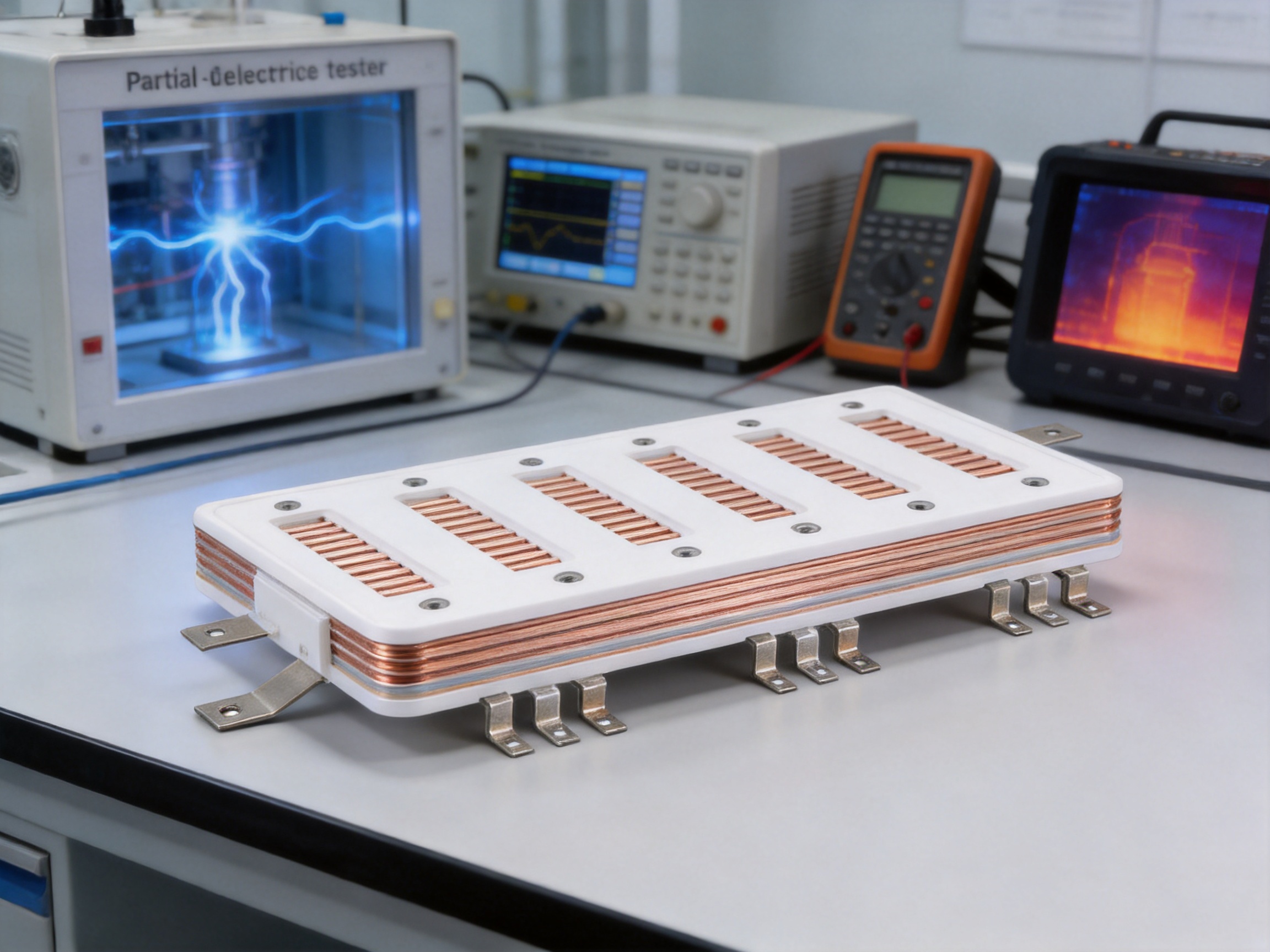
6. Manufacturing Process and Quality Control
The performance of a laminated busbar depends not only on the design but also on the consistency of its manufacturing process. Dimensional accuracy, insulation alignment, surface quality, bonding, plating, hole position, and final electrical performance must be controlled together. Zhejiang Zhongyan New Energy Co., Ltd. combines engineering experience, specialized equipment, production management, and inspection procedures to develop stable and repeatable products.
6.1 Engineering Review and Application Analysis
Manufacturing begins with a review of the customer's electrical and mechanical requirements. Engineers analyze working voltage, current, switching behavior, temperature limits, available space, mounting method, connection points, insulation requirements, environmental conditions, and expected service life.
Three-dimensional product data, two-dimensional drawings, sample assemblies, or equipment interface information may be used during this phase. The engineering team checks whether the proposed conductor arrangement provides sufficient current capacity and whether the insulation system offers suitable clearance and creepage. Mechanical interference with capacitors, semiconductor modules, cooling components, enclosures, and service access areas is also reviewed.
Design for manufacturing is an important part of this stage. A shape that is electrically effective but difficult to form, inspect, or install may create unnecessary production risks. Engineers therefore consider bend radii, tool access, hole tolerances, material handling, bonding areas, plating zones, and inspection references before releasing the design.
6.2 Copper Material Preparation
Copper sheets or plates are prepared according to the approved drawing and material specification. Cutting, blanking, punching, drilling, milling, and forming operations must maintain the required dimensions and edge quality. Burrs and sharp edges can damage insulation or create local electrical stress, so edge treatment is carefully controlled.
For high-current designs, the conductor cross-section must be consistent. Variations in width or thickness can influence resistance, temperature rise, and current distribution. Precision processing helps ensure that the finished busbar matches the calculated electrical and thermal performance.
6.3 Forming and Three-Dimensional Shaping
Many renewable energy busbars are not simple flat plates. They may include steps, offsets, folds, vertical transitions, or multiple connection planes. Forming equipment and controlled tooling are used to create the required shape while limiting deformation and damage.
Forming operations must account for copper ductility, springback, bend radius, hole position, and the relationship between conductive layers. Excessive deformation can reduce dimensional accuracy or stress the insulation. Proper process parameters help maintain the intended geometry throughout assembly.
6.4 Insulation Lamination and Bonding
After conductor preparation, insulating materials are positioned between or around the copper layers. The lamination or bonding process must control temperature, pressure, timing, alignment, and cleanliness. A stable process helps reduce voids, wrinkles, delamination, and displacement of the insulation.
Insulation alignment is especially important around holes, terminals, corners, and outer edges. These areas may experience higher electrical and mechanical stress. The manufacturing process is designed to keep conductive surfaces separated by the specified insulation structure and to prevent unintended exposure.
Where bonding materials are used, their compatibility with copper, plating, insulation, and operating temperature must be evaluated. Adhesive selection and curing conditions can influence long-term stability. Process records and inspection results help establish traceability for critical production batches.
6.5 Plating and Surface Treatment
When tin-plated copper is specified, the surface is prepared and treated according to controlled procedures. Cleaning, activation, plating thickness, adhesion, and appearance are monitored. The objective is to provide a consistent contact surface without compromising dimensional tolerance or contaminating the insulation system.
Plating quality is important at bolted or clamped interfaces. Uneven or damaged plating may influence contact resistance and corrosion behavior. Finished surfaces are inspected for coverage, scratches, discoloration, blistering, and other conditions that could affect electrical performance.
6.6 Precision Drilling and Final Machining
Connection holes and mounting features are produced according to customer drawings. Their position and diameter must be controlled because even a small error can make installation difficult or cause stress on connected components. Reference points and inspection fixtures can be used to verify the final geometry.
After machining, burr removal and cleaning are performed. Metal particles or sharp edges must not remain inside the laminated assembly. Cleaning also helps ensure that insulation surfaces and contact areas are free from oil, dust, and processing residue.
6.7 Inspection and Electrical Testing
Quality control may include incoming material inspection, dimensional verification, visual examination, insulation inspection, plating inspection, contact resistance measurement, dielectric withstand testing, and partial discharge testing when required. Thermal and mechanical tests can be performed during qualification or customer approval programs.
Dielectric withstand testing applies a defined voltage for a specified period to verify that the insulation system can resist electrical stress without breakdown. Representative products are tested at 5 kV DC for 60 seconds or at other specified conditions, with leakage current limits such as less than 2 mA.
Partial discharge testing is used for selected high-voltage designs. A representative configuration specifies partial discharge testing at 1.2 kV AC with fewer than 10 events. The exact test method, measurement sensitivity, acceptance criteria, and test voltage should be agreed upon with the customer and related standards.
Inspection records help connect the finished product with its material batch, process route, test results, and final approval. This traceability is valuable for renewable energy projects where equipment may be deployed across multiple sites and expected to operate for many years.
7. Application Areas
7.1 Wind Power Converters
Wind turbines require power conversion equipment that can handle variable generation and convert it into stable grid power. Laminated busbars can be used in the DC link, power module connection, filter circuit, brake circuit, and other high-current sections of a wind converter.
Onshore wind systems benefit from compact and vibration-resistant connection structures. Offshore systems place even greater emphasis on insulation reliability, corrosion management, compact cabinet design, and long-term serviceability. A custom busbar can be shaped to fit converter cabinets and connect directly with switching devices, capacitors, terminals, and protective components.
7.2 Photovoltaic Central Inverters
Central inverters collect and convert substantial DC power from large photovoltaic fields. Their internal power circuits require high-current conductors with controlled inductance and reliable insulation. A laminated busbar can consolidate positive and negative DC paths, simplify the connection of power modules, and reduce the space required for internal wiring.
The design can also support service access and production consistency. By positioning terminals and mounting points according to the inverter structure, the busbar reduces manual cable routing and helps make assembly more repeatable.
7.3 Photovoltaic String Inverters
String inverters are generally more distributed and compact than central inverters. Their limited internal space makes efficient conductor arrangement particularly important. A custom laminated busbar can integrate several connection points into a compact form while maintaining the required electrical separation.
For string inverter manufacturers, the ability to customize dimensions, hole patterns, insulation, and terminals can help optimize the enclosure and reduce unnecessary assembly components. The busbar can be developed alongside the inverter housing, power modules, capacitors, and cooling arrangement.
7.4 Energy Storage Power Conversion Systems
Battery energy storage systems repeatedly charge and discharge, creating high-current paths between battery racks, DC protection equipment, converters, and grid interfaces. Laminated busbars can be used in the PCS, DC distribution section, battery connection system, and high-current switching circuits.
In these applications, low inductance, temperature control, insulation coordination, and mechanical stability are important. The busbar must also be compatible with the customer's battery architecture, service disconnects, fuses, contactors, pre-charge circuits, and monitoring components.
7.5 Microgrids and Industrial Power Electronics
Microgrids combine distributed generation, storage, loads, and grid connection equipment. Their power circuits may experience frequent operating changes, bidirectional energy flow, and complex switching conditions. A laminated busbar can provide a compact and well-organized connection solution for converters, switchgear, filters, and energy management equipment.
The same principles apply to industrial drives, charging systems, rail power equipment, and other high-power electronic systems. The product is especially suitable when low inductance, high current, compact integration, and reliable insulation are required together.
8. Advantages of a Customized Manufacturing Partner
Not all laminated busbars are interchangeable. A catalog product may not match the electrical, mechanical, thermal, and installation requirements of a particular inverter or converter. A capable manufacturing partner should be able to convert equipment requirements into a manufacturable, testable, and reliable busbar design.
8.1 Integrated Engineering Capability
Zhejiang Zhongyan New Energy Co., Ltd. brings together experienced engineers and technical teams with knowledge of conductive components, precision processing, insulation systems, and new energy applications. The company supports the full product process, from design and development to manufacturing, inspection, and application delivery.
This integrated capability helps reduce communication gaps between design and production. When a product requires a change in hole position, layer spacing, conductor thickness, insulation material, plating, or mounting structure, engineering and manufacturing teams can evaluate the effect as a complete system.
8.2 Experience in New Energy Electrical Connections
The company's broader product expertise includes high-voltage electrical copper foil soft connections, special-shaped soft connections, battery soft connections, and other precision conductive components. This experience is relevant to laminated busbars because both product categories require careful control of conductivity, flexibility or geometry, low resistance, mechanical reliability, and electrical insulation.
Knowledge of battery connection systems and power distribution components also supports the development of busbars for energy storage equipment. The company is expanding its capabilities across battery cells, connection systems, and integrated energy solutions, creating opportunities for coordinated component design.
8.3 Advanced Joining and Manufacturing Technologies
The company uses independently developed polymer diffusion welding and laser technology patents in the production of new energy precision components. These technologies support low internal resistance, strong joining quality, and reliable electrical performance when applied to suitable product structures.
For a laminated busbar, joining and forming methods must be selected according to the copper arrangement, insulation system, terminal design, and required mechanical strength. Advanced processes can help produce specialized shapes and connections that would be difficult to achieve with basic machining alone.
8.4 Consistency and Quality Management
Renewable energy equipment manufacturers require consistent parts for repeat production. Variations in dimensions, plating, insulation, or connection resistance can create assembly difficulties and affect system performance. Modern production and quality management systems help control these variables through standardized process instructions, inspection checkpoints, equipment maintenance, and test records.
Stable production also supports project scalability. Once a laminated busbar design has been validated, repeatable manufacturing allows the customer to use the same component across multiple equipment batches or renewable energy projects.
8.5 Support for OEM and Custom Projects
Custom manufacturing may include prototype development, engineering samples, pilot production, design refinement, and volume manufacturing. The supplier can work from drawings, three-dimensional files, samples, interface dimensions, or application descriptions. This is useful when the busbar must fit an existing enclosure or when the customer is developing a new converter platform.
The goal is not simply to produce a copper plate. It is to deliver a functional component that meets electrical, mechanical, thermal, insulation, installation, and verification requirements. A well-managed customization process can reduce redesign cycles and improve the efficiency of equipment development.
9. Designing a Busbar for Maximum System Value
9.1 Define Electrical Requirements Early
Customers should provide nominal current, peak current, overload duration, operating voltage, switching frequency, expected fault conditions, and duty cycle at the beginning of the design process. These parameters influence conductor thickness, layer arrangement, terminal structure, insulation, and thermal design.
It is also helpful to specify the required inductance range or switching performance target. The busbar geometry can then be optimized together with semiconductor modules, capacitors, gate-drive circuits, filters, and snubbers.
9.2 Coordinate Mechanical Interfaces
Accurate information about enclosure dimensions, mounting surfaces, component locations, fastener types, cable entry points, cooling channels, and maintenance clearances helps avoid interference. The busbar should be reviewed in the complete equipment assembly rather than as an isolated drawing.
Service personnel may need to remove covers, replace fuses, access terminals, or inspect insulation. A compact design should not create unnecessary maintenance difficulties. Correctly positioned mounting points and clear installation references can improve both production efficiency and field service.
9.3 Consider Thermal Conditions
Current rating cannot be evaluated independently from temperature. The same conductor may have different performance depending on ambient temperature, airflow, enclosure size, mounting direction, adjacent components, and duty cycle. Thermal simulation and physical testing should be used to confirm the expected temperature rise.
Connection points deserve particular attention because contact resistance can create localized heat. Bolt torque, contact surface condition, plating, flatness, and mechanical support all influence the result.
9.4 Confirm Insulation Coordination
The working voltage, transient overvoltage, pollution level, altitude, humidity, and material characteristics should be reviewed when selecting insulation distances. Clearances and creepage distances must be appropriate for the equipment and installation environment.
High-voltage testing should be agreed upon before production. If partial discharge control is required, the customer and supplier should define the test voltage, frequency, measurement method, sensitivity, and acceptance level. Clear requirements prevent ambiguity during qualification and final inspection.
9.5 Plan for Production and Installation
A busbar that is easy to install can reduce labor, prevent mistakes, and improve production throughput. Features such as locating holes, polarity markings, asymmetric keying, defined terminal faces, and accessible fasteners can help operators install the part correctly.
The design should also consider packaging and transport. Large busbars need adequate protection against bending, impact, contamination, and moisture. Protective packaging and clear identification help ensure that the component arrives in the same condition in which it passed final inspection.
10. Sustainability and Life-Cycle Benefits
Renewable energy equipment is expected to operate efficiently for long periods. A reliable laminated busbar can contribute to this objective by reducing connection losses, supporting compact power conversion, and helping protect high-value switching components from unnecessary electrical stress.
Replacing multiple cables and separate supports with one integrated component may reduce material use, installation time, and cabinet volume. The exact environmental benefit depends on the complete design, manufacturing process, transport method, and service life. However, a durable busbar that reduces failures and maintenance can support a lower total life-cycle impact.
Copper is also a recyclable material. At the end of equipment life, appropriate recycling processes can recover copper and other materials. Product design should consider disassembly, material identification, and responsible waste handling wherever practical.
11. Quality, Reliability, and Customer Confidence
In renewable energy projects, the cost of an electrical connection failure can extend beyond the replacement part. It may involve equipment downtime, field service, lost generation, difficult access, and damage to associated components. For this reason, reliability must be built into the busbar through design, materials, process control, and verification.
The manufacturer's experience in new energy precision components provides a foundation for this approach. The company has developed products for power transmission and distribution, electric vehicles, rail transit, communication equipment, and energy storage. These sectors require stable electrical performance, precise manufacturing, and consistent quality.
Customers can benefit from a structured qualification process that includes drawing review, material approval, prototype evaluation, electrical testing, thermal assessment, mechanical verification, and production inspection. The specific plan should be tailored to the application, but the principle remains the same: product quality should be demonstrated through measurable evidence.
A reliable supplier also maintains clear communication regarding changes. Any modification to conductor material, insulation, plating, tooling, process parameters, or test conditions should be assessed for its possible effect on performance. Change control helps preserve consistency throughout the product life cycle.
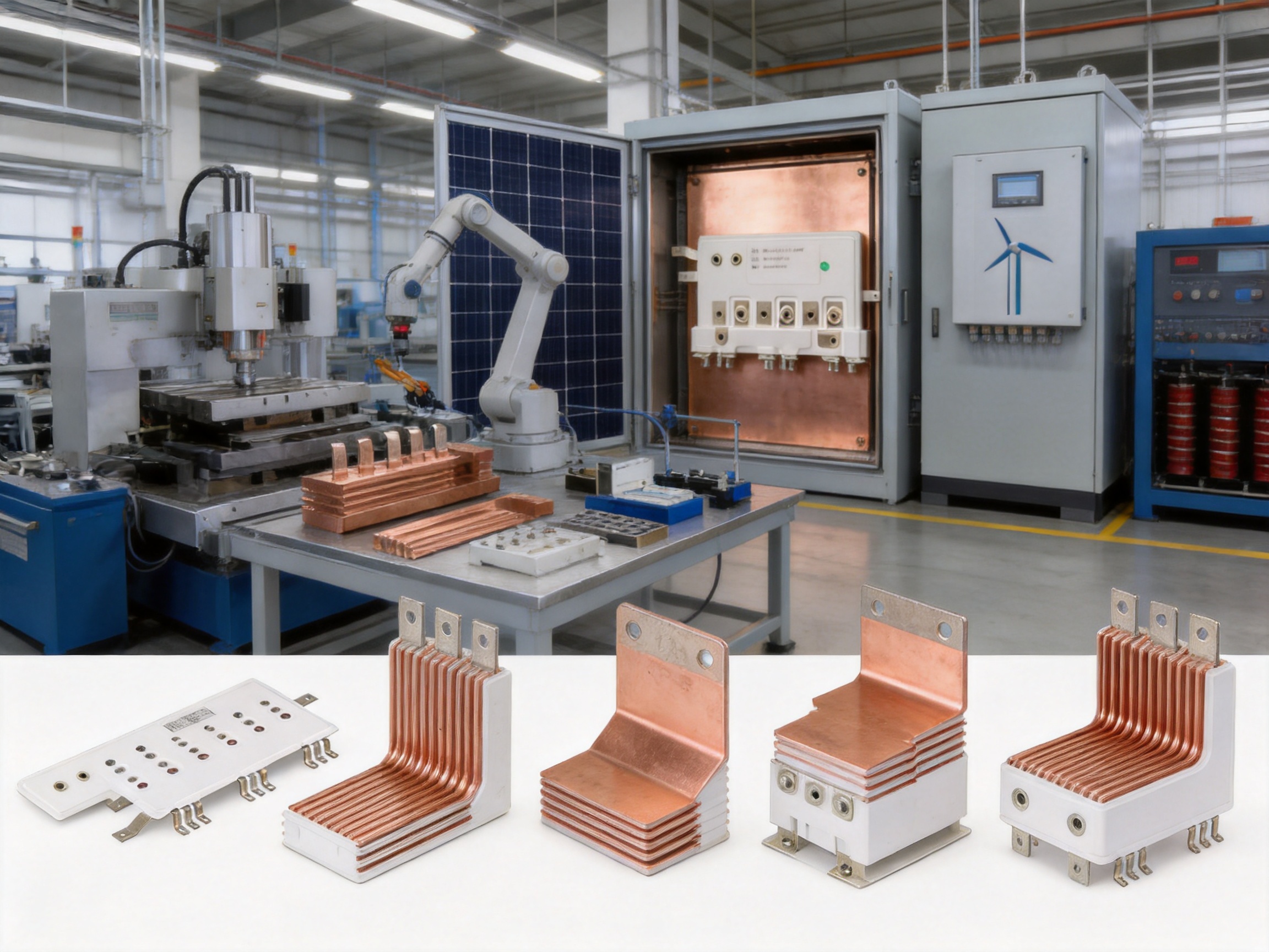
12. Frequently Asked Questions
12.1 What is a composite laminated busbar?
A composite laminated busbar is an insulated assembly made from one or more conductive copper layers and dielectric materials. The layers are arranged in a controlled structure to distribute high current, reduce stray inductance, simplify installation, and provide reliable electrical isolation.
12.2 What current range can the product support?
The product family can be designed for current capacities from approximately 100 A to 6000 A. The actual rating depends on copper thickness, conductor width, number of layers, ambient temperature, cooling conditions, duty cycle, connection structure, and the customer's allowable temperature rise.
12.3 Can the busbar be customized for a specific inverter?
Yes. Dimensions, copper thickness, layer arrangement, insulation, terminal locations, mounting holes, bends, surface treatment, and connection geometry can be customized. Engineering development should be based on the inverter's electrical circuit, enclosure, component locations, thermal conditions, and installation method.
12.4 Why is low inductance important in wind and solar converters?
Low inductance helps reduce voltage overshoot and ringing during rapid switching. It can support better electromagnetic compatibility, reduce stress on power semiconductor devices, and improve the stability of high-current DC-link and converter circuits.
12.5 What surface treatment is available?
Representative designs use tin-plated copper surfaces. Tin plating can support stable electrical contact, improve solderability where applicable, and provide additional protection against copper oxidation. The final surface treatment should be selected according to the connection method and operating environment.
12.6 How is insulation performance verified?
Insulation may be verified through visual inspection, dimensional checks, dielectric withstand testing, leakage-current measurement, and partial discharge testing when required. Representative products include dielectric tests at 5 kV DC for 60 seconds with leakage current below 2 mA. Test conditions should be confirmed for each design.
12.7 Is partial discharge testing available?
Partial discharge testing can be included for applications that require enhanced high-voltage insulation verification. One representative design specifies testing at 1.2 kV AC with fewer than 10 events. The customer and manufacturer should define the complete test method and acceptance criteria before qualification.
12.8 Can laminated busbars be used outdoors?
They can be designed for outdoor equipment such as photovoltaic stations and wind power converters, provided that the insulation, plating, sealing, enclosure, and environmental protection strategy are appropriate for the installation conditions. Outdoor and offshore applications require particular attention to moisture, salt, contamination, temperature cycling, and vibration.
12.9 How does a laminated busbar reduce installation cost?
It can replace multiple cables, lugs, supports, and separate insulation components with one integrated assembly. Defined connection points and mounting features help reduce routing work, shorten assembly time, and lower the risk of incorrect connections. The savings depend on the equipment design and production volume.
12.10 What information is needed for a quotation or design review?
Useful information includes electrical drawings, working and peak current, voltage, switching conditions, dimensions, connection points, hole patterns, insulation requirements, temperature limits, environmental conditions, quantity, required testing, and delivery expectations. Three-dimensional files or physical samples can further improve the accuracy of the design review.
12.11 What is the difference between a laminated busbar and a conventional copper bar?
A conventional copper bar is usually an uninsulated conductor used with separate supports or insulation components. A laminated busbar integrates conductors and insulation into a defined assembly. It can provide better control of spacing, lower loop inductance, easier installation, and more compact integration with power electronic equipment.
12.12 Can the manufacturer support prototype and mass production?
The manufacturing process can support engineering samples, prototype development, design verification, pilot production, and repeat production. A controlled transition from prototype to volume manufacturing helps maintain the approved electrical, mechanical, and insulation characteristics.
13. Conclusion
Wind and solar power systems require electrical connections that combine high current capacity, low inductance, insulation reliability, mechanical stability, thermal control, and compact integration. Composite laminated busbars address these requirements through a carefully engineered arrangement of copper conductors and insulation.
The product described here supports renewable energy applications ranging from wind converters and photovoltaic inverters to energy storage PCS equipment and microgrid systems. With current capacities that can be designed from approximately 100 A to 6000 A, representative voltage ratings up to 1100 V DC, tin-plated copper surfaces, dielectric testing, and partial discharge control options, it can be adapted to a wide range of high-power circuits.
Its advantages over loosely arranged cables or conventional uninsulated bars include reduced stray inductance, improved EMI behavior, more organized current distribution, compact installation, lower connection risk, and better mechanical integration. These advantages become increasingly important as renewable energy equipment becomes more powerful, faster switching, and more space-constrained.
Zhejiang Zhongyan New Energy Co., Ltd. strengthens this product offering through engineering experience, precision manufacturing, advanced joining technologies, quality management, application knowledge, and customized OEM support. Its broader expertise in battery soft connections, copper conductive components, and new energy precision parts provides a strong technical foundation for developing reliable laminated busbar assemblies.
For equipment manufacturers, the best results come from involving the busbar supplier early in the design process. When electrical, thermal, mechanical, insulation, and manufacturing requirements are evaluated together, the final component can deliver greater system value, easier installation, stable production, and dependable long-term performance in demanding clean energy applications.
References
1. IEC 60664 Series, Insulation Coordination for Equipment within Low-Voltage Systems.
2. IEC 61439 Series, Low-Voltage Switchgear and Controlgear Assemblies.
3. IEC 62477 Series, Safety Requirements for Power Electronic Converter Systems and Equipment.
4. IEC 60068 Series, Environmental Testing for Electrical and Electronic Equipment.
5. IEC 60270, High-Voltage Test Techniques: Partial Discharge Measurements.
6. Relevant customer technical specifications for photovoltaic inverters, wind power converters, energy storage PCS equipment, and microgrid systems.
7. Internal engineering and quality-control procedures for copper conductor preparation, insulation lamination, surface treatment, dielectric testing, and dimensional verification.
8. Technical information supplied for Wind and Solar Composite Laminated Busbar representative configurations.
Product: Wind & Solar Composite Laminated Busbar

Driven by the development of new energy and aiming for "zero carbon".
Copyright © Zhejiang Zhongyan New Energy Co., Ltd. All Rights Reserved.
