 English
 Español

Stackable Energy Storage Connectors for Safer, Cleaner, and More Efficient Battery Systems
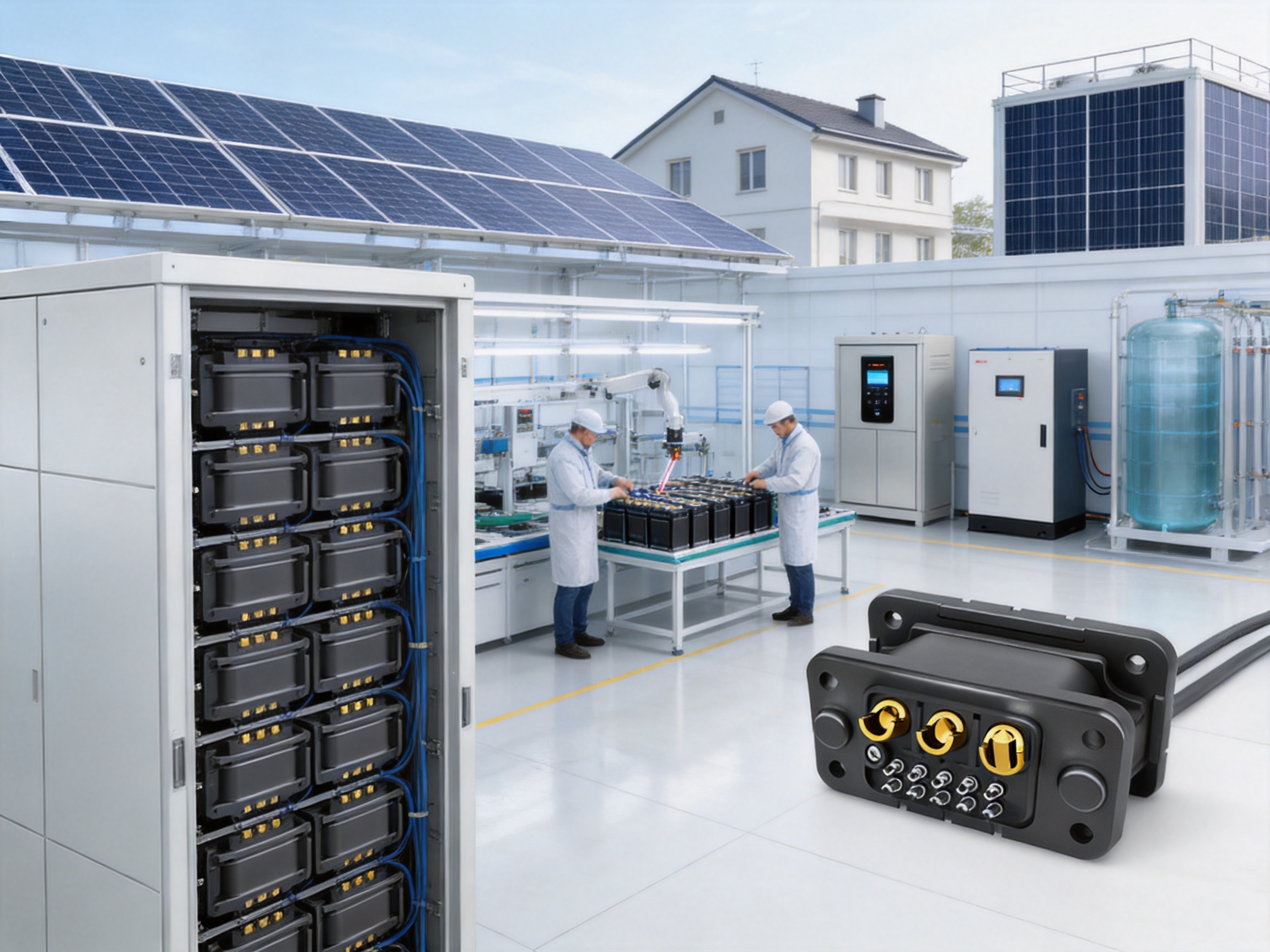
The rapid expansion of renewable energy is transforming the way electricity is generated, stored, and consumed. Solar photovoltaic systems, backup power units, commercial energy storage cabinets, industrial battery banks, and residential energy storage systems all require dependable electrical connections. As battery capacity increases, system designers are placing greater emphasis on modular construction, compact installation, safe blind mating, low electrical resistance, and simplified maintenance.
A stackable energy storage connector is designed to address these requirements directly. Unlike conventional battery interconnection methods that may depend on numerous exposed cables, manually aligned terminals, or complicated external wiring, a stackable connector supports a cleaner and more integrated arrangement between adjacent energy storage modules. Its floating blind-insertion structure allows the male and female ends to engage through guide columns, reducing the need for precise visual alignment during installation.
The product discussed in this article is a floating-type stackable energy storage connector designed for household energy storage, energy storage cabinets, industrial and commercial storage systems, photovoltaic equipment, inverters, water-cooling systems, and related new-energy applications. It uses PA66 insulation and gold-plated brass conductive components, supports current ratings from 50A to 70A in one configuration and from 120A to 240A in another configuration, and is engineered for demanding operating conditions ranging from -40°C to 125°C.
Beyond its electrical function, the connector is part of a broader trend toward integrated energy storage design. Modern storage systems are expected to be compact, attractive, serviceable, and safe. They must also support efficient manufacturing and repeatable assembly. By combining mechanical guidance, a retractable terminal structure, impact resistance, and a floating mounting approach, the stackable connector helps equipment manufacturers reduce wiring complexity while improving the overall organization of the battery system.
The Growing Need for Better Energy Storage Interconnections
Energy storage products are becoming more modular. A residential system may begin with a single battery module and later expand through additional stacked units. A commercial storage cabinet may contain multiple battery packs arranged vertically or horizontally. Industrial systems may require hundreds of electrical connections distributed across battery racks, power conversion equipment, protection devices, and monitoring components.
In traditional arrangements, each battery module may be connected through separate cables. While cables are flexible and widely available, a high number of external conductors can create several disadvantages. The installation may require more space, more fasteners, additional cable management, and longer assembly time. Each extra cable and terminal also represents another potential point of loosening, misrouting, abrasion, or incorrect polarity.
External cables can also affect the visual and mechanical quality of a finished energy storage product. A cabinet with loosely arranged cables can be difficult to inspect and service. Cables may obstruct ventilation paths, interfere with covers, or become exposed to mechanical stress. In household products, where appearance and space efficiency are important, excessive external wiring may be especially undesirable.
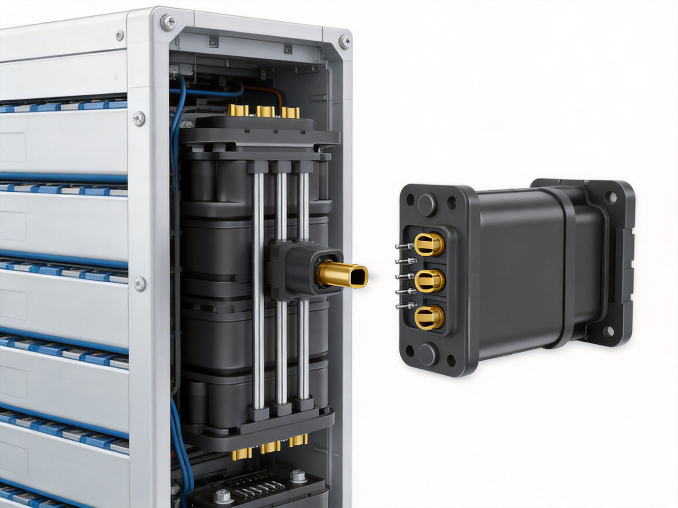
Stackable connectors provide an alternative approach. Instead of routing every connection externally, a connector can be positioned directly at the interface between modules. When the modules are stacked, the connector halves approach one another in a controlled direction. Guide columns assist the insertion process, while a floating structure allows limited positional compensation. The result is a more integrated connection that can reduce wiring clutter and simplify the assembly of modular battery systems.
This approach is particularly relevant to residential energy storage. Homeowners and installers generally expect equipment to occupy limited floor or wall space. They also expect the system to have a professional appearance and require minimal maintenance. A connector that supports direct stacking can contribute to a cleaner product architecture while allowing manufacturers to design expandable systems with repeatable module interfaces.
Product Overview
The stackable energy storage connector is a high-current DC connector intended for modular battery and energy storage equipment. It uses a floating installation structure and incorporates male and female mating ends. During assembly, the guide columns help the two sides find the correct position, enabling blind insertion without requiring the operator to maintain direct visual contact with the terminals.
The floating structure is one of the product’s defining characteristics. In a rigidly fixed connector arrangement, even a small dimensional deviation between stacked battery modules can make insertion difficult. Manufacturing tolerances, enclosure deformation, installation variation, or thermal expansion may result in an offset. A floating connector can accommodate a degree of positional variation, helping the mating components engage more smoothly.
The terminal can also be retracted. This feature is useful in a modular system because the terminal is less exposed when the connector is not fully mated. Retraction can help reduce the risk of accidental contact, impact, or damage during transport and installation. It also supports a more controlled mating sequence between battery modules.
The conductive component is made from brass with gold plating. Brass provides a practical combination of electrical conductivity, mechanical strength, formability, and compatibility with high-current terminal construction. Gold plating helps improve surface stability and resistance to oxidation and corrosion. The insulating body is made from PA66, an engineering polymer commonly selected for electrical components because of its mechanical strength, dimensional stability, and temperature performance.
The connector is rated for 220V DC in the stated product specification. Depending on the configuration, the rated current range may be 50A–70A or 120A–240A. Because battery voltage, current, duty cycle, cable size, thermal conditions, and installation method all affect connector performance, the final rating should be confirmed against the selected model and the complete system design.
Key Product Specifications
| Specification | Product Value | Design Significance |
| Insulating material | PA66 | Provides electrical insulation, mechanical strength, and elevated-temperature capability |
| Conductor material | Brass with gold plating | Supports reliable current transfer and improved surface durability |
| Rated voltage | 220V DC | Suitable for specified battery and energy storage DC applications |
| Rated current | 50A–70A or 120A–240A, depending on configuration | Allows selection for different energy storage architectures |
| Contact resistance | ≤0.5mΩ | Helps minimize voltage drop and resistive heat generation |
| Insulation resistance | >10MΩ at 500V DC | Supports electrical isolation between conductive and insulated sections |
| Dielectric strength | 500V AC or up to 4000V AC according to configuration | Verification value should be confirmed for the selected model |
| Mounting screw | M4 | Provides a standardized mechanical fastening approach |
| Mounting style | Floating | Allows compensation for limited positional misalignment |
| Flammability rating | UL94 V-0 | Supports flame-retardant enclosure and insulation requirements |
| Operating temperature | -40°C to 125°C | Supports cold-start and elevated-temperature operating environments |
The specifications above describe the principal design parameters supplied for the product. The dielectric strength is listed in the available technical information as 500V AC in one section and 500V AC/4000V AC in the specification table. This difference may reflect different product versions, test conditions, or optional configurations. Equipment manufacturers should request the applicable model datasheet and verify the required withstand voltage before final approval.
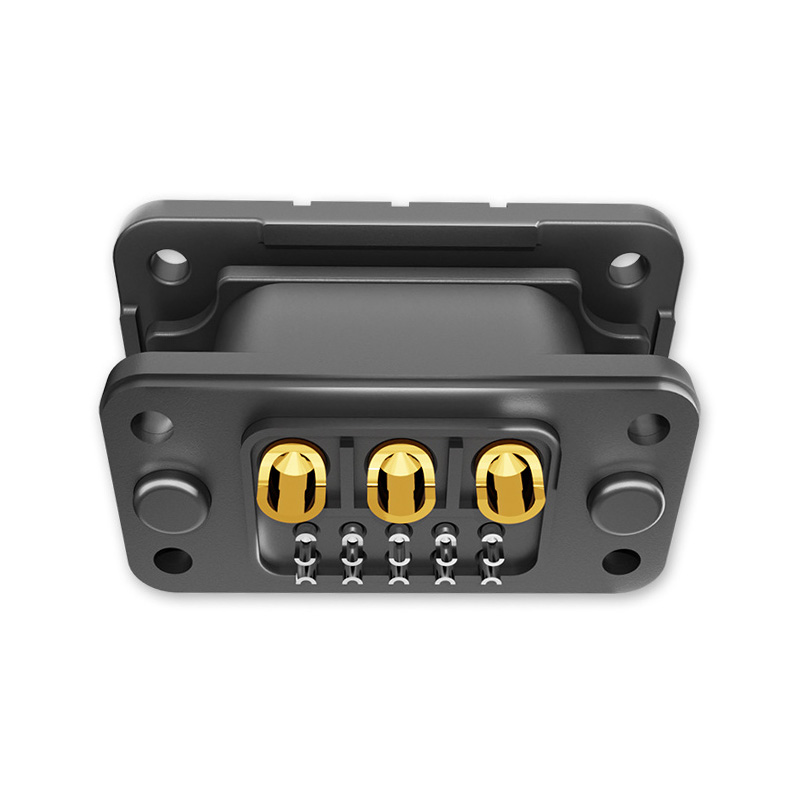
Stackable Energy Storage Connector
Floating Blind Insertion for Faster Assembly
Blind insertion is a major advantage in systems where the connector is located between stacked battery modules or inside a cabinet with limited visibility. During installation, the operator may not be able to see both connector halves at the same time. A conventional connector may require repeated adjustment, manual inspection, or access openings to confirm alignment. The floating stackable connector uses guide columns to help direct the male and female ends into the correct mating position.
This guided approach can reduce dependence on visual inspection. The installer positions the battery module according to the mechanical design, and the guide structure helps the connector complete the mating process. Such a design is valuable in high-volume production because it can make the assembly procedure more repeatable. It may also reduce the need for specialized training and lower the possibility of connector damage caused by forced or angled insertion.
The floating movement is not intended to replace correct mechanical design. The modules must still be positioned within the connector’s specified alignment range, and the mounting structure should prevent excessive lateral or angular loads. However, the ability to compensate for limited variation provides a valuable tolerance advantage compared with a fully rigid connector arrangement.
For manufacturers, easier blind insertion can influence more than assembly speed. It can improve process consistency, reduce rework, and support the development of modular products that are easier to install in the field. For installers, it can simplify the connection of equipment in confined spaces. For end users, better assembly control may contribute to improved long-term reliability.
Terminal Retraction and Contact Protection
The retractable terminal structure adds a further layer of practical protection. A terminal that remains fully exposed during transportation or module handling may be vulnerable to impact, contamination, or accidental contact with conductive objects. Retraction helps keep the contact element in a more protected position until the mating operation takes place.
In an energy storage system, a connector may be handled several times before the equipment reaches its final installation location. Battery modules can be moved through manufacturing stations, packaging areas, warehouses, and installation sites. During these stages, the connector may encounter vibration, drops, tools, packaging materials, or unintended contact. A retractable terminal can help reduce the risk associated with these handling conditions.
Terminal protection is also important for service operations. Modular battery products may be removed and reinstalled during inspection, replacement, or capacity expansion. A connector that provides better protection while unmated can support safer maintenance procedures, although all service work must still follow the battery system manufacturer’s isolation and safety requirements.
Low Contact Resistance and Electrical Efficiency
Contact resistance is a critical parameter in a high-current connector. The specified contact resistance of no more than 0.5 milliohms is intended to support efficient electrical transfer. Even a small resistance can produce heat when current is high, because power loss increases with the square of current. The relationship can be expressed as P = I²R, where P is heat generation, I is current, and R is resistance.
For example, at 100A, a 0.5 milliohm contact resistance corresponds to approximately 5 watts of power dissipation at the contact interface under the stated resistance condition. At higher currents, the thermal impact becomes more significant. This is why contact geometry, plating quality, terminal pressure, material selection, assembly accuracy, and heat dissipation must all be considered together.
Gold-plated brass supports a stable contact interface. The brass base provides mechanical resilience and current-carrying capability, while the gold surface helps protect the contact area from oxidation and environmental deterioration. Proper plating thickness and process control are important because the actual performance of a plated terminal depends on the quality and uniformity of the plating system.
Low contact resistance can also help reduce voltage drop between battery modules and power conversion equipment. Lower voltage drop may support more predictable system performance, especially when the battery is delivering high current to an inverter or other load. It can also reduce localized heating and help simplify thermal design, provided the connector is operated within its specified rating.
Materials Selected for Energy Storage Applications
PA66 Insulation
PA66 is widely used in electrical and mechanical components where a balance of strength, durability, insulation, and temperature resistance is required. In this connector, the PA66 housing separates the conductive elements from the surrounding structure and helps maintain the intended creepage and clearance distances.
The material’s mechanical strength is important because the housing must support the terminal during insertion, mating, unmating, vibration, and repeated handling. Dimensional stability also matters. If the housing changes shape significantly with temperature or mechanical load, alignment and contact pressure may be affected. Material selection must therefore be combined with suitable mold design, processing control, and quality inspection.
Gold-Plated Brass Conductors
Brass is a practical conductor material for connector terminals because it offers good machinability, strength, spring characteristics, and electrical performance. A connector terminal must do more than carry current. It must also maintain mechanical contact force, withstand insertion cycles, and resist deformation during assembly.
Gold plating can provide a stable contact surface and improve resistance to oxidation. This is particularly useful in products that may be stored for extended periods or operate in environments where humidity and contamination are concerns. The plating process must be controlled carefully to ensure adequate coverage and adhesion. Terminal cleaning, dimensional inspection, and electrical testing are also important parts of a reliable manufacturing process.
Impact Resistance and Mechanical Reliability
Energy storage connectors are exposed to mechanical forces throughout their service life. Battery modules may be inserted into cabinets, stacked during assembly, transported over roads, or subjected to vibration from cooling equipment and power electronics. The connector must therefore be designed to tolerate reasonable impact and handling forces without losing alignment or electrical performance.
The product’s impact-resistant design supports this requirement. Its guide columns help direct the mating motion, reducing the likelihood that the terminals will be forced together at an incorrect angle. The housing protects the conductive parts and helps distribute mechanical stress. The floating structure can also reduce concentrated loading caused by small installation offsets.
Mechanical reliability depends on the entire interface, not only the connector body. The battery enclosure, mounting panel, M4 screws, module frame, and support structure must be designed to work together. Fasteners should be tightened according to the applicable assembly procedure. Excessive tightening may deform the housing or restrict the floating movement, while insufficient tightening may allow unwanted movement or vibration.
For this reason, a professional connector supplier should provide dimensional drawings, allowable alignment tolerances, recommended fastening conditions, mating-cycle information, and installation instructions. These documents allow the connector to be integrated correctly into the battery module and help prevent performance problems caused by improper mounting.
Advantages Compared with Conventional External Cable Connections
Reduced Wiring Complexity
One of the most visible advantages is the potential reduction in external cables. A stackable connector can place the electrical interface directly at the module boundary, allowing adjacent units to connect through a defined structural position. This may eliminate some cable routing, cable clamps, bend-radius requirements, and additional terminal hardware.
Fewer external cables can simplify the internal arrangement of a storage cabinet. The design team may gain more freedom to position busbars, fuses, contactors, battery management components, cooling channels, and service panels. A more organized interior can also make inspection easier.
Improved Product Appearance
Residential and commercial energy storage products are increasingly installed in visible locations. A clean appearance supports customer confidence and reflects the quality of the equipment. Direct stackable connections can reduce hanging cables and exposed wiring, producing a more integrated visual design.
Faster and More Repeatable Installation
Cable-based connections often require separate steps for routing, cutting, crimping, fastening, and inspection. A purpose-designed connector can consolidate the interface into a mating operation supported by guide columns. This can improve assembly efficiency and reduce variation between products.
Better Serviceability
Modular equipment is easier to service when the interconnection points are standardized and easy to access. A stackable connector can support the removal and replacement of individual battery modules without requiring technicians to manage numerous loose cables. The actual maintenance procedure depends on the equipment design and safety controls, but a simplified interface can make the mechanical process more orderly.
More Effective Use of Space
External cables require bend radius, routing space, and clearance from moving or hot components. A direct stackable interface can help manufacturers design more compact systems. This is particularly useful in household energy storage, where installation space may be limited, and in cabinet systems where every millimeter affects capacity and thermal layout.
Applications Across the Energy Storage Industry
Household Energy Storage
Residential battery systems frequently use a modular architecture. Customers may purchase a basic capacity and later add modules as their energy needs change. A stackable connector supports this expansion model by providing a repeatable electrical and mechanical interface between battery units.
For home applications, appearance, installation simplicity, and safety are especially important. A system with fewer visible cables can be easier to install in a utility room, garage, or indoor equipment area. The compact connection approach may also help manufacturers produce thinner or more visually integrated battery cabinets.
Energy Storage Cabinets
Energy storage cabinets may contain several battery modules, power distribution components, and monitoring devices. A stackable connector can help organize the connection between modules and reduce the amount of loose wiring within the enclosure. It can also support standardized cabinet platforms in which the number of modules varies according to required capacity.
Commercial Energy Storage
Commercial systems must often balance capacity, installation cost, service requirements, and site limitations. The connector can support modular system construction and may simplify the work required to add or replace battery units. The product is suitable for consideration in applications involving commercial power management, peak-load support, backup power, and renewable energy integration.
Industrial Energy Storage
Industrial installations typically place higher demands on mechanical durability, current capacity, thermal management, and maintenance planning. The available current configurations, including higher-current versions, allow system designers to evaluate the connector for different power architectures. Final suitability must be determined through electrical, thermal, mechanical, and environmental verification.
Photovoltaic and Inverter Systems
Solar photovoltaic systems increasingly use battery storage to improve self-consumption, provide backup power, and reduce dependence on the grid during peak periods. The connector can be used in the battery-side architecture of systems that interface with inverters. Its DC rating and insulation characteristics make it relevant to the connection between battery modules and associated energy conversion equipment.
Water-Cooled and Thermally Managed Systems
Some modern battery systems use liquid or water-cooling technology to control cell temperature. In such products, the electrical connector must coexist with cooling channels, pipes, manifolds, and thermal components. A compact and guided connection can help preserve space for thermal management. Designers should nevertheless verify sealing, condensation, creepage, clearance, and temperature conditions for the complete assembly.
Advanced Manufacturing and Engineering Strengths
Zhejiang Zhongyan New Energy Co., Ltd. specializes in new-energy conductive components and precision electrical connection solutions. Its product scope includes high-voltage electrical copper foil soft connections, special-shaped soft connections, battery soft connections, and other components used in energy storage, electric vehicles, rail transit, communications, power distribution, and related industries.
The company’s experience in soft connection technology is relevant to the development of advanced energy storage connectors. Soft connections and modular connectors both require careful control of conductivity, mechanical flexibility or alignment, dimensional accuracy, contact reliability, and thermal behavior. This background supports a product-development approach that considers the full electrical and mechanical system rather than treating the connector as an isolated part.
The company has established capabilities covering product design, research and development, manufacturing, testing, and solution support. Its technical team includes experienced engineers, while its production organization uses professional equipment and quality management processes intended to provide stable and consistent product performance.
Polymer Diffusion Welding Technology
The company has independently developed polymer diffusion welding technology for new-energy precision components. Polymer-based connection and insulation structures require control of material compatibility, bonding conditions, temperature, pressure, surface preparation, and dimensional stability. Properly developed processes can support reliable integration between conductive components and insulating or protective materials.
In energy storage systems, process stability is essential because small changes in connection quality can affect resistance, heat generation, mechanical strength, and long-term reliability. A manufacturing system that combines material knowledge with controlled process parameters can help reduce variation between production batches.
Laser Technology
Laser technology can be applied to precision joining, localized processing, marking, welding, and inspection. Its advantages may include concentrated energy input, fine process control, reduced heat-affected areas, and compatibility with automated production. For conductive components, laser processing can support consistent joints and accurate manufacturing of complex geometries.
The value of laser technology depends on the specific application and process qualification. Parameters such as power, pulse duration, travel speed, focus position, shielding, and material condition must be optimized. When these factors are controlled through a documented production process, laser equipment can contribute to repeatable manufacturing of high-reliability electrical components.
Integrated Research and Development
The company is developing an innovation system covering materials science, precision machining, testing, and verification. This multidisciplinary structure is important for energy storage products because electrical performance is closely connected with mechanical design and material behavior.
A connector may meet its initial electrical target but still fail if the housing cracks, the terminal loses spring force, the plating deteriorates, or the mounting structure causes excessive stress. Integrated research helps identify these relationships earlier in the development process. It also supports customization for customers with different module dimensions, current requirements, installation directions, or environmental conditions.
Quality Control and Product Verification
Reliable energy storage connectors require more than a single resistance measurement. A complete verification program should examine electrical, mechanical, thermal, environmental, and material-related performance. Typical evaluations may include contact resistance, insulation resistance, dielectric withstand, current-carrying temperature rise, insertion and withdrawal force, mating durability, vibration, impact, temperature cycling, humidity exposure, and material flammability.
The stated product information includes a contact resistance of no more than 0.5mΩ, insulation resistance greater than 10MΩ at 500V DC, dielectric strength values according to configuration, UL94 V-0 flammability, and an operating temperature range of -40°C to 125°C. These specifications provide a foundation for evaluation, but the connector should be tested in the actual battery assembly as well.
System-level validation is necessary because connector performance can be affected by cable size, busbar design, enclosure ventilation, ambient temperature, neighboring components, fastening torque, and current duty cycle. A connector that performs well in a laboratory fixture may experience a different thermal environment inside a compact battery cabinet.
Manufacturers should also consider production traceability. Lot identification, raw material records, plating inspection, dimensional inspection, electrical test results, and process records can support quality assurance and after-sales analysis. For large energy storage projects, traceability helps equipment manufacturers maintain consistent supply and investigate any field issue efficiently.
Design Considerations for Equipment Manufacturers
The connector should be selected at the beginning of the battery module design process rather than added after the enclosure has been completed. Its mounting location affects module spacing, guide-column clearance, terminal access, busbar or cable routing, and the mechanical support structure.
Designers should confirm the following points before production release:
First, the operating voltage and continuous or peak current must be compared with the connector’s rated values. The highest expected current, overload duration, ambient temperature, and duty cycle should be included in the evaluation.
Second, the connector’s allowable floating range and alignment tolerance must match the dimensional tolerance of the stacked modules. The guide columns should not be used to correct excessive misalignment or to force modules into position.
Third, the mounting screws and supporting structure must be strong enough to withstand installation and operating loads. The floating function should remain available after fastening. Installation instructions should specify the correct screw type, tightening procedure, and any required washers or locking elements.
Fourth, creepage and clearance distances must be evaluated in the final enclosure. Dust, moisture, condensation, and conductive contamination can affect insulation performance. The connector’s insulation rating should be considered together with the battery enclosure and the applicable product safety requirements.
Fifth, thermal performance should be evaluated at the intended current. The connector should not be placed near components that introduce unnecessary heat, and the enclosure should allow appropriate heat dissipation. If the product is used in a water-cooled system, the design should address condensation and fluid leakage risks.
Finally, service procedures should be defined clearly. Operators should know how to isolate the battery, verify the absence of hazardous voltage, disconnect the modules, and protect unmated connectors during maintenance. The connector simplifies physical interconnection, but it does not remove the need for electrical safety procedures.
Customization and OEM Support
Different energy storage platforms may require different connector dimensions, terminal configurations, mounting directions, current levels, and mating arrangements. A professional supplier should be able to evaluate drawings, interface requirements, electrical targets, and installation constraints before recommending a product version.
Customization may include housing geometry, guide-column dimensions, terminal configuration, mounting-hole location, conductor size, plating specification, cable or busbar interface, and labeling. The extent of customization depends on production volume, technical feasibility, tooling requirements, and verification needs.
OEM cooperation is most effective when technical communication begins early. The customer should provide information about rated voltage, continuous and peak current, module dimensions, stacking direction, expected mating cycles, operating temperature, vibration exposure, enclosure conditions, and required certifications. The supplier can then propose a suitable design and prepare samples for mechanical and electrical validation.
Prototype testing should include both individual connector tests and complete module tests. The connector must be checked after installation, fastening, thermal cycling, vibration, and repeated mating. This process confirms that the selected design performs as expected within the actual battery system rather than only under isolated laboratory conditions.
Why the Product Is Well Suited to Modern Modular Battery Systems
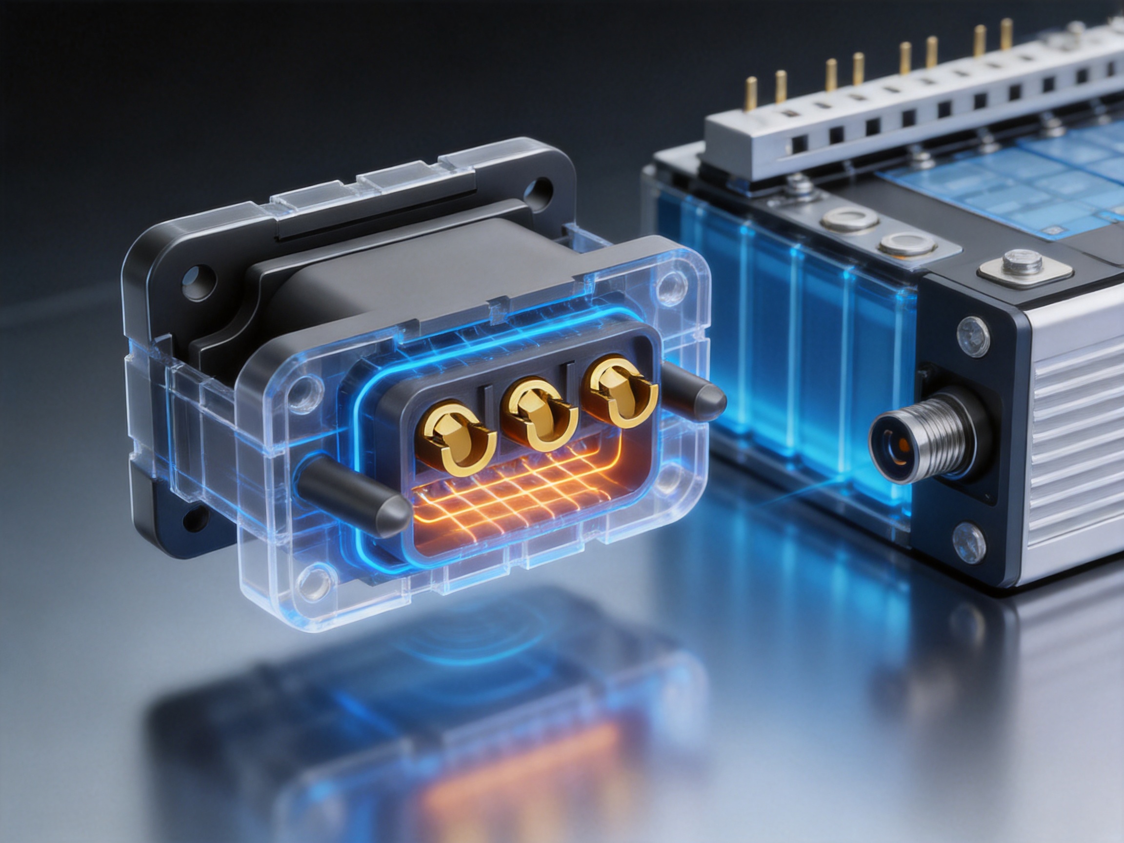
The principal strength of the stackable energy storage connector is the way it combines several useful features into one interface. Floating installation addresses limited alignment variation. Blind insertion supports assembly where direct visual inspection is difficult. Guide columns help control the mating path. Terminal retraction provides protection during handling. Gold-plated brass supports a stable conductive interface. PA66 insulation provides a robust housing material. The low contact resistance target supports efficient current transfer, while the broad operating temperature range supports diverse installation environments.
Competitors based primarily on loose external cables may still be appropriate for certain installations, particularly where modules are widely separated or where flexible routing is essential. However, cable-based systems may require more assembly operations and greater attention to routing, protection, and service access. A purpose-built stackable connector offers a more integrated alternative for equipment platforms designed around adjacent modular units.
The product is also well matched to the direction of energy storage product development. Battery systems are becoming more standardized, scalable, and service-oriented. Manufacturers need connection methods that support capacity expansion without redesigning the entire system. A standardized stackable interface can help create families of products with common module dimensions and repeatable assembly procedures.
At the same time, the supplier’s expertise in conductive components, soft connections, material engineering, laser technology, and precision manufacturing provides a foundation for continued product development. This combination of product function and manufacturing capability is important for customers seeking more than a catalog component. It enables technical cooperation, customized design, and process support for applications with demanding electrical and mechanical requirements.
Installation and Handling Recommendations
Before installation, inspect the connector housing, terminal surfaces, guide columns, mounting holes, and protective features. Do not use a connector if the housing is cracked, the terminal is deformed, or the contact surface is contaminated. Confirm that the selected connector rating matches the battery module design.
Align the modules according to the equipment manufacturer’s mechanical instructions. Allow the guide columns to control the insertion path, and do not apply excessive side force. If unusual resistance is felt during mating, stop the operation and check for misalignment, foreign objects, damaged parts, or interference from the enclosure.
Use the specified M4 mounting hardware and follow the recommended tightening procedure. Do not restrict the floating movement by clamping the connector body in a way that prevents its intended compensation. After assembly, verify that the connector is fully seated and that the module is mechanically supported independently of the electrical interface.
For unmated connectors, use the designated protective measures. Keep the contact area free from metal tools, loose fasteners, dust, moisture, and other contaminants. During transportation, protect the connector from direct impact and prevent the terminal from being loaded by packaging materials.
All high-voltage battery work must be performed by qualified personnel according to the equipment manufacturer’s safety procedures. The connector’s design features improve physical connection and protection, but they do not substitute for isolation, lockout, voltage verification, personal protective equipment, or other required controls.
Frequently Asked Questions
What is a stackable energy storage connector?
A stackable energy storage connector is a high-current electrical interface designed to connect adjacent battery modules or energy storage units. It is commonly integrated into a stacking structure so that modules can connect directly without relying on numerous external cables.
What does floating mounting mean?
Floating mounting means that the connector has a controlled ability to compensate for limited positional variation. This helps the male and female ends align during module stacking, provided that the installation remains within the specified tolerance range.
What is blind insertion?
Blind insertion is a mating method in which the operator does not need to visually inspect the terminals throughout the connection process. Guide columns help direct the male and female connector ends into the correct position.
What current ratings are available?
The supplied specifications identify a 50A–70A range and a 120A–240A range, depending on the product configuration. The correct rating must be selected according to the specific model, battery voltage, current duty cycle, ambient temperature, and installation conditions.
What is the rated voltage?
The stated rated voltage is 220V DC. The final application must be reviewed against the product datasheet, the battery system voltage, transient conditions, insulation requirements, and relevant safety standards.
Why is gold plating used on the brass terminal?
Gold plating helps provide a stable contact surface and improves resistance to oxidation and corrosion. Brass provides the underlying mechanical and electrical structure, while the plated surface supports reliable contact performance.
What is the purpose of the retractable terminal?
The retractable terminal helps protect the contact element when the connector is not fully mated. It can reduce exposure to accidental contact, impact, and handling damage during transportation, assembly, and service.
Is the connector suitable for residential battery systems?
Yes. It is designed for consideration in household energy storage systems, especially modular products in which battery units are stacked to increase capacity. The final suitability depends on voltage, current, mechanical design, environmental conditions, and required certifications.
Can it be used in commercial or industrial storage cabinets?
Yes. The product is also intended for energy storage cabinets, commercial energy storage, industrial energy storage, photovoltaic systems, inverters, and related applications. System designers should verify the appropriate current version and perform complete system-level validation.
What insulation material is used?
The insulating body uses PA66. This engineering polymer is selected for its combination of insulation, strength, dimensional stability, and temperature capability.
What is the operating temperature range?
The stated operating temperature range is -40°C to 125°C. Actual performance also depends on current load, heat dissipation, enclosure temperature, mating condition, and environmental exposure.
What does the UL94 V-0 rating indicate?
UL94 V-0 is a flammability classification for polymer materials. It indicates a defined level of resistance to flame propagation under the applicable test method. The rating of the connector material does not by itself certify the complete battery system.
How can the connector reduce installation complexity?
By locating the electrical interface at the module boundary, the connector can reduce the number of external cables, routing operations, cable clamps, and separate terminal fasteners. Its guide columns and floating structure can also make module mating more repeatable.
Does the connector eliminate the need for safety procedures?
No. Energy storage systems can contain hazardous voltage and high fault current. Isolation, lockout, voltage verification, protective equipment, and qualified service personnel remain essential for every installation and maintenance operation.
Can the product be customized?
Customized solutions may be possible depending on the application. Customers should provide electrical ratings, mechanical drawings, module dimensions, stacking direction, environmental conditions, and service requirements for technical evaluation.
Conclusion
The stackable energy storage connector provides a practical connection solution for the next generation of modular battery systems. Its floating blind-insertion structure addresses alignment and installation challenges, while guide columns help support repeatable mating without continuous visual inspection. The retractable terminal improves protection during handling, and the impact-resistant construction supports demanding assembly and service environments.
With PA66 insulation, gold-plated brass conductors, a specified contact resistance of no more than 0.5mΩ, 220V DC rated voltage, UL94 V-0 material performance, and an operating range of -40°C to 125°C, the connector is designed for a broad range of household, commercial, industrial, photovoltaic, inverter, and energy storage applications.
Its advantages become especially clear when compared with highly cable-dependent connection methods. By reducing wiring complexity, improving appearance, supporting compact layouts, and simplifying modular assembly, the connector can help equipment manufacturers create more integrated and serviceable storage products.
The manufacturing strength behind the product is equally important. Expertise in new-energy conductive components, soft connections, precision machining, polymer diffusion welding, laser technology, testing, and customized engineering supports the development of stable and application-specific solutions. For customers seeking a reliable connection platform for expandable battery systems, the stackable energy storage connector represents a strong option for improving efficiency, organization, and long-term product value.
References
1. IEC 60664-1, Insulation Coordination for Equipment Within Low-Voltage Systems.
2. IEC 61984, Connectors: Safety Requirements and Tests.
3. IEC 62133, Safety Requirements for Portable Sealed Secondary Cells and Batteries.
4. UL 94, Tests for Flammability of Plastic Materials for Parts in Devices and Appliances.
5. National Fire Protection Association, NFPA 855, Standard for the Installation of Stationary Energy Storage Systems.
6. International Electrotechnical Commission, Technical Guidance for Electrical Energy Storage Systems.
7. Product technical information supplied for the stackable energy storage connector, including material, electrical, mechanical, and environmental specifications.
8. Technical information supplied by Zhejiang Zhongyan New Energy Co., Ltd. concerning new-energy conductive components, soft connections, precision manufacturing, polymer diffusion welding, laser technology, and customized electrical connection solutions.
Product: Stackable Energy Storage Connector

Driven by the development of new energy and aiming for "zero carbon".
Copyright © Zhejiang Zhongyan New Energy Co., Ltd. All Rights Reserved.
