 English
 Español

High-Current Copper Bar Connectors for Energy Storage and High-Voltage Battery Systems
Reliable electrical connections are essential to the safety, efficiency, and service life of modern energy storage equipment. As battery systems become larger, more compact, and more powerful, connection components must carry higher currents while maintaining low electrical losses, strong insulation, mechanical stability, and dependable environmental protection. The Copper Bar Connector is designed to address these requirements in energy storage systems, high-voltage battery packs, electric vehicles, solar power installations, industrial power equipment, and related electrical applications.
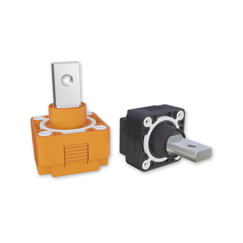
This single-core, wall-mount terminal combines a nickel-plated T2Y pure copper conductor with a robust PA66 insulation shell. Its construction is intended to support stable current transmission, secure busbar and cable attachment, and reliable operation in demanding environments. Depending on the selected configuration, the connector supports rated current options from 200 A to 600 A, a rated voltage of up to 1500 V DC, and compatible busbars and cables in several sizes.
Beyond its electrical performance, the connector is engineered for practical installation. Standardized mounting hardware, a compact terminal structure, IP67 protection, high insulation resistance, and UL94 V-0 flame retardancy help simplify system integration while improving operational safety. These features make it suitable for professional energy storage assemblies where low contact resistance, thermal control, mechanical reliability, and serviceability are all important.
Product Overview
The Copper Bar Connector is a high-current connection component for linking copper busbars, power cables, battery modules, and distribution structures. It is configured as a single-core terminal and is suitable for wall-mounted installation in battery cabinets, energy storage converters, power distribution units, and other electrical enclosures.
The main conductive element is made from T2Y pure copper and finished with nickel plating. Copper provides high electrical conductivity and helps reduce voltage drop during current transmission. Nickel plating improves surface durability and contributes to corrosion resistance, particularly in environments where humidity, temperature variation, or industrial contaminants may affect exposed conductive surfaces.
The insulating body is manufactured from PA66. This engineering polymer provides mechanical strength, dimensional stability, electrical insulation, and good resistance to temperature variation. The housing is designed to separate the conductive path from the surrounding enclosure and installation structure, reducing the risk of accidental contact, insulation breakdown, and electrical tracking.
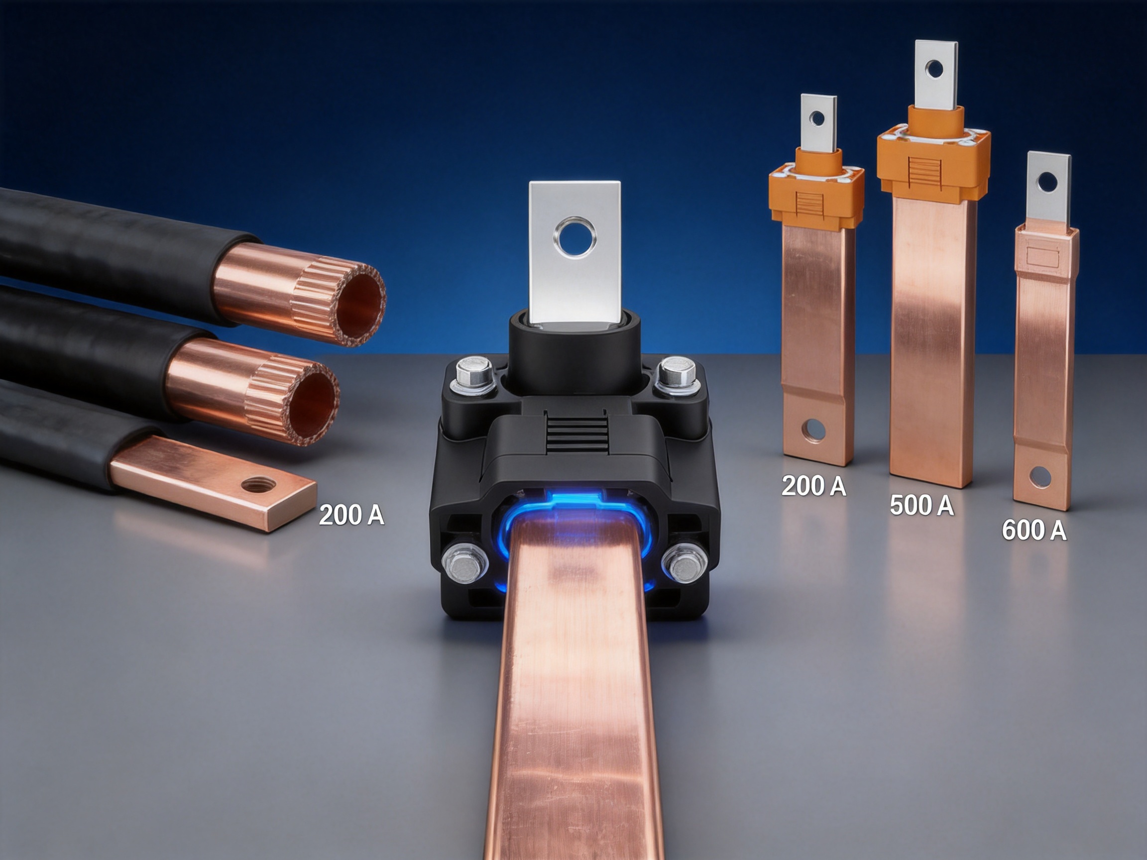
The connector is available for different current and conductor-size requirements. The supplied technical information identifies configurations for 200 A and 250 A with a 20 × 4 mm busbar and 50 mm² or 70 mm² cables. Higher-current configurations include 300 A and 350 A options for 25 × 6 mm busbars and 95 mm² or 120 mm² cables, as well as 400 A, 450 A, and 600 A options for 30 × 10 mm busbars and 150 mm² or 185 mm² cables.
Because electrical systems differ in operating conditions and design margins, the exact connector configuration should be selected according to continuous current, peak current, ambient temperature, cable installation method, enclosure ventilation, busbar dimensions, required creepage and clearance distances, and applicable safety standards.
Why High-Current Connection Quality Matters
In an energy storage system, the connector is not simply a mechanical joining point. It forms part of the electrical, thermal, and safety architecture of the complete assembly. A poor connection can create increased resistance, localized heating, energy losses, voltage instability, and accelerated degradation of surrounding materials.
Even a small increase in contact resistance can become significant when large currents flow continuously. The heat generated at a connection is related to the square of current and the resistance of the connection. This means that a connection carrying several hundred amperes requires carefully controlled contact surfaces, appropriate tightening torque, adequate conductor cross-section, and effective heat dissipation.
Loose hardware, insufficient contact area, surface oxidation, poor alignment, or inappropriate conductor sizing can all increase electrical resistance. Over time, thermal cycling may further loosen mechanical connections or change the dimensions of adjacent materials. A high-quality connector must therefore offer consistent electrical contact and maintain mechanical stability throughout repeated charging and discharging cycles.
The Copper Bar Connector is designed around these requirements. Its nickel-plated copper conductor helps provide a stable conductive surface, while the specified mounting screws and tightening torques support controlled installation. The insulated structure helps protect the connection from accidental contact and environmental contamination, and the IP67 construction is intended to resist dust and temporary immersion when correctly installed.
Key Electrical Advantages
High Conductivity Copper Conductor
The use of T2Y pure copper provides a strong foundation for high-current power transmission. Copper is widely used in power distribution because it combines high conductivity with good mechanical workability. A conductive path made from suitable copper can reduce resistive losses, limit voltage drop, and help manage the heat produced during operation.
For battery and energy storage applications, these characteristics are especially important. Power may flow in both directions during charging and discharging, and current levels can remain high for extended periods. A conductive component with low resistance helps improve overall system efficiency and reduces the amount of energy converted into unwanted heat.
Nickel-Plated Contact Surface
The copper conductor is nickel plated to improve surface performance. Bare copper can be affected by oxidation and environmental exposure, which may change the contact interface over time. Nickel offers a durable surface layer with strong resistance to corrosion and wear. It also supports more stable contact performance when the connector is installed in humid, industrial, or outdoor environments.
The specified contact resistance is no greater than 0.5 mΩ under the stated test condition of 100 mA. Low contact resistance helps reduce localized heat generation at the joint and supports efficient current transmission. In practical applications, the final performance also depends on correct installation, clean contact surfaces, suitable tightening torque, conductor preparation, and compliance with the recommended current rating.
Support for High Current Levels
The product family covers several current ranges, allowing system designers to select a terminal matched to the required power level. The listed configurations include 200 A, 250 A, 300 A, 350 A, 400 A, 450 A, and 600 A ratings. This range supports applications from medium-sized battery cabinets to higher-power storage and distribution equipment.
Different current ratings are associated with different busbar and cable dimensions. This is important because conductor size must be matched to the expected current, heat dissipation, installation environment, and duty cycle. Selecting a larger connector does not automatically compensate for an undersized cable or busbar. The complete current path must be evaluated as a system.
Insulation and Safety Performance
PA66 Insulation Housing
The PA66 insulation shell provides electrical separation between the conductive core and the mounting environment. PA66 is commonly used in electrical and industrial components because it offers a useful balance of strength, rigidity, thermal performance, and processability.
A strong insulating housing helps protect installers and maintenance personnel from accidental contact with energized parts. It also supports consistent spacing inside a battery enclosure, reducing the possibility of short circuits caused by movement, vibration, loose hardware, or contact with adjacent conductive structures.
High Insulation Resistance
The specified insulation resistance is greater than 500 MΩ. High insulation resistance helps limit leakage currents between the conductive terminal and the surrounding structure. This is particularly important in high-voltage DC battery systems, where insulation monitoring and fault detection are important parts of the overall safety design.
Insulation resistance can be influenced by moisture, contamination, temperature, installation damage, and aging. The connector’s IP67 construction and robust housing help reduce exposure to external contaminants, but the complete assembly must still be kept clean and installed according to appropriate workmanship requirements.
Dielectric Strength
The connector is specified with a dielectric strength of 4000 V AC. This indicates the ability of the insulation system to withstand a high-voltage test without electrical breakdown under the defined test conditions. Dielectric strength is a key consideration in high-voltage battery packs, power conversion systems, and energy storage cabinets.
High-voltage testing should be performed only with suitable equipment and procedures. The test voltage, duration, ramp rate, test environment, and acceptance criteria should follow the applicable product and system standards. Testing personnel must also follow strict electrical safety procedures.
UL94 V-0 Flame Retardancy
The PA66 housing is specified as UL94 V-0 flame retardant. This classification indicates that the material is designed to limit flame propagation under the conditions of the relevant flammability test. Flame-retardant insulation is valuable in battery and power equipment because it can help reduce the spread of fire from an electrical fault or nearby heat source.
Flame retardancy does not make a complete battery system fireproof. Battery safety depends on cell chemistry, protection circuits, thermal management, enclosure design, ventilation, monitoring, spacing, and emergency controls. However, using a flame-retardant connector housing is an important part of responsible component selection.
Environmental Protection and Operating Conditions
IP67 Protection
The connector is rated IP67. The first digit indicates protection against dust ingress, while the second digit indicates protection against temporary immersion in water under defined test conditions. This rating makes the product suitable for applications where equipment may be exposed to dust, splashing water, condensation, or challenging outdoor conditions.
IP67 protection depends on the complete installed configuration. Cable entry, sealing surfaces, mounting interfaces, unused openings, and enclosure design must all be correctly managed. Improper installation, damaged seals, incorrect cable preparation, or mechanical deformation can reduce the actual protection level of the finished system.
Wide Temperature Range
The specified operating temperature range is -40°C to 125°C. This broad range supports installation in cold climates, outdoor energy storage stations, industrial environments, and equipment exposed to substantial temperature variation.
Temperature affects electrical resistance, insulation performance, mechanical expansion, and connector durability. Copper, nickel, PA66, cables, busbars, and enclosure materials may expand at different rates. A connector designed for a wide temperature range can help maintain reliable operation, but system designers should still consider thermal cycling, current derating, heat dissipation, and the maximum temperature of nearby cells and electronic components.
Suitability for Harsh Applications
Energy storage systems may be installed in utility substations, commercial buildings, remote solar facilities, factory power rooms, data centers, marine-adjacent environments, and outdoor cabinets. These locations can expose electrical components to vibration, dust, humidity, temperature changes, and maintenance activity.
The combination of nickel-plated copper, PA66 insulation, IP67 sealing, flame retardancy, and a wide temperature rating gives this connector a strong foundation for such environments. It is particularly appropriate where a standard unsealed terminal may not provide sufficient protection or where a low-current connector would create unnecessary thermal limitations.
Copper Bar Connector
Mechanical Design and Installation Features
Wall-Mount Terminal Structure
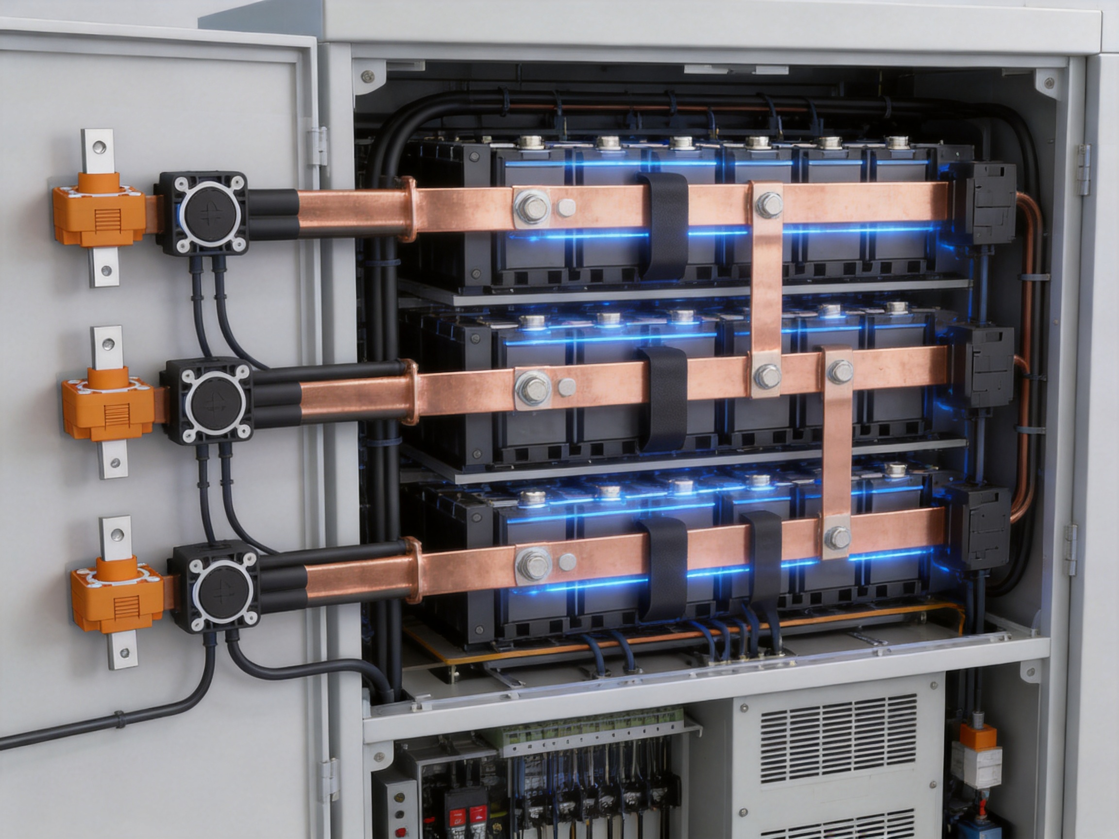
The wall-mount format allows the connector to be integrated into the side wall or internal partition of an electrical enclosure. This can help separate high-current conductors from control wiring and can improve the organization of the battery system. A defined mounting position may also simplify inspection and maintenance.
Wall-mounted installation is useful in battery cabinets where the busbar path must pass through a structural panel or connect between separate compartments. The final mounting surface should be sufficiently rigid and should not impose excessive force on the connector body. Mechanical alignment is important because side loading can affect the housing, fasteners, cable lug, and conductor interface.
Specified Mounting Hardware
The lower-current configurations use M8 and M4 mounting screws, with stated tightening torques of 12 N·m for M8 and 2 N·m for M4. Higher-current versions use M10 and M4 mounting screws, with a stated tightening torque of 30 N·m for M10 and 2 N·m for M4.
Controlled tightening torque is essential for achieving consistent contact pressure. Under-tightening may produce insufficient contact and vibration resistance, while over-tightening may damage threads, deform the housing, or place excessive stress on the conductor and insulation. Installation should use a calibrated torque tool whenever possible.
Thread engagement, washer selection, fastener material, surface flatness, and the use of locking features should be considered during system design. If the connector is installed in a high-vibration environment, additional mechanical retention may be appropriate, provided it does not interfere with insulation or sealing performance.
Busbar Compatibility
The connector supports several copper busbar dimensions. The listed options include 20 × 4 mm, 25 × 6 mm, and 30 × 10 mm busbars. This range allows the product family to serve different current levels and mechanical layouts.
Busbar preparation should include correct cutting, drilling, deburring, cleaning, and alignment. Sharp edges can damage insulation or create stress concentrations. Contaminated or oxidized surfaces may increase contact resistance. The busbar should be supported so that its weight and vibration do not transfer excessive mechanical force to the connector.
Cable Compatibility
Depending on the configuration, the connector is compatible with 50 mm², 70 mm², 95 mm², 120 mm², 150 mm², and 185 mm² cables. Cable selection should account for continuous current, peak current, ambient temperature, installation method, insulation rating, bending radius, and applicable electrical codes.
Large power cables can be heavy and difficult to route. A suitable cable support system should be installed close enough to the connector to prevent the terminal from carrying the cable’s mechanical load. Cable lugs must be correctly crimped, properly sized, and fully seated. Poor crimping can create a hidden high-resistance point even when the connector itself is properly designed.
Technical Specifications
The following table summarizes the main technical parameters provided for the Copper Bar Connector product family. Actual configuration, ratings, dimensions, and installation requirements should be confirmed before production use.
| Parameter | Configuration A | Configuration B | Configuration C |
| Insulation material | PA66 | PA66 | PA66 |
| Conductor material | T2Y pure copper with nickel plating | T2Y pure copper with nickel plating | T2Y pure copper with nickel plating |
| Number of cores | Single-core | Single-core | Single-core |
| Rated current | 200 A / 250 A | 300 A / 350 A | 400 A / 450 A / 600 A |
| Rated voltage | 1500 V DC | 1500 V DC | 1500 V DC |
| Contact resistance | ≤0.5 mΩ at 100 mA | ≤0.5 mΩ at 100 mA | ≤0.5 mΩ at 100 mA |
| Insulation resistance | >500 MΩ | >500 MΩ | >500 MΩ |
| Dielectric strength | 4000 V AC | 4000 V AC | 4000 V AC |
| Compatible busbar | 20 × 4 mm | 25 × 6 mm | 30 × 10 mm |
| Compatible cable sizes | 50 mm² / 70 mm² | 95 mm² / 120 mm² | 150 mm² / 185 mm² |
| Mounting screws | M8 at 12 N·m; M4 at 2 N·m | M10 at 30 N·m; M4 at 2 N·m | M10 at 30 N·m; M4 at 2 N·m |
| Protection rating | IP67 | IP67 | IP67 |
| Flammability rating | UL94 V-0 | UL94 V-0 | UL94 V-0 |
| Operating temperature | -40°C to 125°C | -40°C to 125°C | -40°C to 125°C |
Advantages Compared with Conventional Connection Methods
Compared with Bare Bolted Joints
A basic bare bolted joint may offer a simple and inexpensive connection, but it often provides limited insulation and environmental protection. Exposed metal surfaces can be more vulnerable to oxidation, accidental contact, contamination, and short circuits caused by nearby conductive parts.
The Copper Bar Connector integrates the conductive interface and insulation structure into one engineered component. This can simplify enclosure design and reduce the need for separate insulating barriers. Its nickel-plated conductor provides a more durable surface than untreated copper, while the PA66 shell creates a defined protective boundary around the high-voltage connection.
Compared with Low-Current Terminals
Many general-purpose electrical terminals are intended for lower currents and smaller conductors. Using them in a high-current battery system may create excessive resistance, insufficient heat dissipation, weak mechanical support, or inadequate insulation spacing.
The Copper Bar Connector is purpose-designed for large copper busbars and high-capacity cables. Its listed current options and conductor compatibility make it more appropriate for power circuits in which hundreds of amperes may flow. The product structure also addresses high-voltage insulation and environmental protection requirements that may not be available in ordinary low-current terminals.
Compared with Unsealed Connectors
Unsealed connectors may be acceptable in clean, dry, controlled indoor environments, but they can be less suitable for outdoor storage stations or industrial equipment exposed to dust and water. IP67 protection provides a higher level of environmental resistance when the component is installed correctly.
Sealed construction can also reduce the effects of humidity and contamination on insulation performance. This is especially relevant in battery cabinets where condensation may occur during temperature transitions.
Compared with Improvised Cable-to-Busbar Connections
In some installations, cables and busbars are joined using a combination of lugs, brackets, insulation sheets, and manually assembled hardware. While such arrangements can work when carefully engineered, they may require more assembly steps and may create greater variation between production units.
A standardized high-current connector can improve assembly consistency. Defined mounting points, compatible conductor sizes, specified torque values, and integrated insulation help reduce uncertainty during production and maintenance. This can be valuable for manufacturers seeking repeatable battery cabinet assembly and more efficient quality control.
Manufacturing Strengths and Quality Approach
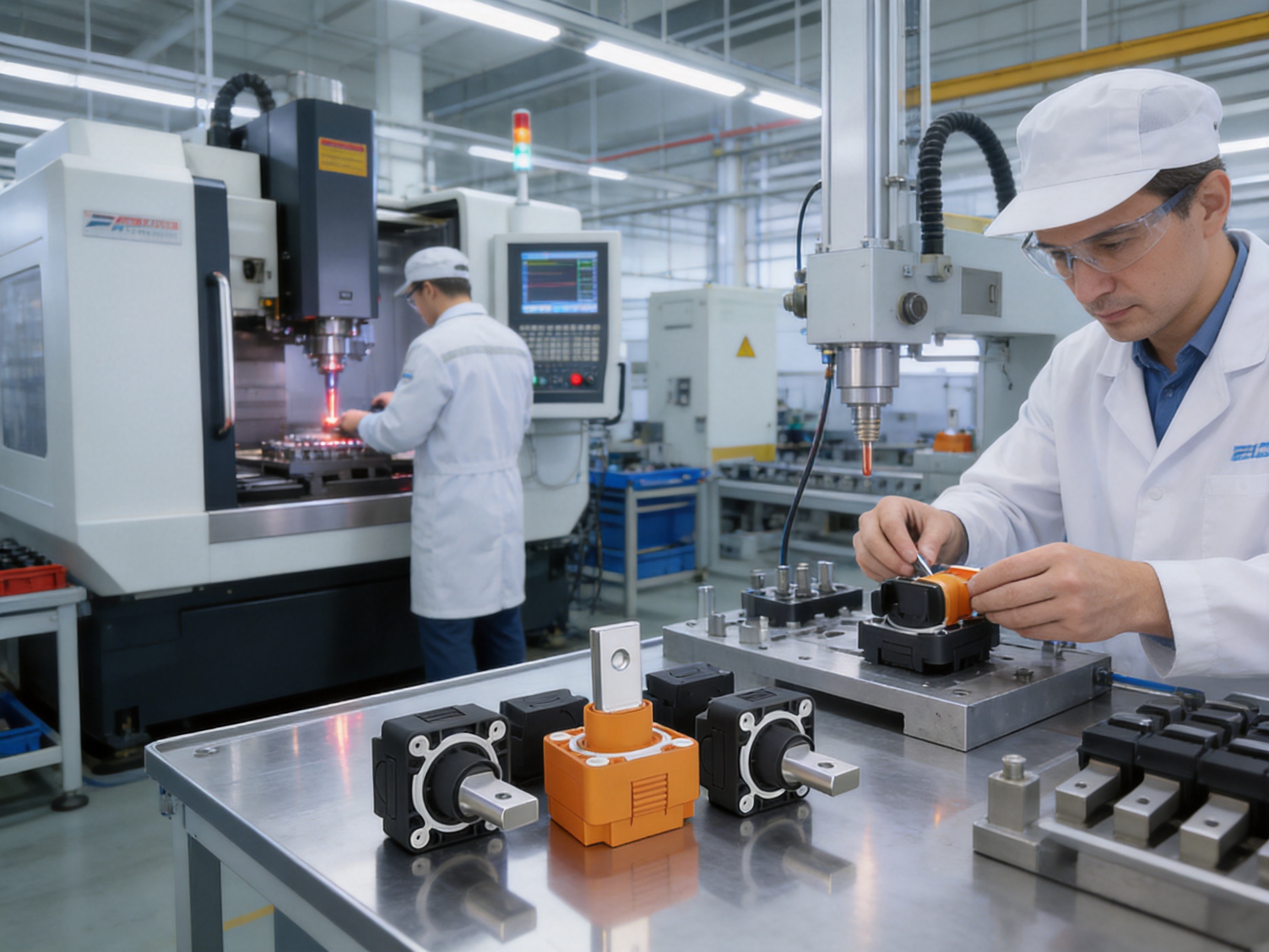
The manufacturer specializes in new energy conductive components, including high-voltage copper foil soft connections, special-shaped soft connections, battery soft connections, and related precision connection products. This specialization provides a strong technical foundation for developing high-current battery terminals and other power transmission components.
Experience in New Energy Components
Battery connection products must satisfy several requirements at the same time. They must conduct high current, withstand voltage, tolerate thermal cycling, maintain mechanical integrity, and fit within increasingly compact equipment. Experience in battery soft connections and conductive components helps the manufacturer understand these combined requirements rather than treating the terminal as an isolated hardware item.
The company’s product development activities cover material selection, precision machining, testing, and verification. This broad capability can support the transition from a basic component concept to a production-ready part with defined performance characteristics.
Polymer Diffusion Welding and Laser Technology
The company has developed technology and patents related to polymer diffusion welding and laser processes. These technologies are relevant to modern battery connection manufacturing because they can support precise joining, controlled heat input, and reliable interfaces between conductive and insulating structures.
Laser technology can be used in suitable production processes for accurate cutting, welding, marking, and component preparation. Controlled laser processing may reduce dimensional variation and help create repeatable products. Polymer diffusion welding can support the formation of integrated insulating or structural components where controlled bonding performance is required.
Manufacturing methods must always be selected according to the specific geometry, material combination, production volume, and required validation standards. The value of advanced equipment is realized when it is combined with process control, trained personnel, appropriate inspection, and documented quality procedures.
Professional Equipment and Technical Teams
The manufacturer brings together experienced engineers and technical teams and operates professional production equipment. This combination supports product design, process optimization, prototype development, production engineering, and technical service.
For OEM customers, engineering support can be particularly important. Energy storage manufacturers may require adjustments to mounting dimensions, conductor geometry, cable interfaces, insulation features, or packaging. A supplier with internal design and manufacturing capabilities can respond more efficiently than a trading company that depends entirely on external production.
Quality and Consistency
High-current connectors must be consistent from one production batch to another. Variation in plating thickness, conductor dimensions, molding quality, screw fit, insulation geometry, or contact surface condition can affect electrical and mechanical performance.
A modern quality management approach should include incoming material inspection, process monitoring, dimensional inspection, electrical testing, insulation testing, dielectric testing, visual inspection, and traceability. While the exact inspection plan depends on the customer’s requirements, these controls provide a practical framework for ensuring that the finished component performs as intended.
Applications
Energy Storage Systems
The primary application is battery energy storage. The connector can be used in battery cabinets, rack-mounted storage systems, containerized energy storage units, and power distribution assemblies. It may serve as an interface between battery modules, busbars, disconnect devices, power conversion systems, and external cable assemblies.
Energy storage systems require dependable bidirectional current transmission. During charging, current flows into the battery, while during discharge, current flows toward the inverter, load, or grid connection. The connector must therefore operate reliably across repeated electrical cycles rather than only during occasional power transfer.
High-Voltage Battery Packs
High-voltage battery packs for industrial equipment, electric vehicles, and specialized mobility systems often require compact, insulated, high-current connection points. A wall-mount terminal can support internal pack layout and provide a defined connection between the battery assembly and external power equipment.
The 1500 V DC rating is suited to high-voltage system designs, subject to the complete system’s insulation coordination, creepage and clearance requirements, and applicable certification rules. The final battery pack must also include appropriate contactor control, pre-charge circuitry, fuses, monitoring, service disconnects, and fault protection.
Electric Vehicles and Electrified Equipment
Electric vehicles and industrial electric equipment depend on efficient connections between battery modules, inverters, motors, charging systems, and auxiliary power units. High-current terminals must withstand vibration, thermal cycling, and repeated load changes.
The connector may be considered for suitable vehicle or equipment subassemblies where its environmental and mechanical characteristics meet the application requirements. Qualification testing should include vibration, shock, temperature cycling, humidity, salt spray where relevant, current cycling, and insulation verification.
Solar Power Generation
Solar power systems frequently use battery storage to balance generation and demand. The connector can support the high-current DC side of solar-plus-storage installations, including battery cabinets, DC combiner sections, and power conversion equipment.
Outdoor solar facilities may experience strong sunlight, rain, dust, large day-night temperature differences, and seasonal weather changes. The connector’s IP67 protection and wide operating temperature range are useful characteristics, although the installer must verify ultraviolet exposure, enclosure protection, cable routing, and long-term environmental compatibility.
Industrial Power Distribution
Industrial facilities use high-current DC connections in backup power systems, automation equipment, welding systems, material-handling machinery, and specialized power supplies. A robust insulated terminal can help improve safety and simplify the layout of high-current distribution equipment.
In industrial environments, the connector should be selected with consideration for vibration, chemical exposure, cleaning methods, electromagnetic compatibility, available space, and maintenance procedures. The use of standardized components can help reduce replacement time and simplify spare-parts management.
System Integration Recommendations
Choose the Correct Current Rating
The current rating should be based on continuous current, expected overload, peak current duration, ambient temperature, enclosure ventilation, cable routing, and duty cycle. Battery systems may operate at a high current for long periods, so a short-duration laboratory rating may not represent actual field conditions.
Designers should evaluate the temperature rise of the connector, busbar, cable lug, cable, and adjacent components. The weakest thermal element often determines the safe current of the complete connection path.
Maintain Correct Contact Surfaces
Contact surfaces should be clean, flat, and free from oil, dust, burrs, and excessive oxidation. The installer should avoid unnecessary abrasion that could remove protective plating. If cleaning is required, the method should be compatible with the nickel surface, insulation materials, and system safety procedures.
Contact areas should be protected from accidental contamination during assembly. After installation, the connection should be inspected for correct seating, alignment, and fastener engagement.
Use Controlled Torque
Specified tightening torque should be followed using an appropriate torque tool. The stated values are M8 at 12 N·m, M10 at 30 N·m, and M4 at 2 N·m for the listed configurations. These values should be confirmed against the final product drawing and application requirements before installation.
Torque should not be treated as a substitute for correct mechanical design. If a busbar is misaligned or a cable is pulling sideways on the terminal, tightening the fastener more firmly will not solve the underlying problem. Proper alignment and support are required.
Provide Cable and Busbar Support
Large conductors should be supported independently of the connector. Cable clamps, busbar brackets, and enclosure supports should control movement caused by vibration, transportation, thermal expansion, and service activity.
The cable bending radius should be respected, particularly near the connector. Excessively tight bends can transfer force to the terminal and cable lug. Busbars should likewise be supported at suitable intervals and should not be forced into position by the connector hardware.
Consider Thermal Management
Low contact resistance reduces heat generation, but it does not eliminate the need for thermal design. The enclosure should provide sufficient ventilation or cooling for the expected load. Nearby battery cells, insulation materials, fuses, contactors, and electronic components may have different maximum operating temperatures.
Thermal imaging, temperature sensors, or other monitoring methods may be used during prototype validation and commissioning. Testing should be performed under representative current, ambient temperature, enclosure conditions, and operating duration.
Inspection, Testing, and Maintenance
Before energization, installers should inspect the connector housing for cracks, deformation, contamination, or damage caused during transport. The conductor interface should be checked for correct alignment and full engagement. Fasteners should be verified for the required torque, and cables should be inspected for correct crimping and support.
Electrical inspection may include continuity testing, contact resistance measurement, insulation resistance testing, and dielectric withstand testing. Test procedures must be appropriate for the voltage rating and must account for connected electronics that could be damaged by test voltage.
During scheduled maintenance, technicians should look for discoloration, signs of overheating, loose fasteners, damaged insulation, water ingress, corrosion, or unusual odor. A change in temperature at a connection under normal load may indicate increased resistance or a developing mechanical problem.
Maintenance intervals depend on the operating environment and system design. Outdoor installations, high-vibration equipment, and systems subject to frequent load changes may require more frequent inspection than stationary indoor systems in controlled conditions.
OEM and Custom Manufacturing Support
Battery and energy storage manufacturers often need more than a standard catalog component. They may require a particular mounting footprint, busbar position, cable exit direction, insulation geometry, current configuration, or enclosure interface. A supplier with design and production capabilities can support these requirements through OEM and customized manufacturing services.
Customization may involve conductor dimensions, hole positions, mounting features, insulation shapes, terminal orientation, labeling, packaging, or assembly instructions. Any modification should be evaluated for electrical clearance, mechanical strength, thermal performance, sealing, manufacturability, and inspection requirements.
The manufacturer’s focus on conductive components, battery connections, precision processing, and new energy applications supports cooperation on customized projects. Its engineering resources and production experience can help customers move from drawings and samples to stable mass production.
For an effective OEM project, customers should provide expected current and voltage, conductor dimensions, installation environment, required temperature range, cable specifications, mechanical loads, target service life, applicable standards, annual demand, and validation requirements. Clear technical information helps reduce development cycles and prevents misunderstandings during sample approval.
Company Manufacturing and Industry Strengths
Zhejiang Zhongyan New Energy Co., Ltd. is a high-tech enterprise focused on conductive components and precision connection solutions for new energy and power applications. Its product scope includes high-voltage electrical copper foil soft connections, special-shaped flexible connections, battery soft connections, and other components used in power transmission and distribution, electric vehicles, rail transit, communications, and energy storage.
The company was established in 2022 and has developed technical capabilities in battery connection products and related new energy components. Its engineering organization covers material science, precision machining, testing, verification, and product development. This interdisciplinary structure is valuable because high-current connection products must be optimized across several technical areas at once.
The company has also pursued independent technology development in polymer diffusion welding and laser processing. These capabilities support precision manufacturing and can be applied to products requiring stable conductive paths, reliable insulation integration, and controlled production quality.
With modern production and quality management systems, the company aims to provide stable and consistent products and services. Its development strategy includes expanding into lithium battery manufacturing and integrated battery cell and connection system design. This direction reflects the growing importance of closely coordinated battery cells, conductors, insulation, thermal management, and monitoring systems.
The company reports cooperation with leading enterprises in the battery and automotive sectors. Such industry experience can help strengthen understanding of high-volume production, stringent quality requirements, traceability, and application-specific validation.
Frequently Asked Questions
What is the main purpose of the Copper Bar Connector?
The connector is designed to create a high-current, insulated connection between copper busbars, large power cables, battery systems, and energy storage equipment. It is suitable for wall-mounted installation and is intended for high-voltage DC applications.
What materials are used?
The insulation shell is made from PA66, while the conductor is made from T2Y pure copper with nickel plating. The copper provides high conductivity, and the nickel surface improves corrosion resistance and contact durability.
What current ratings are available?
The listed configurations include 200 A, 250 A, 300 A, 350 A, 400 A, 450 A, and 600 A. The appropriate rating depends on the selected model, busbar size, cable size, ambient conditions, and system duty cycle.
What voltage can the connector support?
The stated rated voltage is 1500 V DC. The complete installation must also satisfy the required insulation coordination, creepage, clearance, testing, and safety requirements of the battery or energy storage system.
What busbar sizes are compatible?
The listed compatible busbar sizes are 20 × 4 mm, 25 × 6 mm, and 30 × 10 mm. The correct size depends on the current configuration and the mechanical requirements of the application.
What cable sizes are supported?
Depending on the model, the compatible cable sizes are 50 mm², 70 mm², 95 mm², 120 mm², 150 mm², and 185 mm². Cable selection should also consider current capacity, insulation, temperature, bending radius, and installation method.
Is the connector suitable for outdoor energy storage?
It is designed with IP67 protection and an operating temperature range of -40°C to 125°C, making it suitable for many outdoor and harsh-environment applications. Correct sealing, cable installation, enclosure design, and environmental validation remain necessary.
What is the specified contact resistance?
The specified contact resistance is no greater than 0.5 mΩ under the stated test condition of 100 mA. Actual system performance depends on correct installation, clean contact surfaces, proper torque, conductor alignment, and operating conditions.
What tightening torque should be used?
The listed values are M8 at 12 N·m, M10 at 30 N·m, and M4 at 2 N·m, depending on the configuration. The final product drawing or technical instruction should always be checked before assembly.
Does UL94 V-0 mean the complete battery system is fireproof?
No. UL94 V-0 describes the flame-retardant performance of the specified insulating material under a defined test method. Complete battery safety also depends on cell design, protection circuits, thermal management, enclosure construction, monitoring, and emergency response systems.
Can the connector be customized?
OEM and customized manufacturing may be available for suitable projects. Potential customization areas include conductor geometry, mounting dimensions, insulation shape, terminal orientation, cable interface, labeling, and packaging. Each change must be reviewed for electrical, mechanical, thermal, and manufacturing performance.
How should the connector be maintained?
Maintenance should include visual inspection for damage, overheating, corrosion, water ingress, and loose hardware. Electrical testing may include contact resistance and insulation verification where appropriate. Maintenance personnel must follow high-voltage safety procedures and isolate the system before inspection.
Conclusion
The Copper Bar Connector is a purpose-designed component for high-current and high-voltage energy storage applications. Its combination of T2Y pure copper, nickel plating, PA66 insulation, low specified contact resistance, 1500 V DC rating, IP67 protection, UL94 V-0 flame retardancy, and wide operating temperature range gives it a strong position in demanding power connection environments.
The product family covers multiple current levels and conductor sizes, allowing designers to select an appropriate configuration for battery cabinets, energy storage systems, electric vehicles, solar power installations, and industrial power equipment. The wall-mount structure, defined mounting hardware, and compatible busbar and cable options support practical assembly and maintenance.
Compared with basic uninsulated joints, low-current terminals, or improvised cable-to-busbar connections, the connector offers a more integrated approach to electrical conduction, mechanical attachment, insulation, and environmental protection. Its benefits are maximized when the connector is correctly matched to the full current path and installed with suitable torque, conductor support, thermal management, and inspection procedures.
The manufacturer’s specialization in new energy conductive components, technical experience in battery connections, advanced polymer and laser processing capabilities, and focus on precision manufacturing provide a foundation for both standard products and customized OEM solutions. For energy storage and high-voltage battery manufacturers seeking stable, efficient, and professionally engineered connection components, this Copper Bar Connector is a practical option for modern power systems.
References
1. IEC 60529, Degrees of Protection Provided by Enclosures, International Electrotechnical Commission.
2. UL 94, Tests for Flammability of Plastic Materials for Parts in Devices and Appliances, Underwriters Laboratories.
3. IEC 60664-1, Insulation Coordination for Equipment within Low-Voltage Systems, International Electrotechnical Commission.
4. IEC 62477-1, Safety Requirements for Power Electronic Converter Systems and Equipment, International Electrotechnical Commission.
5. IEC 62619, Secondary Cells and Batteries Containing Alkaline or Other Non-Acid Electrolytes—Safety Requirements for Secondary Lithium Cells and Batteries for Use in Industrial Applications, International Electrotechnical Commission.
6. ASTM B170, Standard Specification for Oxygen-Free Electrolytic Copper—Refinery Shapes, ASTM International.
7. Product technical information supplied for the Copper Bar Connector, including electrical ratings, material specifications, mounting requirements, busbar compatibility, cable compatibility, and environmental performance.
8. Manufacturer-provided information concerning conductive component manufacturing, battery connection technology, precision processing, polymer diffusion welding, laser technology, and OEM development capabilities.
Product: Copper Bar Connector

Driven by the development of new energy and aiming for "zero carbon".
Copyright © Zhejiang Zhongyan New Energy Co., Ltd. All Rights Reserved.
