 English
 Español

High-Current Flexible Busbar Connectors for Electric Vehicle Battery Packs
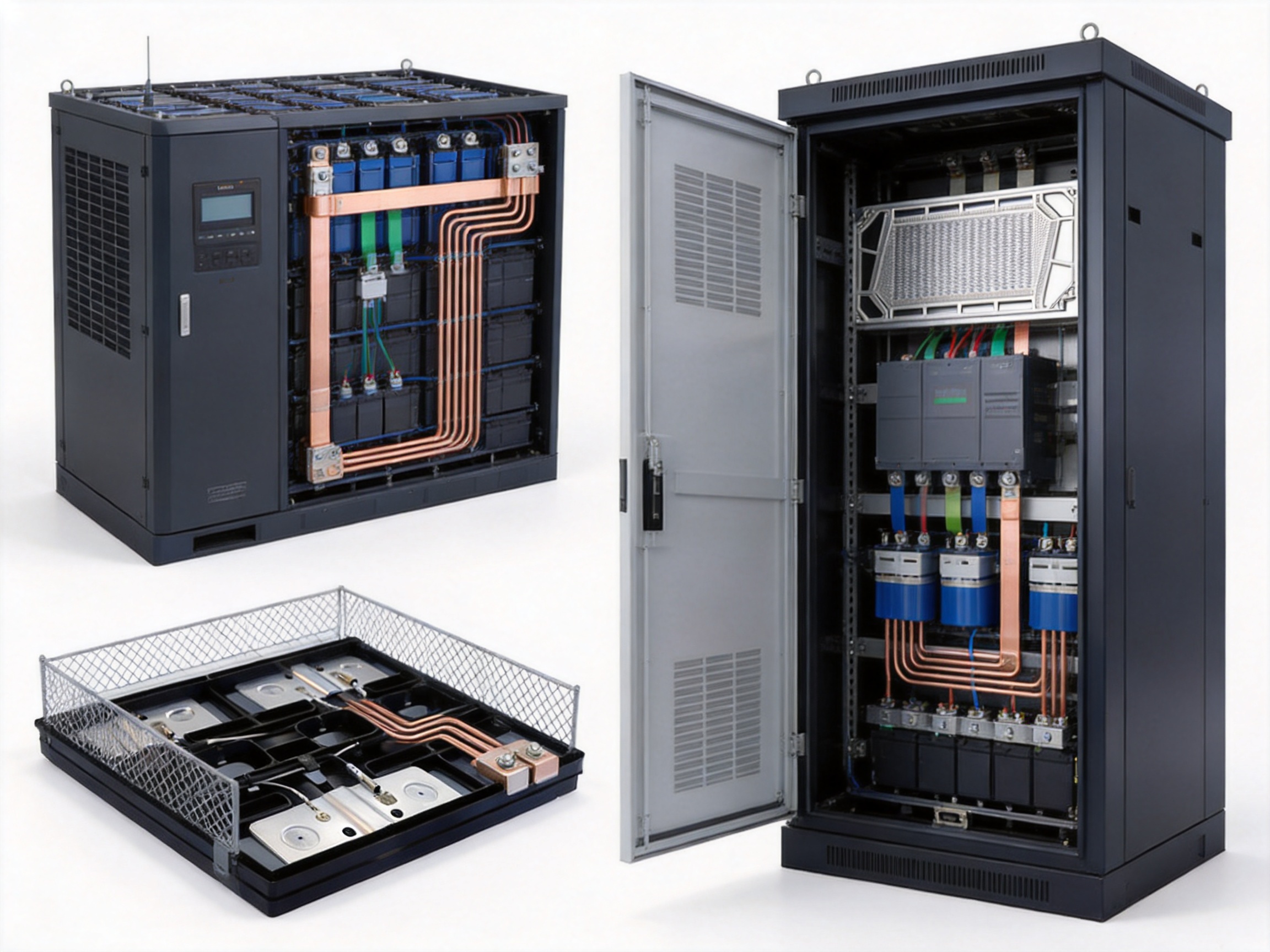
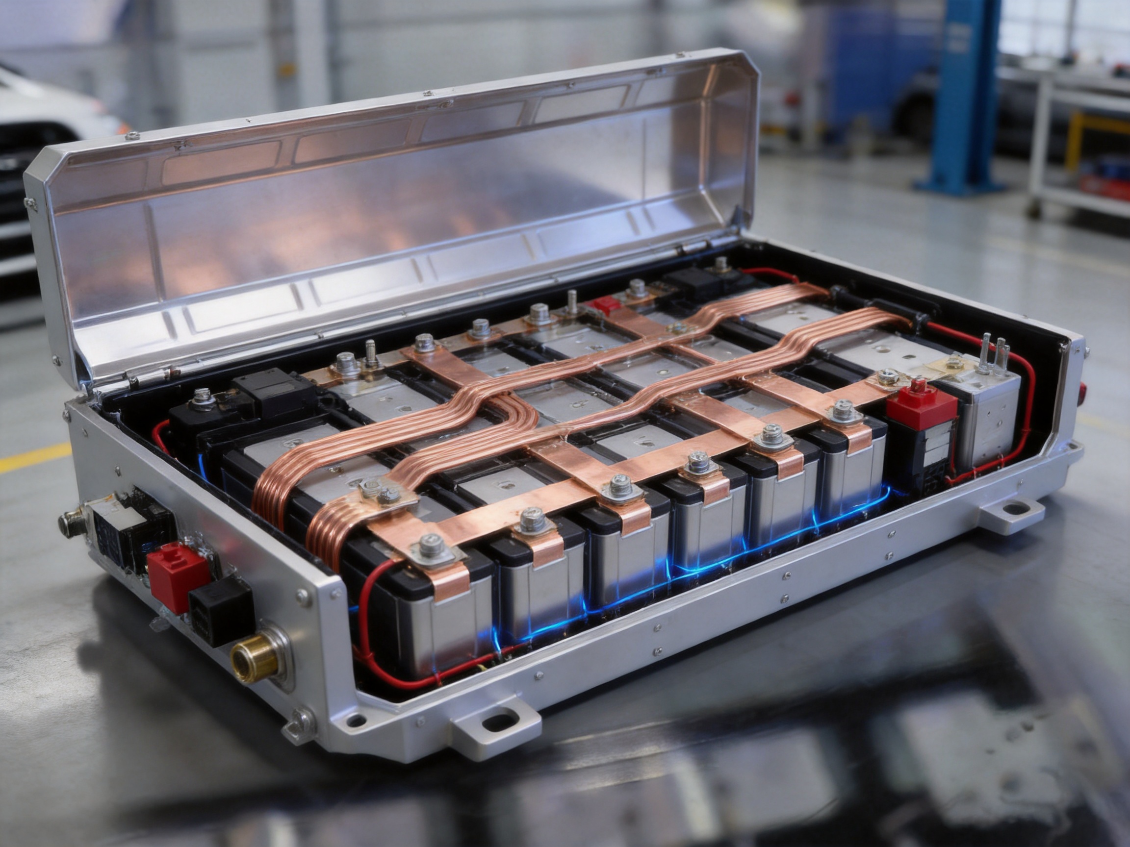
Electric vehicle battery packs require electrical connection components that can carry substantial current, tolerate continuous vibration, manage heat, and fit into increasingly compact mechanical spaces. A high-current flexible busbar connector is one of the most important components in this system. It links battery cells, modules, contactors, switches, inverters, converters, and other power-conversion equipment while maintaining a stable and low-resistance electrical path.
Unlike ordinary rigid copper bars, flexible busbar connectors can absorb movement, compensate for installation tolerances, and reduce mechanical stress transferred to battery terminals. These characteristics make them particularly suitable for electric vehicles, hybrid vehicles, battery energy storage systems, new energy power-grid equipment, industrial power supplies, and high-current distribution assemblies.
The product discussed in this article is a customized high-current flexible busbar connector designed for new energy vehicle battery packs. It uses T2 copper or tinned copper as the conductor, with optional halogen-free insulation. Depending on the design, it can be produced with welded or crimped terminals, section areas from 10 mm² to 1,200 mm², current ratings from 50 A to 2,500 A, operating temperatures from -40°C to 125°C, and withstand-voltage ratings from 600 V to 1,000 V.
Its value extends beyond current conduction. A carefully engineered flexible busbar is also a thermal-management element, a mechanical interface, a space-saving component, and a reliability safeguard. Its geometry, material selection, joining technology, insulation system, and inspection process all influence battery-pack safety and service life.
1. The Role of Flexible Busbars in New Energy Battery Systems
An electric vehicle battery pack contains multiple cells and modules connected in series, parallel, or a combined series-parallel arrangement. The connection system must distribute current evenly, minimize power loss, and maintain electrical integrity during charging, acceleration, regenerative braking, and fault conditions.
In a typical high-voltage battery pack, flexible busbar connectors may be used between battery modules, at module output terminals, around contactors, near current sensors, and in links connecting the battery pack to the inverter or vehicle power-distribution system. The exact configuration depends on the battery architecture, voltage class, available installation space, thermal design, and required current capacity.
Rigid busbars are useful where the connection geometry is fixed and mechanical movement is minimal. However, battery packs are exposed to road vibration, thermal expansion, assembly variation, electromagnetic forces, and repeated changes in operating temperature. A rigid connection may transfer these stresses directly to terminals, weld points, or threaded interfaces.
A flexible busbar introduces controlled compliance into the power circuit. Its laminated, braided, multi-layer, or specially formed structure can accommodate limited movement without compromising the required current path. This helps reduce stress concentration and supports more stable operation over the life of the battery pack.
Flexibility must not be confused with weakness. A professionally designed flexible busbar is engineered to balance bending capability, electrical conductivity, temperature rise, mechanical strength, insulation performance, and manufacturing repeatability. The product must flex in the intended direction and within the specified radius while resisting unwanted deformation during installation and operation.
1.1 Electrical continuity and low resistance
The primary function of the connector is to provide a continuous, low-resistance path between two electrical points. Low resistance reduces voltage drop and limits power loss. It also reduces heat generation according to the relationship between current, resistance, and power dissipation.
At high current, even a small increase in resistance can result in significant heat. For this reason, conductor cross-section, joint quality, terminal geometry, surface condition, and contact pressure must be controlled carefully. Copper is widely selected because it combines high electrical conductivity, good thermal conductivity, ductility, and compatibility with many joining processes.
1.2 Mechanical compliance
Battery modules and connected equipment may move relative to each other because of vibration, thermal expansion, enclosure deformation, or assembly tolerances. Flexible busbars can absorb a portion of this movement and reduce the load on connected terminals.
Mechanical compliance is especially valuable in vehicle applications. A connection that performs well in a stationary laboratory may experience repeated dynamic stress in a vehicle. The busbar must therefore be designed for the actual vibration environment, installation direction, bend radius, and expected service life.
1.3 Thermal and spatial efficiency
The flat structure of a flexible busbar can provide a large conductive area in a compact profile. This supports heat dissipation while allowing the connection to pass through restricted spaces. In a battery pack, where every millimeter can influence energy density and enclosure size, a flat low-profile connection can offer a significant packaging advantage.
Compared with a collection of round cables, a flat busbar can provide a more predictable route, lower occupied volume, and easier integration with module covers or protective barriers. Its shape can also be customized to follow the contours of a battery assembly.
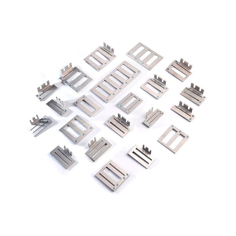
New Energy Vehicle Battery Packs Connector
2. Product Construction and Main Technical Characteristics
The flexible busbar connector can be manufactured in a variety of profiles to suit different battery-pack designs. Its main construction elements include a conductive body, terminal sections, optional insulation, and joining or forming features. The final configuration is developed according to electrical, mechanical, thermal, and installation requirements.
2.1 T2 copper and tinned copper conductors
T2 copper is commonly selected for high-current busbars because of its strong combination of conductivity, formability, and availability. It can be cut, stacked, formed, welded, drilled, punched, or otherwise processed into the required configuration. Its ductility is also helpful when the product must accommodate repeated flexing or controlled forming.
Tinned copper may be selected when enhanced surface protection, solderability, or improved resistance to certain environmental conditions is required. The tin layer can help protect the copper surface from oxidation and support a more stable interface in appropriate applications. The specific coating thickness, surface treatment, and application method should be matched to the operating environment and joining process.
Material selection should consider more than nominal conductivity. The designer must also evaluate operating temperature, corrosion exposure, contact compatibility, joining temperature, mechanical loading, and the requirements of the surrounding battery enclosure.
2.2 Insulation options
Flexible busbars may be supplied bare, partially insulated, or fully insulated. For battery-pack applications, insulation can reduce the risk of accidental short circuits, simplify routing, and improve protection against contact with adjacent conductive components.
Halogen-free insulating materials are available for designs that require reduced halogen content or specific environmental and safety characteristics. The insulation system can be selected according to operating temperature, voltage, abrasion exposure, flexibility, flame behavior, chemical environment, and required dielectric strength.
A properly designed insulation layer should remain securely attached during bending and assembly. It should not crack, peel, or become excessively brittle at low temperatures. It must also withstand the thermal conditions produced by continuous current and temporary overloads within the approved operating range.
2.3 Welded and crimped terminals
Terminal construction is one of the most important factors in busbar reliability. Welded terminals can create a compact, highly integrated connection when the materials and process parameters are correctly controlled. Crimped terminals can provide a practical mechanical and electrical interface for bolts, studs, or other connection hardware.
The preferred terminal method depends on the busbar structure, copper thickness, required current, assembly sequence, available equipment, and customer specifications. A terminal must maintain stable conductivity while resisting loosening, cracking, fatigue, and local overheating.
Terminal holes, slots, bends, and contact surfaces should be designed with appropriate edge distances and radii. Sharp transitions can increase stress concentration, while inadequate contact area can produce excessive current density. Professional manufacturing engineering is therefore essential even when the basic busbar shape appears simple.
2.4 Operating range and capacity
The product range supports operating temperatures from -40°C to 125°C and withstand-voltage levels from 600 V to 1,000 V, subject to the selected materials, insulation design, and validation results. Section areas can range from 10 mm² to 1,200 mm², while current ratings can range from 50 A to 2,500 A.
These figures represent a broad customization range rather than a universal rating for every design. Actual current capacity depends on conductor dimensions, allowable temperature rise, ambient temperature, installation method, airflow, duty cycle, parallel paths, insulation limitations, and connection details.
A reliable supplier should establish the rating through engineering calculation and testing rather than assigning a current value based solely on cross-sectional area. The same conductor may perform differently in open air, inside a sealed battery enclosure, near heat-generating components, or in a tightly packed laminated assembly.
3. Advantages Compared with Conventional Connection Methods
Flexible busbar connectors compete with rigid copper bars, conventional cable assemblies, braided straps, and other laminated or formed conductors. Each solution has an appropriate application, but flexible busbars offer several advantages for modern battery-pack designs.
3.1 Greater tolerance to vibration and movement
Vehicle battery systems experience continuous vibration and shock. A rigid bar can transmit these loads directly to the battery terminal or module housing. Over time, this may contribute to fatigue, loosening, cracking, or damage around the connection point.
A flexible busbar reduces the rigidity of the connection and allows controlled movement. This can help isolate sensitive terminals from vibration and compensate for small dimensional changes. The result is a connection that is better suited to dynamic applications than an unnecessarily rigid conductor.
3.2 Lower installation stress
When rigid parts are forced into alignment, installers may need to apply mechanical pressure or adjust surrounding components. This can create hidden stress that is not visible after assembly. A flexible connector can accommodate moderate misalignment and make the installation process more forgiving.
Reduced installation stress can also improve production consistency. Operators do not need to force every component into precisely identical positions, provided that the flexible busbar remains within its approved bending and routing limits.
3.3 Improved use of restricted space
Battery packs are designed around cells, cooling channels, sensors, contactors, protective barriers, and enclosure structures. Conventional cables may require additional bend radius and routing volume, while rigid bars may be difficult to fit around obstacles.
A customized flat flexible busbar can be formed to follow a defined route. This can reduce unused space and support a more compact connection layout. It may also help battery designers increase usable pack volume without sacrificing electrical performance.
3.4 Efficient heat dissipation
A flat conductor has a broad surface area in relation to its thickness. This may improve heat transfer to the surrounding environment, especially when the busbar is positioned with appropriate clearance and airflow. Better thermal behavior can help control temperature rise during high-current operation.
Thermal performance still depends on the complete assembly. Insulation thickness, enclosure design, contact resistance, nearby components, and cooling conditions all influence the final result. However, a properly dimensioned flat busbar provides a strong starting point for thermal management.
3.5 Reduced electrical loss
High-conductivity copper and carefully controlled joints help minimize resistive loss. Low resistance improves energy efficiency and helps maintain voltage stability under load. In electric vehicles, this can support efficient power transfer during acceleration and regenerative braking.
In stationary energy storage systems, low-loss connections contribute to round-trip efficiency and reduce the amount of heat that must be removed from the enclosure. Over long operating periods, even small efficiency improvements can have a meaningful economic effect.
3.6 Custom geometry and integration
Flexible busbars can be customized by length, width, thickness, bend position, terminal shape, hole pattern, insulation coverage, and connection method. This allows the product to be designed around the customer’s battery architecture instead of forcing the architecture to accommodate a standard part.
Customization can also support integration with current sensors, fuse assemblies, contactors, and module-level connection points. A single engineered component may replace multiple separate pieces, reducing the number of interfaces and simplifying assembly.
3.7 Weight and assembly benefits
A compact conductor layout can reduce the need for additional brackets, clamps, cable supports, and protective hardware. In vehicle applications, the cumulative reduction in connection hardware can support lower component weight and more efficient assembly.
The most important benefit is not always the weight of the copper itself. It may be the reduction in secondary components and labor made possible by a more integrated connection design.
4. Advanced Manufacturing Processes
Flexible busbar quality depends on process control. Copper is conductive and relatively easy to process, but high-current battery connections require tight control over dimensions, joining quality, surface condition, insulation, and cleanliness. Zhejiang Zhongyan New Energy Co., Ltd. focuses on new energy conductive components and has developed capabilities in high-voltage copper-foil soft connections, special-shaped soft connections, battery soft connections, and related precision components.
The company’s manufacturing strengths include experienced engineering personnel, specialized production equipment, product-development capability, process design, and quality-management systems. These capabilities are particularly important for customized components, where stable production requires more than simply copying a drawing.
4.1 Engineering review and design conversion
Production normally begins with a review of the customer’s drawing, electrical specification, installation environment, and expected operating conditions. Engineers evaluate conductor area, current path, terminal geometry, bending direction, insulation requirements, tolerances, and assembly interfaces.
For a new product, design-for-manufacturing analysis can identify potential problems before tooling or production begins. Examples include insufficient bend radii, difficult welding access, excessive local current density, inadequate clearance, sharp corners, or tolerances that are unnecessarily difficult to hold.
Engineering review also helps distinguish functional dimensions from non-critical dimensions. This supports a balanced design in which the important electrical and mechanical features receive appropriate control without increasing cost through unnecessary complexity.
4.2 Copper preparation and precision cutting
Raw copper foil, strip, plate, braid, or other conductor material must be prepared according to the specified construction. Cutting accuracy influences the final width, length, terminal alignment, and layer registration.
Precision cutting helps ensure consistent edge quality and reduces unwanted burrs. Burr control is especially important in insulated high-voltage components because sharp conductive edges can damage insulation or reduce clearance during assembly.
Material traceability is also valuable. Recording material grade, thickness, coating condition, and production batch helps support quality investigation and consistent manufacturing across different orders.
4.3 Layer assembly and forming
Some flexible busbars use multiple copper layers to obtain the required current capacity and flexibility. During layer assembly, the individual pieces must be aligned accurately so that the finished conductor has the correct width, length, and terminal position.
Forming operations may create bends, offsets, stepped sections, or three-dimensional profiles. The process must avoid excessive deformation, layer separation, sharp folds, or damage to the copper surface. Controlled forming is particularly important when the busbar must fit into a predefined battery-pack channel.
In addition to conventional forming, specialized processes may be used for irregular or three-dimensional soft connections. This allows the connector to follow complex routes while maintaining a predictable connection profile.
4.4 Polymer diffusion welding
The company reports independently developed polymer diffusion welding and laser technology patents for the manufacture of new energy precision components. Polymer diffusion welding can be used in specialized soft-connection structures where a stable bond between layers or related materials is required.
The purpose of an advanced diffusion-based joining process is to create a reliable, low-resistance connection with controlled heat input and consistent bonding. Compared with less controlled joining approaches, a well-developed process can reduce the risk of incomplete bonding, excessive local heating, or uneven current distribution.
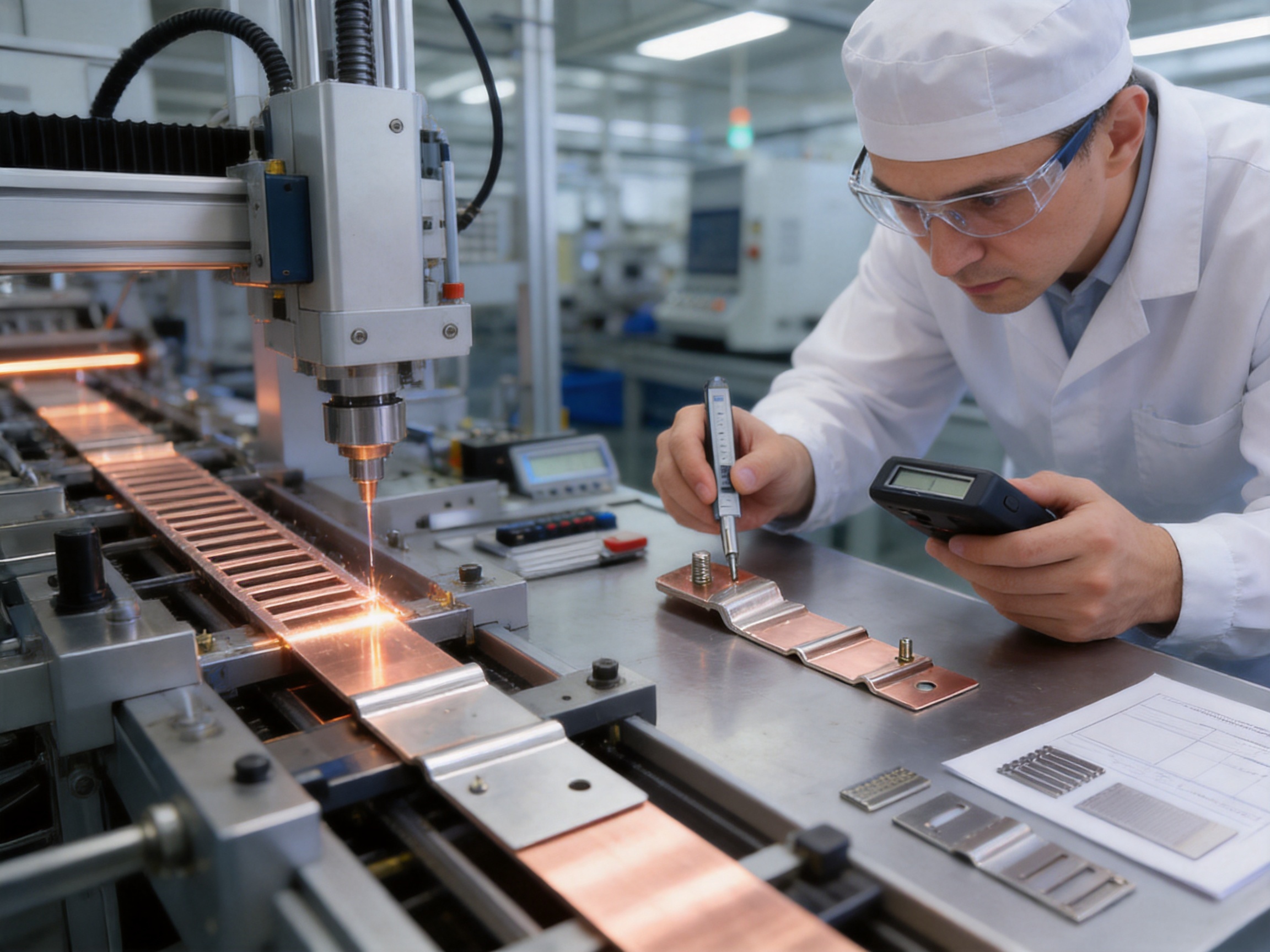
Process parameters must be matched to material composition, layer thickness, surface condition, pressure, temperature, and cycle time. Verification may include visual inspection, dimensional checks, resistance measurement, tensile or peel testing, and section analysis where appropriate.
4.5 Laser welding and precision joining
Laser technology can provide concentrated energy and precise control in selected welding applications. It is suitable for joining certain terminal structures, copper components, and complex conductive assemblies when the equipment and process parameters are correctly matched to the material.
Copper presents particular challenges because it reflects certain laser wavelengths and conducts heat rapidly. Successful laser welding therefore depends on suitable equipment, beam control, surface preparation, energy density, shielding, and monitoring.
A controlled laser process can support narrow heat-affected zones, repeatable weld locations, clean appearance, and high process precision. It may be especially useful where access is restricted or where a conventional welding method would create excessive thermal impact.
4.6 Terminal production and hole processing
Terminal areas may require punching, drilling, milling, bending, welding, plating, or other operations. The final terminal must be dimensionally accurate so that it aligns with the battery module, stud, bolt, or power-distribution interface.
Hole diameter, position, edge distance, flatness, and surface condition directly affect installation quality. A hole that is too tight may make assembly difficult, while excessive clearance can reduce positioning accuracy or increase the risk of uneven contact.
Terminal surfaces should be free of contamination, excessive oxidation, burrs, and deformation. Where plating or tinning is specified, coating consistency and adhesion must be controlled.
4.7 Insulation application
Insulation may be applied through extrusion, heat-shrink processing, molding, coating, lamination, or another suitable method. The selected process depends on the required profile, flexibility, temperature rating, dielectric performance, and production volume.
Insulation coverage must be consistent around bends and terminal transitions. Partial coverage must be carefully defined so that conductive areas remain accessible while protected areas maintain sufficient clearance from adjacent parts.
Inspection should identify pinholes, cracks, exposed conductor in restricted areas, poor adhesion, surface contamination, and dimensional variation. For high-voltage systems, insulation integrity is a critical safety characteristic rather than a cosmetic feature.
5. Quality Control and Reliability Verification
A high-current battery connector should be evaluated as a complete component rather than as a piece of copper alone. Electrical, mechanical, thermal, environmental, and dimensional performance are interconnected. A connector with excellent conductivity but poor terminal strength may still fail in service.
5.1 Dimensional inspection
Dimensional inspection verifies length, width, thickness, bend position, terminal location, hole pattern, flatness, and other drawing requirements. Measurement methods may include calipers, micrometers, gauges, coordinate measurement, optical systems, and dedicated fixtures.
Inspection fixtures can improve repeatability for high-volume production. They also help identify whether variation comes from material preparation, forming, welding, or final assembly.
5.2 Electrical resistance testing
Resistance measurement helps detect inadequate joints, contamination, incomplete bonding, excessive contact resistance, or other defects that could produce heat during service. Four-wire measurement methods may be used when low resistance must be measured accurately.
Testing may be performed across the complete connector or at selected welds and interfaces. Results should be compared with established limits based on design requirements and production capability.
5.3 Current and temperature-rise testing
Current-carrying tests evaluate the behavior of the busbar under defined electrical and environmental conditions. The test may monitor temperature at the conductor body, terminals, welds, and nearby insulation.
Temperature rise is influenced by current, ambient conditions, mounting configuration, airflow, connection resistance, and duty cycle. Testing should therefore reflect the intended installation as closely as possible. A component that passes an open-air test may require additional evaluation when installed inside a sealed pack.
5.4 Dielectric withstand and insulation testing
For insulated busbars used in high-voltage battery systems, dielectric withstand testing helps verify that the insulation can resist the specified voltage without breakdown. Insulation resistance testing may also be used to detect leakage paths or contamination.
The precise test voltage, duration, ramp rate, and acceptance criteria should be established according to the product design, customer requirements, and applicable standards. Testing must be conducted with suitable safety controls.
5.5 Mechanical and vibration testing
Mechanical tests may include terminal pull testing, bend testing, vibration exposure, shock testing, flex-life evaluation, and fastening simulation. These tests help determine whether the connector can withstand assembly and operating loads.
Vibration testing is especially important for electric vehicle applications. The test plan should consider vibration direction, frequency range, acceleration, duration, temperature, and the condition of the attached components.
5.6 Environmental testing
Battery connectors may be exposed to humidity, condensation, temperature cycling, salt or chemical contamination, coolant contact, dust, and other environmental conditions. The appropriate test sequence depends on the vehicle or energy-storage application.
Environmental evaluation can reveal corrosion, insulation degradation, coating failure, loss of flexibility, changes in contact resistance, and mechanical damage. Results should be reviewed together with electrical and dimensional measurements.
5.7 Process control and consistency
Testing individual samples is important, but process consistency is equally valuable. A stable manufacturing process reduces variation between production batches and supports predictable field performance.
Manufacturing controls may include work instructions, equipment calibration, operator training, first-piece inspection, in-process checks, final inspection, nonconformance control, and traceability. These practices help transform engineering specifications into repeatable products.
6. Applications Across New Energy Industries
6.1 Electric vehicle battery packs
Electric vehicle battery packs are the primary application for this product category. Flexible busbars can connect cells, modules, contactors, fuses, current sensors, and external high-voltage terminals. They are suitable for passenger vehicles, commercial vehicles, buses, specialty vehicles, and selected hybrid platforms.
The product can be adapted to different battery chemistries and mechanical architectures. For example, the required current, insulation, terminal arrangement, and thermal design may differ between a compact passenger-vehicle pack and a high-capacity commercial-vehicle system.
6.2 Energy storage systems
Stationary energy storage systems use battery racks, modules, converters, disconnect units, and power-distribution assemblies. Flexible busbars can simplify the connections between these components while accommodating installation variation and vibration from cooling equipment or auxiliary systems.
Because energy storage systems may operate for long periods at steady high current, thermal design and long-term resistance stability are particularly important. The connector should be selected according to continuous current, peak current, enclosure ventilation, maintenance requirements, and fault protection.
6.3 New energy grid equipment
Grid-support equipment, renewable-energy interfaces, power-conditioning units, and high-current distribution cabinets require reliable conductors that can operate under demanding electrical loads. Flexible busbars can be used in compact internal connections where cable routing or rigid-bar assembly would be less convenient.
6.4 Inverters and converters
Inverters and converters often contain high-current semiconductor modules, capacitors, bus terminals, and cooling structures in tightly arranged layouts. A customized flexible connection can reduce assembly complexity and provide a defined electrical path between power stages.
The busbar must be coordinated with electromagnetic, thermal, and mechanical design requirements. In some applications, laminated or closely arranged conductors may also help reduce unwanted loop area and support improved power-electronics performance.
6.5 Power distribution cabinets and UPS systems
Uninterruptible power supplies, industrial power systems, and distribution cabinets benefit from compact high-current connections. Flexible busbars can simplify access around breakers, contactors, and terminal blocks while accommodating maintenance or equipment movement.
For these applications, designers may emphasize current capacity, ease of installation, insulation, serviceability, and resistance to repeated switching or thermal cycling.
| Application | Primary Requirement | Flexible Busbar Benefit | Typical Design Considerations |
|---|---|---|---|
| Electric vehicle battery packs | High current, vibration resistance, compact routing | Stress absorption and customized geometry | Voltage level, insulation, bend radius, terminal arrangement |
| Battery energy storage systems | Continuous current and long service life | Low resistance and simplified assembly | Thermal rise, enclosure ventilation, maintenance access |
| Inverters and converters | Compact high-power interconnection | Short, shaped current path | Clearance, electromagnetic layout, heat dissipation |
| Power distribution cabinets | Reliable internal distribution | Flexible installation around equipment | Terminal compatibility, insulation, serviceability |
| UPS and industrial equipment | Stable current delivery and durability | Reduced cable congestion and mechanical stress | Duty cycle, vibration, temperature, protection rating |
7. Customization and Supply Support
Battery-pack connectors are rarely identical from one project to another. Even products with similar current ratings may differ in terminal spacing, bend orientation, insulation coverage, mounting clearance, and required production quantity. Custom manufacturing is therefore a central part of the product value.
7.1 Design customization
Customization may include conductor cross-section, number of layers, overall length, width, thickness, bend location, terminal shape, mounting holes, welded areas, crimped sections, surface treatment, and insulation material.
Customers can provide a two-dimensional drawing, three-dimensional model, sample, or application description. A capable engineering team can convert the information into a manufacturable design and identify areas requiring clarification before production.
7.2 Prototype and validation support
Prototype quantities allow the customer to confirm fit, routing, installation sequence, electrical performance, and thermal behavior. Early samples can also reveal whether the busbar should be made longer, more flexible, more rigid, differently insulated, or adjusted at the terminal.
Prototype development is most effective when the supplier records design revisions and links test results to the corresponding sample version. This prevents confusion when multiple geometry or material options are evaluated.
7.3 Production scalability
After validation, production may range from small engineering batches to larger recurring orders. A scalable process should maintain critical dimensions and electrical performance across different production volumes.
Production planning includes material sourcing, tooling, equipment capacity, process sequencing, inspection resources, packaging, and delivery coordination. Stable production is especially important when the component is integrated into a vehicle or energy-storage assembly line.
7.4 Packaging and handling
Flexible busbars should be packaged to prevent bending beyond the approved limit, terminal deformation, insulation damage, surface contamination, and mixing of different part numbers. Protective separators, trays, bags, or custom fixtures may be used according to product geometry.
Packaging labels should identify the part number, revision, quantity, batch information, and handling requirements. Clear identification reduces the risk of installing a similar-looking component in the wrong location.
8. Why Manufacturing Expertise Matters
A flexible busbar may appear to be a relatively simple copper component, but its performance depends on many variables that are not visible in a finished photograph. Material thickness, layer alignment, terminal bonding, weld penetration, surface treatment, insulation integrity, and bend behavior all contribute to reliability.
A specialist manufacturer focused on new energy conductive components can build process knowledge across these variables. Experience with high-voltage copper-foil soft connections, battery soft connections, and special-shaped connections helps engineers understand the practical challenges of battery-pack integration.
Zhejiang Zhongyan New Energy Co., Ltd. was established in 2022 and focuses on precision components for new energy applications. According to the company’s provided profile, it has developed capabilities covering materials science, precision machining, testing, and verification. It also reports cooperation or supply relationships with leading enterprises, including BYD, CATL, and Jaguar. Such statements should be evaluated by customers through their own qualification and audit procedures, but they indicate the company’s target market and technical positioning.
The company also reports a development direction extending from battery connection components toward lithium battery manufacturing and integrated cell-and-connection-system solutions. This broader perspective can help connect the design of the electrical interface with the structure and requirements of the battery cell system.
8.1 Engineering and production integration
When design, process development, production, and testing are closely coordinated, problems can be identified earlier. For example, a design team may adjust a terminal radius after production engineers identify forming risk, or modify an insulation boundary after testing reveals an assembly-clearance issue.
This integrated approach is more efficient than treating the supplier as a basic cutting and bending service. It supports better manufacturability, improved repeatability, and more practical cost control.
8.2 Focus on ultra-low internal resistance
The company’s stated use of polymer diffusion welding and laser technologies is directed toward high-reliability, low-resistance conductive components. Ultra-low internal resistance is valuable because it reduces energy loss and limits localized heating.
However, resistance must be considered across the entire current path. A low-resistance weld cannot compensate for an undersized conductor, poor external contact, loose hardware, or inadequate thermal design. The strongest solution combines low-resistance joining with proper system-level engineering.
8.3 Quality and consistency
Modern battery systems require consistency because many connectors may be installed in a single pack or across thousands of packs. Variation in resistance, geometry, or insulation can complicate assembly and create uneven electrical or thermal behavior.
Professional quality systems provide a framework for controlling this variation. They should be supported by actual process data, inspection records, equipment maintenance, and corrective-action procedures.
9. Selection Guide for Engineers and Procurement Teams
Selecting a flexible busbar should begin with the application rather than with a catalog dimension. The following factors should be reviewed before requesting a quotation or approving a design.
9.1 Electrical requirements
Define nominal voltage, maximum continuous current, peak current, duty cycle, overload duration, allowable voltage drop, and acceptable temperature rise. If the current waveform is pulsed or rapidly changing, this should be identified because it may influence thermal and electromagnetic behavior.
9.2 Mechanical requirements
Specify the fixed points, expected movement, vibration level, bend direction, minimum bend radius, installation sequence, and allowable tolerance. The busbar should not be forced into a bend that is tighter than its design allows.
9.3 Environmental requirements
Consider ambient temperature, humidity, condensation, dust, chemical exposure, coolant, salt, ultraviolet exposure where relevant, and the possibility of contact with oils or cleaning agents. The insulation and surface treatment must be compatible with these conditions.
9.4 Interface requirements
Provide terminal-hole dimensions, bolt or stud specifications, contact-surface requirements, sensor interfaces, welding locations, and any required fastening torque. Interface information helps prevent late-stage changes that could affect the entire battery assembly.
9.5 Compliance and documentation
Identify the standards and documentation required for the application. The product information indicates RoHS, UL, and IEC compliance options, but the applicable standard and exact test scope should be confirmed for each design.
Customers may also request material certificates, inspection reports, process-flow documents, control plans, first-article inspection records, and change-control procedures. These documents are particularly useful for automotive and energy-storage qualification.
| Selection Area | Questions to Confirm | Effect on Product Design |
|---|---|---|
| Current | What are continuous, peak, and fault currents? | Determines conductor area, layers, and thermal requirements |
| Voltage | What is the working and test voltage? | Determines insulation, clearance, and dielectric testing |
| Movement | How much vibration or thermal movement is expected? | Influences flexibility, length, and bend geometry |
| Space | What are the available routing and clearance limits? | Determines profile, terminal position, and insulation coverage |
| Environment | Will the connector contact moisture, coolant, salt, or chemicals? | Influences material, coating, sealing, and validation testing |
| Assembly | Will the terminals be welded, bolted, or crimped? | Determines terminal construction and process requirements |
10. Installation and Service Considerations
Even a well-manufactured connector can be damaged by incorrect installation. The busbar should be handled carefully and kept within its specified bend radius. Operators should avoid twisting the conductor, bending it repeatedly at the same location, or using the terminal as a lever to force alignment.
Bolted terminals should be installed with the specified hardware, contact surface, and torque. Excessive torque may deform the terminal or damage the connected component, while insufficient torque may increase contact resistance and permit loosening under vibration.
Insulated areas should remain free from cuts, abrasions, and contamination. If the insulation is damaged during assembly, the component should be evaluated according to the customer’s repair or replacement procedure rather than automatically placed into service.
Routing should prevent contact with sharp edges, moving parts, hot surfaces, and components that may produce electromagnetic or mechanical interference. Adequate clearance should be maintained between high-voltage conductive areas and grounded structures.
During service, technicians should inspect for discoloration, melted insulation, loose hardware, corrosion, unusual odor, terminal deformation, and evidence of overheating. Any change in appearance should be investigated because it may indicate increasing resistance or mechanical stress.
11. Sustainability and Long-Term Value
Efficient conductive components support the broader goal of reducing energy loss in electric transportation and renewable-energy systems. A low-resistance busbar can reduce wasted power during charging, discharging, acceleration, and conversion.
Long service life also contributes to sustainability. A connector that resists vibration, thermal cycling, and corrosion is less likely to require replacement during the life of the battery system. Reliable components can reduce maintenance, downtime, and material consumption.
Copper is a valuable recyclable material, and product design should consider material recovery where practical. Halogen-free insulation options may also support environmental objectives in applications with specific material restrictions.
Sustainability should not be evaluated only by material content. Manufacturing efficiency, defect reduction, packaging, transportation, energy consumption, service life, and end-of-life recovery all contribute to the total environmental impact.
12. Frequently Asked Questions
Q1. What is a flexible busbar connector?
A flexible busbar connector is a high-current electrical conductor designed to provide a compliant connection between two electrical points. It is commonly made from copper foil, copper strip, laminated copper layers, braid, or a related conductive structure. Its flexibility allows it to accommodate vibration, thermal expansion, and installation variation more effectively than a fully rigid bar.
Q2. Why are flexible busbars suitable for electric vehicle battery packs?
Electric vehicle battery packs experience vibration, temperature changes, limited installation space, and high charging or driving currents. Flexible busbars can reduce mechanical stress on battery terminals, provide low-resistance current paths, dissipate heat through a flat structure, and follow customized routes inside the pack.
Q3. What conductor materials are available?
The product specification supports T2 copper and tinned copper. T2 copper provides high conductivity and good formability, while tinned copper can offer improved surface protection and suitable joining characteristics for selected environments. The final material should be chosen according to current, temperature, corrosion, and interface requirements.
Q4. Can the busbar be insulated?
Yes. The product can be supplied with optional halogen-free insulating material or another insulation system selected for the application. Insulation coverage, temperature rating, dielectric strength, flexibility, and environmental resistance should be defined during design review.
Q5. What current range can the product support?
The stated product range is approximately 50 A to 2,500 A. The actual rating depends on conductor cross-section, temperature rise, installation method, ambient conditions, duty cycle, and connection resistance. A project-specific rating should be confirmed through engineering calculation and testing.
Q6. What section areas are available?
The stated section-area range is approximately 10 mm² to 1,200 mm². The required area depends on the current, allowable temperature rise, available space, electrical loss target, and mechanical design.
Q7. Can the terminals be customized?
Yes. Terminal length, width, hole pattern, bend position, welded areas, crimped areas, surface treatment, and connection method can be customized according to the battery-pack interface and customer drawing.
Q8. Is a flexible busbar better than a cable?
Neither solution is universally better. A flexible busbar may provide a flatter profile, more predictable routing, lower occupied volume, and integrated terminal geometry. A cable may be more suitable for long flexible routes or applications requiring extensive movement. The correct choice depends on current, space, bending, environment, and assembly requirements.
Q9. Is a flexible busbar better than a rigid busbar?
A flexible busbar is generally more suitable where vibration, thermal movement, or alignment variation is significant. A rigid busbar may be more economical or structurally appropriate where the geometry is fixed and movement is minimal. Many systems use both types in different locations.
Q10. What testing should be requested?
Typical tests may include dimensional inspection, resistance measurement, current and temperature-rise testing, dielectric withstand, insulation resistance, terminal strength, vibration, thermal cycling, humidity, corrosion, and flex-life evaluation. The exact test plan should be based on the product design and application requirements.
Q11. What information is needed for a quotation?
Useful information includes drawings or three-dimensional models, current and voltage requirements, conductor material, insulation requirements, terminal details, overall dimensions, bend locations, quantity, annual demand, environmental conditions, required standards, and target delivery schedule.
Q12. Can prototypes be produced before mass production?
Prototype production is normally recommended for customized battery connectors. It allows the customer to confirm fit, routing, assembly, electrical performance, thermal behavior, and insulation clearance before final production approval.
Q13. What makes a supplier competitive in this product category?
Important factors include material knowledge, flexible-busbar design experience, precision forming, reliable welding, insulation capability, testing resources, quality systems, production scalability, engineering communication, and the ability to support customization. Competitive pricing is valuable, but it should not be separated from process reliability and long-term product consistency.
Q14. Can these connectors be used in stationary energy storage?
Yes. The same product category can be adapted for battery energy storage systems, power-conversion equipment, distribution cabinets, and related high-current applications. The design should be reviewed for continuous current, enclosure ventilation, thermal rise, maintenance access, and installation conditions.
13. Conclusion
High-current flexible busbar connectors are a critical enabling component for modern battery and power-electronics systems. They combine the conductivity of copper with controlled mechanical compliance, compact geometry, efficient heat dissipation, and customizable terminal arrangements.
For electric vehicle battery packs, these characteristics help address the challenges created by vibration, high current, thermal cycling, restricted space, and demanding assembly requirements. For energy storage systems, inverters, converters, UPS equipment, and power-distribution cabinets, they provide a practical alternative to complex cable assemblies or overly rigid conductors.
The product range described here supports T2 copper or tinned copper conductors, optional halogen-free insulation, welded or crimped terminals, operating temperatures from -40°C to 125°C, withstand-voltage levels from 600 V to 1,000 V, section areas from 10 mm² to 1,200 mm², and current ratings from 50 A to 2,500 A, subject to project-specific validation.
The strongest competitive advantage comes from combining material selection with advanced manufacturing. Engineering review, precision cutting, controlled layer assembly, forming, polymer diffusion welding, laser joining, terminal processing, insulation application, and systematic testing all contribute to a dependable finished product.
Zhejiang Zhongyan New Energy Co., Ltd. positions itself as a specialist in new energy conductive components, including high-voltage copper-foil soft connections, special-shaped soft connections, battery soft connections, and related precision products. Its reported engineering resources, specialized equipment, process-development capabilities, and focus on low-resistance, high-reliability connections provide a foundation for customized battery-pack solutions.
For buyers and engineers, the most effective sourcing approach is to define the electrical, mechanical, thermal, environmental, and compliance requirements at the beginning of the project. With those requirements clearly established, a flexible busbar supplier can develop a connection that fits the battery architecture, performs reliably under high current, and supports efficient long-term production.
References
1. International Electrotechnical Commission, standards and technical guidance for low-voltage and high-voltage electrical equipment.
2. Underwriters Laboratories, safety requirements and evaluation principles for battery systems, power equipment, and electrical insulation.
3. Society of Automotive Engineers, recommended practices for electric vehicle power systems, vibration environments, and high-voltage components.
4. Copper Development Association, technical information on copper conductivity, current carrying capacity, thermal performance, and fabrication.
5. International Organization for Standardization, quality-management principles for manufacturing and supplier process control.
6. International Organization for Standardization, road-vehicle environmental, electrical, and vibration testing guidance.
7. Restriction of Hazardous Substances requirements for electrical and electronic equipment.
8. Manufacturer-provided technical information for flexible busbar connectors, battery soft connections, insulation systems, and precision conductive components.
9. Manufacturer-provided company information concerning engineering capability, polymer diffusion welding, laser technology, new energy component manufacturing, and battery connection-system development.
Product: New Energy Vehicle Battery Packs Connector

Driven by the development of new energy and aiming for "zero carbon".
Copyright © Zhejiang Zhongyan New Energy Co., Ltd. All Rights Reserved.
