 English
 Español

High-Performance 2 m and 3 m Insulated Flexible Copper Busbars for High-Current Electrical Systems
Reliable power distribution depends on conductive components that can carry high current, withstand mechanical and environmental stress, and fit efficiently into increasingly compact electrical equipment. The 2 m and 3 m red copper insulated soft busbar is designed for precisely this purpose. Combining highly conductive copper, a flexible laminated construction, and a flame-retardant insulating layer, it provides a practical alternative to rigid bars, conventional cables, and short connection pieces assembled with multiple joints.
This insulated flexible busbar is suitable for current applications from approximately 125 A to 4,500 A, depending on the selected cross-sectional area, copper thickness, installation conditions, and thermal design. Its long, continuous construction allows engineers and installers to create compact bends, folds, and twists without the limitations associated with rigid copper bars. It is particularly useful where electrical connections must pass through restricted spaces, accommodate vibration, or connect equipment with slightly different alignment positions.
The product is available in 2 m and 3 m lengths, with multiple width and thickness combinations. Red copper versions are offered alongside selected tinned copper versions for applications that require improved surface protection and terminal compatibility. PVC and TPE insulation options can also be selected according to temperature, flexibility, flame-retardancy, and environmental requirements.
Zhejiang Zhongyan New Energy Co., Ltd. manufactures insulated flexible busbars as part of a broader portfolio of conductive components for power distribution, electric vehicles, rail transit, industrial equipment, communications, and energy storage. Its experience in copper foil soft connections, battery connections, precision welding, and new-energy electrical components supports the development of customized busbar products for demanding OEM and project applications.
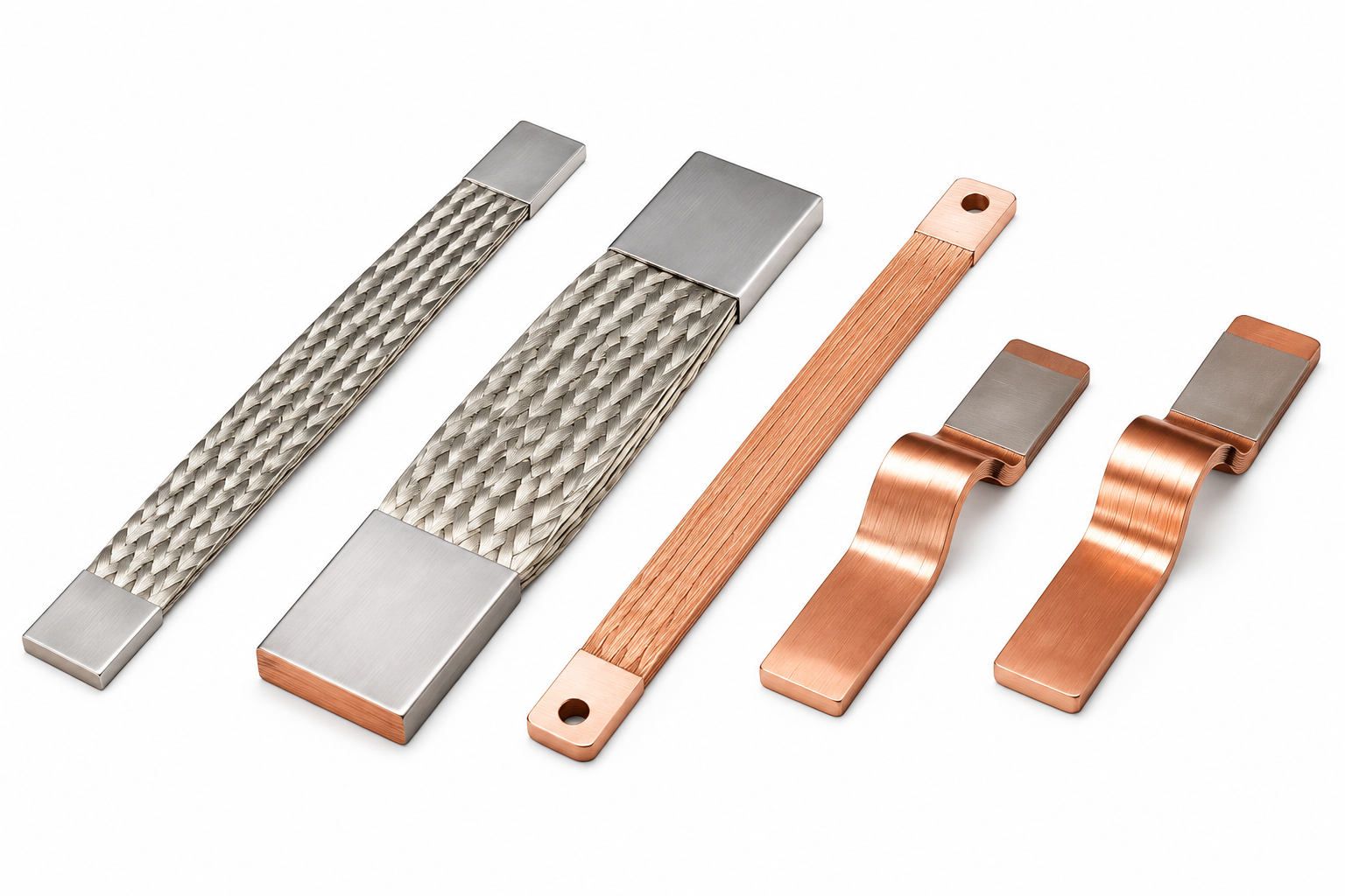
2m/3m Red Copper Insulated Soft Busbar
1. What Is an Insulated Flexible Copper Busbar?
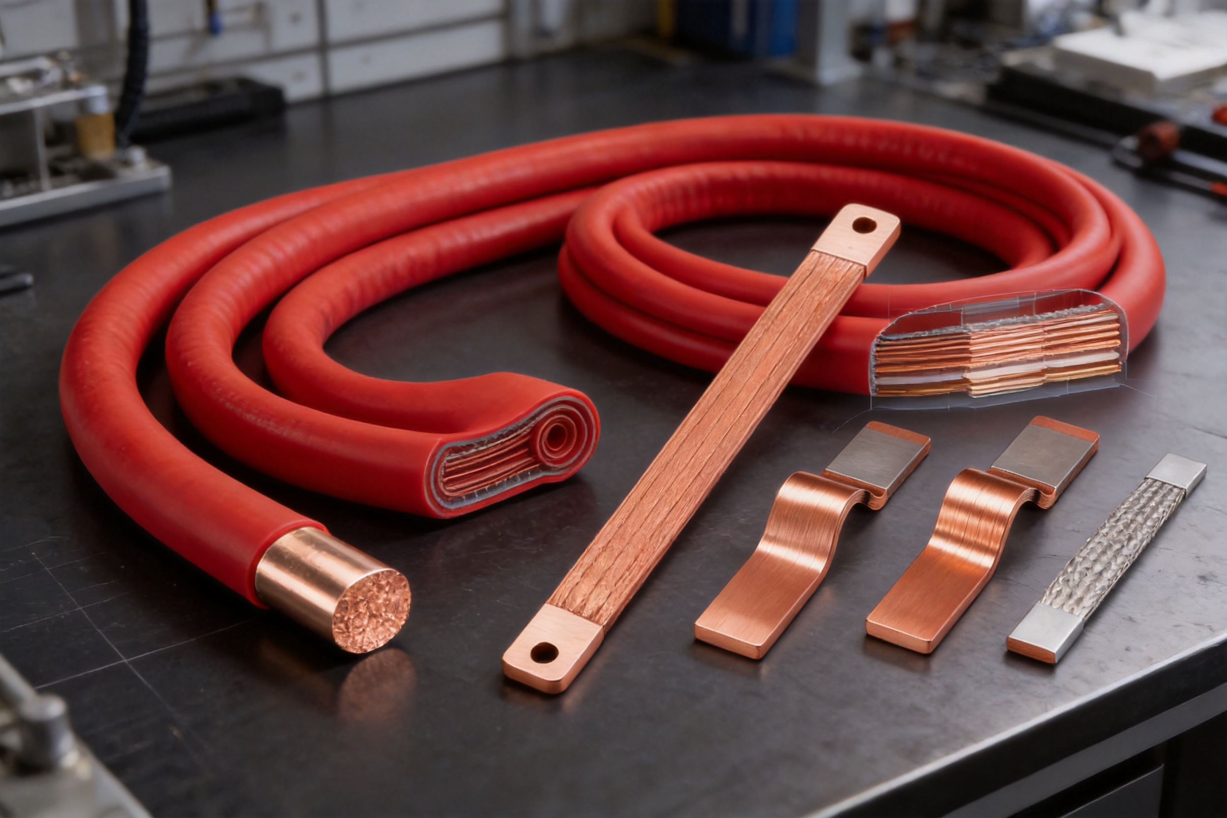
An insulated flexible copper busbar is a flat, laminated electrical conductor covered by an electrically insulating polymer layer. Instead of using a single thick and rigid copper bar, the conductor may be formed from one or more thin copper sheets or laminated copper layers. This construction allows the busbar to carry substantial current while remaining flexible enough to bend, fold, or twist during installation.
The conductor is generally manufactured from annealed electrolytic copper, commonly identified as T2 copper. Copper content may reach 99.9% or higher, while the supplied product information identifies high-purity copper options up to 99.95%. The conductor’s high conductivity reduces resistive power loss and helps control temperature rise under load.
The insulation is applied through extrusion molding. Depending on the required operating temperature and application environment, the insulation can be based on PVC or TPE. Typical colors include red, orange, and black. The red copper product described in this article is commonly supplied with a red-colored insulation or red-copper product identification, while the exact insulation color should be confirmed during technical specification and order review.
The product is not simply a flexible wire. Its broad, flat geometry provides a large conductive cross-section and a relatively low-inductance connection path. Compared with round cables of a similar current rating, a flexible busbar can occupy less space in certain layouts and may provide a more controlled connection between switchgear, transformers, inverters, batteries, charging systems, and distribution equipment.
1.1 Flexible Laminated Construction
The flexible construction is based on thin copper sheets with typical individual thicknesses of 0.5 mm or 1 mm. These layers can move slightly relative to one another during bending, enabling the completed busbar to follow complex installation paths. The result is a connection that is easier to route around terminals, barriers, structural frames, and cooling components.
Flexibility is especially valuable in equipment that experiences vibration or repeated thermal expansion and contraction. A rigid conductor may transfer mechanical stress directly to a terminal, insulator, or equipment bushing. A flexible laminated busbar can absorb a portion of this movement, helping reduce stress at the connection points when correctly supported and installed.
1.2 Continuous Lengths of 2 m and 3 m
Many electrical assemblies require connections longer than a standard short busbar segment. The 2 m and 3 m formats provide additional routing freedom and can reduce the need to connect several short pieces. A continuous length can simplify installation, particularly in distribution panels, busbar trunking layouts, energy-storage systems, and large equipment assemblies.
Longer products can also reduce the number of intermediate joints. Every additional joint introduces possible contact resistance, alignment requirements, fasteners, and inspection points. When the application permits a continuous connection, the 2 m or 3 m design can support a cleaner electrical and mechanical layout.
Long lengths must nevertheless be installed with appropriate support. The busbar should not be allowed to hang from terminals or experience excessive unsupported movement. Engineers should determine bend radii, fixing intervals, terminal preparation, and enclosure clearances according to the current, voltage, temperature, vibration, and short-circuit requirements of the installation.
2. Main Product Advantages
2.1 High Electrical Conductivity
The use of high-purity electrolytic copper gives the busbar a strong electrical performance foundation. The product information identifies copper conductivity of at least 56.2 MS/m for the laminated conductor, equivalent to approximately 97% IACS, while the product description also refers to high-purity T2 copper with conductivity up to 100% IACS. Actual conductivity depends on the copper grade, temper, coating, and product configuration, so the applicable value should be confirmed on the technical datasheet for each order.
High conductivity reduces resistance over the connection length. Lower resistance generally means lower I²R power loss, less heat generation, and improved efficiency in high-current systems. This is important in charging equipment, power conversion systems, data centers, energy-storage installations, and industrial machinery, where even a small reduction in connection loss can contribute to lower operating costs and improved thermal margins.
The flat conductor also provides a broad current-carrying area. The available range includes narrow sections such as 8 mm by 6 mm configurations and larger sections extending to approximately 10 mm by 120 mm in the listed 2 m range. The proper size must be selected based on continuous current, peak current, ambient temperature, enclosure ventilation, installation orientation, allowable temperature rise, and applicable electrical standards.
2.2 Flexibility in Compact Installations
A principal advantage over conventional rigid busbars is the ability to make small-radius bends. The product can be bent, folded, or twisted to produce a compact connection between terminals that are not located on the same plane. This is useful when power must pass around equipment frames, between stacked battery modules, or through limited spaces inside switchboards and converters.
Flexible routing can reduce the overall footprint of an electrical assembly. Designers may be able to shorten the distance between components, eliminate unnecessary rigid elbows, and simplify the arrangement of insulation barriers. This can be particularly valuable in energy-storage systems, electric-vehicle equipment, charging stations, and high-density data-center power distribution.
Flexibility also reduces dependence on highly accurate terminal alignment. Rigid bars often require precise measurements, multiple bends, and custom machining before installation. A flexible busbar can accommodate small positional tolerances, which may reduce fitting time and make field assembly more practical.
2.3 Fewer Splicing Points
A single 2 m or 3 m connection can replace several shorter pieces in suitable applications. Reducing splices can lower the number of bolted or welded interfaces and simplify quality control. Fewer joints may also reduce the potential for loose fasteners, surface contamination, local heating, and increased contact resistance.
This advantage is particularly relevant to high-current systems. At high current, a poorly prepared or insufficiently tightened connection can create a localized hot spot. Long continuous busbar sections do not eliminate the need for correctly made end connections, but they can reduce the number of intermediate electrical interfaces that must be inspected and maintained.
2.4 Integrated Electrical Insulation
The extrusion-molded insulation creates an integrated protective layer around the conductive material. This helps reduce the risk of accidental contact, phase-to-phase short circuits, and unintended contact with grounded metal structures. It can also support improved creepage and clearance management in compact equipment designs.
Typical supplied insulation thicknesses are approximately 1.0 to 1.5 mm for orange insulation and 1.8 to 2.2 mm for black insulation, subject to the selected material and manufacturing specification. The dielectric strength is identified as greater than 23 kV/mm, and the stated withstand-voltage capability is greater than 15 kV to ground and greater than 30 kV between busbars for a 15-minute, 50 Hz test condition. These values should be treated as product reference data and verified against the final configuration and required standard.
Insulation is not intended to replace all system-level protection. The installation must still provide correct spacing, terminal covers, barriers, grounding, overcurrent protection, and enclosure design. However, integrated insulation can significantly simplify the protection of a flexible high-current connection.
2.5 Flame Retardancy and Temperature Performance
The insulation is designed to be self-extinguishing and is identified as UL94 V-0 rated. This flame-retardant performance is valuable in electrical cabinets, battery systems, industrial machinery, and transportation applications where limiting flame spread is an important safety objective.
PVC versions are specified for an operating range of approximately -30°C to +105°C. TPE versions can offer a wider range, identified as approximately -40°C to +135°C. The selection between PVC and TPE should consider the actual continuous temperature, short-term overload conditions, flexibility requirements, exposure to oils or chemicals, low-temperature operation, and applicable fire-performance requirements.
The insulation data also identifies an oxygen index of approximately 30%, tensile strength of at least 20 MPa, and elongation after aging testing of more than 180% under the stated test condition of 135°C for seven days. These characteristics indicate that the insulation is intended to retain useful mechanical performance after thermal aging, although final suitability must be assessed for the specific environment.
2.6 Mechanical Strength and Vibration Resistance
The copper conductor has a stated tensile strength of at least 200 MPa and elongation of at least 30%. These values support the product’s ability to withstand forming and installation operations when appropriate bending procedures are followed.
In equipment exposed to vibration, flexible connections can provide a mechanical advantage over rigid conductors. Rather than concentrating all movement at a terminal, the laminated structure can distribute bending along the connection. This can help protect terminal studs, battery posts, inverter connections, and equipment bushings from excessive mechanical loading.
Mechanical performance depends greatly on installation. The busbar should be bent only within the recommended radius and should not be repeatedly flexed beyond its design capability. Sharp tools, excessive clamping pressure, twisting near the terminal, or damage to the insulation can compromise service life. The use of appropriate end terminals, supports, and protective radii is essential.
3. Comparison with Alternative Connection Methods
3.1 Flexible Busbar versus Rigid Copper Bar
Rigid copper bars are effective for straight, stable, and precisely aligned connections. They provide excellent current capacity and strong mechanical support, but they usually require accurate measurement, cutting, drilling, deburring, bending, and insulation treatment. Any change in equipment layout may require a new bar or additional modification.
The insulated flexible busbar is more adaptable. It can follow a non-linear path and accommodate moderate alignment variation without requiring complex forming equipment at the installation site. It also arrives with insulation already applied, reducing the need for separate wrapping, sleeving, or barrier installation.
Rigid bars may remain preferable for long, unsupported runs, structural busbar systems, or applications where high short-circuit forces require exceptional mechanical bracing. The flexible product is best selected where routing adaptability, compactness, vibration tolerance, and installation efficiency are priorities.
3.2 Flexible Busbar versus Round Cable
Round power cables are widely available and offer excellent flexibility, especially when stranded conductors are used. However, a cable may require larger bending space, special lugs, cable glands, bend supports, and additional separation for heat dissipation. Multiple parallel cables may also be required for very high currents.
A flat flexible busbar can provide a more compact connection in an enclosure. Its broad geometry may make it easier to arrange in layered or laminated power assemblies. It can also offer a visually clear current path and may simplify phase separation when several insulated busbars are routed together.
Cables remain advantageous where long-distance routing, repeated movement, or multidirectional flexibility is required. The correct selection depends on current, voltage, frequency, short-circuit forces, electromagnetic requirements, installation space, and maintenance practices.
3.3 Flexible Busbar versus Short Bolted Links
Short copper links with multiple bolted joints can connect separate portions of an electrical system, but each joint requires appropriate surface preparation and torque control. A longer flexible busbar may reduce the number of connection points and allow equipment to be positioned with greater freedom.
Fewer joints can improve consistency during production and reduce the inspection burden. For OEM manufacturers, this may translate into fewer assembly steps and a lower risk of variation between production units.
4. Technical Specifications and Available Configurations
The listed product family includes multiple conductor widths, thicknesses, and lengths. Descriptions such as “2M6x24x1” generally indicate a 2 m length, 6 mm conductor thickness or layer dimension, 24 mm width, and 1 mm sheet or conductor thickness, although the exact interpretation of the notation should be confirmed with the manufacturer before ordering.
The 2 m range contains configurations from compact sections such as 8 mm by 6 mm by 0.5 mm through larger formats such as 10 mm by 120 mm by 1 mm. The 3 m red copper range includes selected sections from approximately 6 mm by 9 mm by 0.8 mm to 5 mm by 50 mm by 1 mm. The 3 m tinned copper range includes configurations from approximately 2 mm by 20 mm by 1 mm to 10 mm by 40 mm by 1 mm.
| Item | Reference Specification | Application Significance |
| Available lengths | 2 m and 3 m | Supports long, continuous connections and reduces intermediate joints |
| Conductor material | Annealed electrolytic copper, T2 copper; copper content generally at least 99.9% | Provides high conductivity and good forming capability |
| Conductor sheet thickness | Typically 0.5 mm or 1 mm | Allows different current capacities and flexibility levels |
| Reference conductivity | At least 56.2 MS/m for the stated laminated conductor specification | Helps reduce voltage drop and resistive losses |
| Conductor tensile strength | At least 200 MPa | Supports mechanical durability during handling and forming |
| Conductor elongation | At least 30% | Provides useful ductility for flexible installation |
| Insulation materials | PVC or TPE | Enables selection for different temperature and flexibility requirements |
| Insulation thickness | Approximately 1.0–1.5 mm for orange; 1.8–2.2 mm for black, subject to specification | Provides electrical isolation and contact protection |
| Dielectric strength | Greater than 23 kV/mm reference value | Supports high-voltage insulation performance |
| Flame performance | Self-extinguishing; UL94 V-0 reference rating | Helps limit flame propagation in electrical equipment |
| PVC operating temperature | Approximately -30°C to +105°C | Suitable for many industrial and power-distribution environments |
| TPE operating temperature | Approximately -40°C to +135°C | Supports higher-temperature and low-temperature applications |
| Typical current range | Approximately 125 A to 4,500 A, depending on design | Serves low, medium, and high-current connection requirements |
The current rating should never be selected from cross-sectional area alone. Heat dissipation is affected by the number of adjacent conductors, insulation thickness, enclosure ventilation, ambient temperature, installation orientation, duty cycle, and allowable temperature rise. For a final design, the manufacturer and system designer should confirm current-carrying capacity through calculation or testing.
Packaging quantities vary according to product size. Smaller 2 m items may be packaged in quantities of 10, while larger sections may be packaged in quantities of one or two. The 3 m configurations are commonly supplied in packages of two or five. The stated product table includes individual weights ranging from less than 1 kg for smaller sections to more than 20 kg for certain large 2 m sections.
One listed weight entry appears inconsistent with the surrounding data, showing “215” for a 2 m, 5 mm by 20 mm by 1 mm configuration. Because this may represent a formatting or decimal-point issue, the exact unit weight should be confirmed during quotation and order approval.
5. Manufacturing Process and Quality Strengths
5.1 Copper Material Selection
Manufacturing begins with the selection and inspection of copper material. High-purity electrolytic copper is chosen to provide stable conductivity, consistent mechanical properties, and suitable ductility for bending and lamination. Material certificates can be reviewed for copper grade, chemical composition, conductivity, temper, and mechanical performance when required by the project.
Material consistency is particularly important for high-current components. Variations in copper thickness, surface condition, or conductivity can affect resistance, heat generation, and dimensional accuracy. A controlled raw-material process helps provide more consistent performance across production batches.
5.2 Precision Slitting and Forming
Copper sheets are processed into the required widths and thicknesses using precision cutting or slitting equipment. Edge quality is important because sharp burrs can damage insulation, interfere with lamination, or create local stress concentrations during bending. Controlled forming helps maintain dimensional tolerances throughout the length of the busbar.
Depending on the construction, copper sheets may be annealed to improve flexibility. Annealing reduces excessive hardness and supports the repeated forming needed for compact routing. The process must be carefully controlled to avoid unwanted distortion, oxidation, or variation in material properties.
5.3 Lamination and Joining Technology
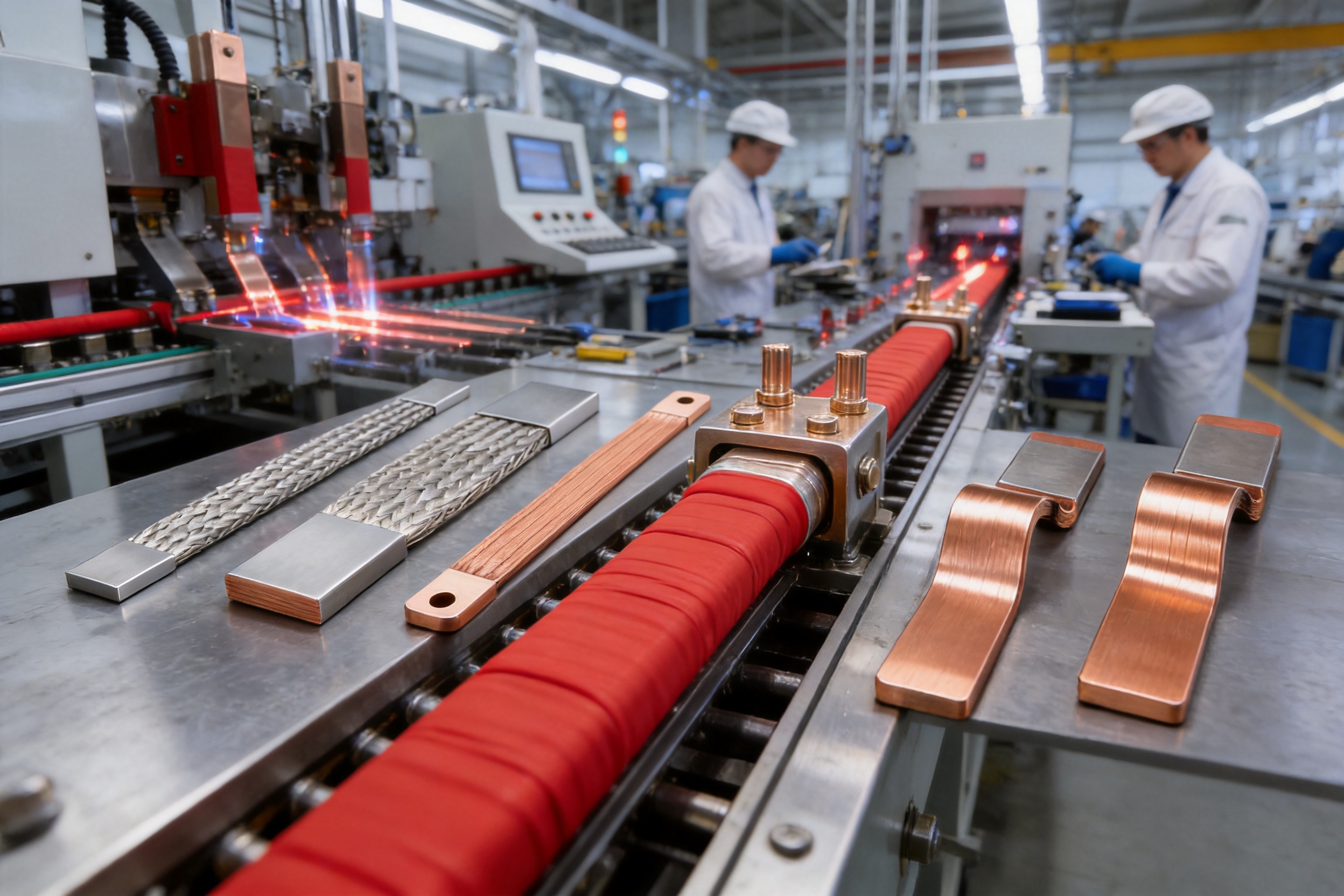
For laminated flexible busbars, the copper layers are assembled and joined to create a stable conductive structure. Zhejiang Zhongyan New Energy has experience in polymer diffusion welding and laser technology for new-energy conductive components. These technologies can support low-resistance, high-reliability connections when applied to appropriate product designs.
Polymer diffusion welding can create a durable connection between conductive layers or associated components while maintaining a compact structure. Laser processing can provide precise, localized joining with limited heat-affected areas when the process is correctly controlled. The selection of joining technology depends on conductor thickness, joint geometry, production volume, mechanical requirements, and electrical performance targets.
Advanced joining processes can provide important advantages over inconsistent manual methods. They can improve repeatability, reduce unnecessary material deformation, and support automated inspection. For battery and power-electronics components, low internal resistance and stable joint quality are essential because local resistance can produce heat under high current.
5.4 Insulation Extrusion
After conductor preparation, insulation is applied through extrusion molding. The copper busbar passes through a controlled die while the selected PVC or TPE compound is applied around the conductive structure. Temperature, pressure, line speed, material flow, and die alignment must be controlled to create uniform insulation thickness.
Stable extrusion is important for both electrical and mechanical performance. Insufficient insulation can reduce dielectric strength and creepage protection, while excessive variation can affect dimensions, bending behavior, and installation clearance. Online or in-process inspections may be used to monitor outer dimensions, surface quality, color, and insulation continuity.
The extrusion process also allows the manufacturer to provide long, continuous insulated lengths. This is one of the main reasons a 2 m or 3 m product can be supplied as a finished connection rather than as a bare copper component requiring separate insulation work after installation.
5.5 Cutting, Marking, and End Preparation
Finished lengths are cut according to order requirements. End preparation may include stripping a controlled section of insulation, flattening, drilling, punching, forming, or adding terminal features. Such operations should be performed according to the customer’s drawing because terminal geometry depends on the connected equipment.
Accurate end preparation helps ensure correct contact area and alignment. It also prevents unnecessary damage to the insulation near the termination. For OEM products, the manufacturer can often review customer drawings and recommend dimensions for holes, slots, exposed conductor length, bend locations, and support points.
5.6 Testing and Quality Management
Quality control for insulated flexible busbars may include incoming copper inspection, dimensional checks, conductivity testing, tensile and elongation testing, insulation thickness measurement, dielectric testing, withstand-voltage testing, flame-retardancy verification, visual inspection, and packaging inspection.
Testing requirements depend on the customer’s industry and the applicable standards. A power-distribution customer may prioritize current capacity, dielectric withstand, and temperature rise. An electric-vehicle or energy-storage customer may require vibration, thermal cycling, low-resistance measurement, insulation integrity, and traceability. An industrial OEM may require repeatability, drawing compliance, and batch documentation.
Zhejiang Zhongyan New Energy emphasizes modern production and quality-management systems, supported by experienced engineers, technical teams, specialized equipment, and product-development capabilities. These strengths are important for customers that require more than a standard catalog item and need a stable supply of customized conductive components.
6. Company Capabilities and OEM Support
Zhejiang Zhongyan New Energy Co., Ltd. was established in 2022 and focuses on new-energy precision components. Its product capabilities include high-voltage electrical copper foil soft connections, special-shaped soft connections, battery soft connections, and other conductive components.
The company’s technical experience extends across material science, precision machining, joining, testing, and verification. This combination allows it to support the complete product process from initial design evaluation through prototype production, testing, mass manufacturing, and delivery.
For customers ordering flexible busbars, engineering support may include selecting copper thickness, width, length, insulation material, color, terminal geometry, bending direction, mounting holes, exposed conductor sections, and packaging format. A customized design can be developed to match the electrical and mechanical interfaces of switchgear, inverters, battery modules, transformers, charging stations, or industrial equipment.
OEM support is particularly valuable when the busbar forms part of a larger assembly. The connection must fit not only the current requirement but also the enclosure, terminal spacing, creepage distance, cooling arrangement, vibration environment, production sequence, and service procedures. A manufacturer familiar with new-energy systems can help identify potential conflicts before tooling or mass production begins.
The company also develops battery-related products and is expanding toward integrated cell and connection-system solutions. This experience is relevant because energy-storage and electric-vehicle systems require compact, reliable, low-resistance connections that can withstand thermal cycling, vibration, and limited installation space.
7. Application Areas
7.1 High- and Low-Voltage Switchgear
Insulated flexible busbars can connect breakers, disconnectors, busbar sections, transformer terminals, and distribution panels. Their insulation helps improve internal organization and reduces the need for additional protective barriers. Their flexibility can simplify connections between components mounted at different heights or orientations.
7.2 Industrial Busbar Trunking and Distribution Systems
Industrial equipment often contains motors, drives, transformers, control cabinets, and distribution sections located close together but not perfectly aligned. A flexible busbar can provide a compact transition between these elements and help accommodate equipment movement or vibration.
7.3 Energy-Storage Systems
Energy-storage stations and battery cabinets require high-current links between battery racks, busbars, contactors, fuses, converters, and disconnect devices. Space is often limited, while thermal management and insulation coordination are critical. The 2 m and 3 m insulated flexible busbars can reduce assembly complexity and provide adaptable routing within a cabinet or containerized system.
7.4 Photovoltaic and Wind Power Inverters
Renewable-energy inverters handle high currents and generate substantial heat. Their internal DC and AC connections often require short, low-resistance paths with reliable insulation. A flexible busbar can support compact inverter construction and simplify connections between capacitors, semiconductor modules, filters, and output terminals.
7.5 Railway Traction and Subway Substations
Railway power systems combine high current, vibration, restricted installation space, and demanding maintenance requirements. Flexible copper connections can help isolate equipment terminals from mechanical movement while providing a robust conductive path. The selected insulation and product qualification must be matched to railway fire, smoke, voltage, and environmental requirements.
7.6 Data Centers and UPS Equipment
Uninterruptible power supplies and precision power-distribution units require reliable connections with low loss and predictable thermal behavior. Flexible busbars can simplify internal power paths and support dense equipment layouts. The integrated insulation can also help organize multiple phase and neutral connections within limited cabinet space.
7.7 Charging Stations and Battery-Swap Equipment
High-power charging piles and battery-swap stations require connections that can carry substantial current while fitting into compact enclosures. The flexible busbar can be routed around contactors, cooling channels, power modules, and structural components. Tinned copper versions may be considered where surface protection or terminal compatibility is important.
7.8 Transformers, Generators, and Marine Equipment
Transformer and generator outlet connections may experience vibration, thermal movement, and restricted clearance. Flexible busbars can reduce mechanical loading on equipment terminals. In marine and offshore applications, material selection, corrosion protection, insulation, vibration resistance, and certification requirements should be reviewed carefully before approval.
8. Engineering and Installation Guidance
8.1 Select the Cross-Section Based on the Complete Operating Condition
The required busbar size should be determined from the continuous current, peak current, duty cycle, ambient temperature, enclosure conditions, allowable temperature rise, and cooling arrangement. A larger cross-section may be necessary where several conductors are grouped together or where ventilation is limited.
Designers should also consider voltage drop and fault-current withstand. Continuous current rating and short-circuit withstand are separate considerations. A busbar that is suitable for normal operating current may still require additional support or a different configuration to withstand the electromagnetic forces produced during a fault.
8.2 Respect the Minimum Bend Radius
The busbar is designed to be flexible, but flexibility does not mean unlimited bending. The minimum bend radius depends on conductor thickness, number of layers, width, insulation material, and bending direction. The supplier should provide a recommended radius for the selected configuration.
Bends should be made gradually and should not be concentrated at the terminal edge. Repeated back-and-forth bending can fatigue the copper and insulation. Twisting should be distributed along the length rather than applied sharply at one point.
8.3 Protect the Insulation
During installation, the insulation should be protected from sharp metal edges, excessive clamping force, cutting tools, solvents, and uncontrolled heat. Any damaged section should be evaluated before energization. A damaged insulation layer can reduce dielectric performance and create a pathway for tracking or short circuits.
8.4 Prepare Terminations Correctly
The exposed copper at each termination must be clean, flat, and free from burrs or contamination. Contact surfaces should match the terminal design. Fasteners must be tightened to the specified torque, and the completed joint should be checked for alignment and mechanical stability.
Where tinned copper is selected, the coating can improve surface protection and may be advantageous in environments where oxidation or terminal compatibility is a concern. The use of tinned copper should still be evaluated for the intended temperature, current, joining method, and contact system.
8.5 Provide Mechanical Support
Long flexible busbars require supports that prevent excessive movement while allowing the intended flexibility. Supports should not crush the insulation or create sharp bending points. In high-current applications, support spacing must account for short-circuit forces as well as normal vibration.
8.6 Verify Insulation Coordination
System designers must verify creepage, clearance, working voltage, impulse voltage, pollution degree, altitude, and enclosure conditions. The busbar’s insulation performance is one part of the complete electrical insulation system. Terminal covers, barriers, spacing, and grounding must be designed together.
9. Customization Options
The standard product range provides a useful starting point, but many projects require customized dimensions. Custom options may include length, conductor width, conductor thickness, number of copper layers, insulation material, insulation thickness, color, terminal shape, hole pattern, exposed conductor length, bend angle, bend position, and identification marking.
Customers can provide a two-dimensional drawing, three-dimensional model, sample part, or equipment interface dimensions. The manufacturer can then evaluate current capacity, bendability, insulation requirements, terminal compatibility, production method, and packaging.
Customization may also cover special-shaped flexible connections for batteries, power modules, contactors, switches, transformers, and inverter assemblies. The ability to combine conductive materials, precision forming, polymer insulation, and advanced joining processes allows the product to be adapted to specific installation constraints rather than forcing the equipment design to conform to a standard bar.
For volume programs, design review should be completed before mass production. Important approval documents may include material specifications, dimensional drawings, inspection plans, electrical test requirements, packaging instructions, and change-control procedures. These documents help maintain consistency over the life of the project.
10. Why This Product Is Competitive
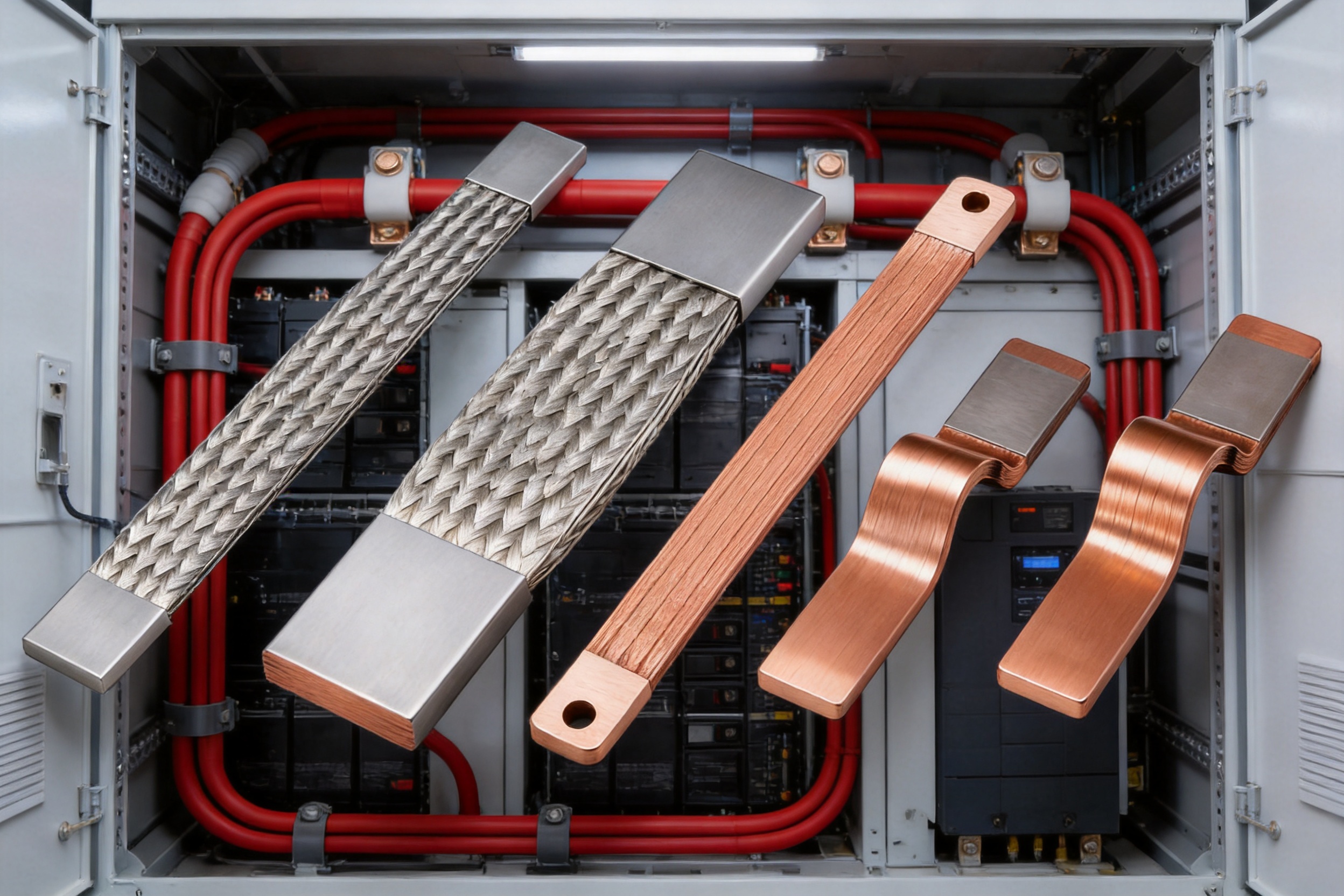
The competitive value of the 2 m and 3 m insulated flexible copper busbar comes from the combination of features rather than from one specification alone. High-purity copper provides a low-resistance conductive path. Laminated construction provides flexibility. Extruded insulation provides integrated protection. Long lengths reduce intermediate joints. Multiple cross-sections allow selection for different current levels and spaces.
Compared with rigid busbars, the product can reduce routing constraints and installation work. Compared with round cables, it can provide a compact flat connection with fewer parallel conductors in selected applications. Compared with short bolted links, it can reduce the number of intermediate joints and simplify assembly.
The company’s manufacturing strengths further improve competitiveness. Engineering support, precision processing, polymer diffusion welding, laser technology, controlled insulation extrusion, and quality-management systems help produce components suitable for demanding OEM and new-energy applications. Customers can obtain both standard products and customized solutions from a manufacturer experienced in conductive components.
Another advantage is application breadth. The same product family can support switchgear, distribution panels, energy storage, photovoltaic inverters, wind-power equipment, railway systems, data centers, charging infrastructure, transformers, generators, and industrial machinery. This broad applicability helps system integrators standardize connection concepts across multiple equipment platforms.
11. Frequently Asked Questions
11.1 What current can the insulated flexible busbar carry?
The product family is intended for applications from approximately 125 A to 4,500 A. The actual allowable current depends on conductor dimensions, copper thickness, insulation, ambient temperature, installation method, enclosure ventilation, duty cycle, and allowable temperature rise. A final rating should be confirmed through engineering calculation or testing.
11.2 Are both 2 m and 3 m lengths available?
Yes. The listed range includes 2 m and 3 m insulated flexible busbars. Not every cross-section is available in both lengths, so the required dimension and quantity should be confirmed with the supplier.
11.3 What is the conductor material?
The conductor is based on annealed electrolytic copper, commonly specified as T2 copper. Copper content is generally at least 99.9%, with high-purity options identified up to 99.95%. Tinned copper versions are also available for selected 3 m configurations.
11.4 Can the busbar be bent into a small radius?
Yes. The flexible laminated construction is designed to support compact bends, folds, and twists. The minimum bend radius depends on the selected width, thickness, number of layers, and bending direction. The manufacturer’s recommended bending limits should be followed to avoid conductor or insulation damage.
11.5 What insulation materials are available?
PVC and TPE are identified as available insulation materials. PVC is suitable for many general industrial and power-distribution applications, while TPE can provide greater temperature range and flexibility. The exact material should be selected according to temperature, flame, chemical, vibration, and environmental requirements.
11.6 Is the insulation flame-retardant?
The reference specification identifies the insulation as self-extinguishing and UL94 V-0 rated. The applicable certification and test report should be confirmed for the exact insulation material and product configuration required for the project.
11.7 Can the product be customized?
Yes. Customization can include length, width, conductor thickness, insulation material, insulation thickness, color, terminal geometry, hole positions, exposed conductor sections, bend locations, and special shapes. Customers should provide drawings or interface requirements for engineering review.
11.8 Is a flexible busbar suitable for battery systems?
It can be suitable for battery modules, battery cabinets, energy-storage systems, and related power connections when the electrical, thermal, mechanical, and insulation requirements are satisfied. Battery applications should also consider vibration, thermal cycling, short-circuit forces, terminal design, and service safety.
11.9 What is the difference between red copper and tinned copper?
Red copper generally refers to bare high-conductivity copper as the conductor material, while tinned copper has a protective tin coating over the copper surface. Tinning can improve surface protection and compatibility with some terminals, but the most suitable option depends on temperature, corrosion exposure, joining method, and electrical requirements.
11.10 How should the busbar be installed?
The busbar should be routed without exceeding the recommended bend radius, supported at suitable intervals, protected from sharp edges, and terminated with clean, properly prepared contact surfaces. Fasteners should be tightened to the specified torque, and the completed assembly should undergo insulation, continuity, and mechanical checks before energization.
11.11 Can the product replace a rigid busbar in every application?
No. Flexible busbars are advantageous in compact, misaligned, or vibration-prone connections, but rigid bars may be better for long unsupported runs, structural busbar systems, or applications requiring specific short-circuit bracing. Product selection should be based on the complete electrical and mechanical design.
11.12 What information is needed for a quotation?
Useful quotation information includes required length, conductor width and thickness, current rating, voltage, insulation material, insulation color, terminal dimensions, bend locations, installation environment, operating temperature, quantity, packaging requirements, and applicable testing or certification standards.
12. Conclusion
The 2 m and 3 m red copper insulated soft busbar is a practical high-current connection solution for modern electrical and new-energy systems. Its high-conductivity copper conductor supports efficient power transfer, while the laminated structure allows compact bending, folding, and twisting. Integrated PVC or TPE insulation provides electrical separation, flame-retardant performance, and protection against accidental contact.
Long continuous lengths can reduce splicing, simplify routing, and lower installation effort. Multiple cross-sections and optional tinned copper designs allow the product to serve a broad range of applications, from switchgear and industrial distribution to energy storage, charging equipment, data centers, inverters, rail systems, and battery connection assemblies.
The product’s advantages are strengthened by Zhejiang Zhongyan New Energy Co., Ltd.’s experience in copper foil soft connections, battery conductive components, precision joining, polymer diffusion welding, laser processing, insulation extrusion, and customized OEM manufacturing. Through material control, advanced production equipment, engineering support, and quality-management practices, the company can provide both standard products and application-specific solutions.
For the best result, customers should treat the busbar as part of a complete electrical and mechanical system. Current rating, voltage, temperature, short-circuit forces, insulation coordination, bend radius, support spacing, terminal design, and environmental conditions must all be reviewed. With the correct specification and installation method, the insulated flexible copper busbar can deliver a compact, reliable, and serviceable connection for demanding high-current applications.
References
1. IEC 61439, Low-Voltage Switchgear and Controlgear Assemblies.
2. IEC 60228, Conductors of Insulated Cables.
3. UL 94, Tests for Flammability of Plastic Materials for Parts in Devices and Appliances.
4. ASTM B187, Standard Specification for Copper, Bus Bar, Rod, and Shapes.
5. ASTM B193, Standard Test Method for Resistivity of Electrical Conductor Materials.
6. General engineering practices for high-current copper conductors, flexible laminated busbars, insulation coordination, and thermal design.
7. Manufacturer technical data for 2 m and 3 m insulated flexible red copper busbars, including conductor dimensions, packaging specifications, insulation properties, and listed part configurations.
Product: 2m/3m Red Copper Insulated Soft Busbar

Driven by the development of new energy and aiming for "zero carbon".
Copyright © Zhejiang Zhongyan New Energy Co., Ltd. All Rights Reserved.
