 English
 Español

Custom Composite Laminated Busbars for Rail Transit Power Systems
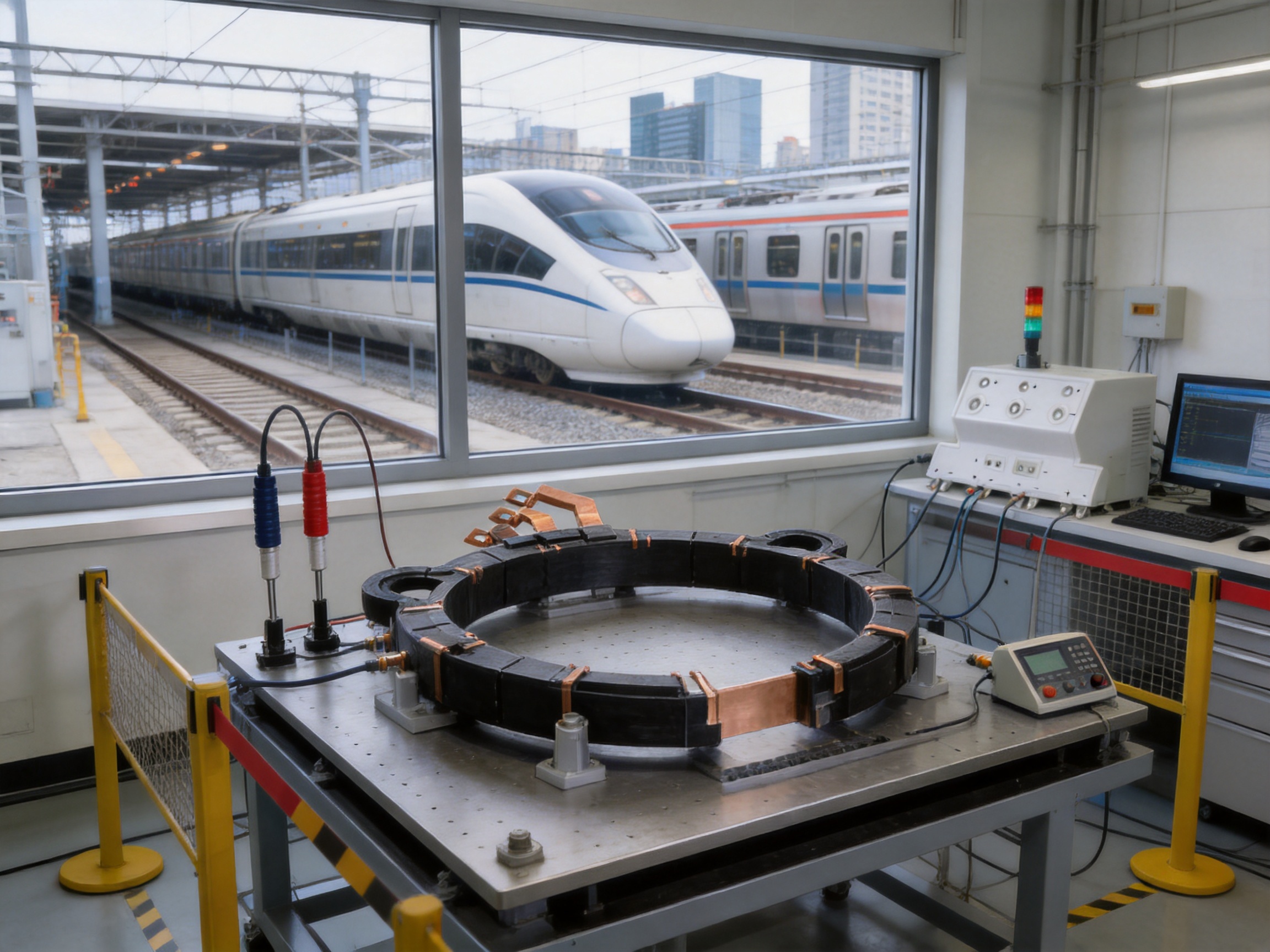
Rail transportation depends on power distribution equipment that can operate safely, consistently, and efficiently under demanding electrical, mechanical, thermal, and environmental conditions. Subway trains, high-speed rail vehicles, traction substations, maintenance systems, and onboard auxiliary equipment all require compact conductors capable of carrying power while withstanding vibration, electrical stress, temperature variation, and restricted installation spaces. Composite laminated busbars provide an advanced solution for these requirements by combining precision-machined conductive layers with carefully selected insulating materials in a controlled multilayer structure.
Custom composite laminated busbars for rail transit power systems are engineered for high-voltage and high-current applications in traction converters, traction transformers, auxiliary power systems, and automatic control systems. Compared with conventional cable assemblies or separated flat conductors, a laminated busbar can offer shorter current paths, lower parasitic inductance, improved voltage distribution, more predictable thermal behavior, and simplified installation. These characteristics are especially important in modern rail vehicles, where switching frequencies are increasing, power density is rising, and available installation space is becoming smaller.
Zhejiang Zhongyan New Energy Co., Ltd. develops and manufactures precision conductive components for power transmission, new energy vehicles, rail transit, communication, and energy storage applications. Its composite laminated busbar capabilities are supported by experienced engineering personnel, specialized production equipment, modern quality management, and practical expertise in high-voltage copper foil soft connections, special-shaped conductors, battery connections, and other electrical connection products.
The company’s approach is based on customized engineering rather than one-size-fits-all production. Each busbar can be designed around the electrical rating, mechanical envelope, insulation system, mounting method, heat dissipation requirement, and service environment of the customer’s rail application. This design flexibility enables the finished component to integrate more effectively with traction equipment and helps reduce the installation compromises associated with standardized conductors.
Custom Composite Laminated Busbars for Rail Transit Power Systems
Content
- 1. The Role of Laminated Busbars in Rail Transportation
- 2. Product Overview and Design Scope
- 3. Representative Technical Configurations
- 4. Low Inductance for Modern Traction Electronics
- 5. Partial Discharge Control and Dielectric Reliability
- 6. Thermal Performance and Heat Resistance
- 7. Electromagnetic Interference Shielding
- 8. Compact Design and Space Utilization
- 9. Installation Accuracy and Reduced Assembly Risk
- 10. Long Service Life in Harsh Rail Environments
- 11. Advanced Manufacturing Process
- 11.1 Engineering Review and Product Definition
- 11.2 Copper Material Preparation
- 11.3 Precision Cutting and Forming
- 11.4 Surface Treatment and Tin Plating
- 11.5 Insulation Layer Preparation
- 11.6 Layer Alignment and Composite Lamination
- 11.7 Welding and Terminal Integration
- 11.8 Finishing, Cleaning, and Marking
- 11.9 Final Inspection and Electrical Testing
- 12. Manufacturing Strengths and Technical Capabilities
- 13. Advantages Compared with Conventional Busbar and Cable Solutions
- 14. Applications in Rail Transit Power Systems
- 15. Design Customization for Original Equipment Manufacturers
- 16. Quality Management and Validation Approach
- 17. Cost Efficiency Beyond the Purchase Price
- 18. Why Choose a Specialized Conductive Component Manufacturer
- 19. Recommended Customer Development Process
- 20. Sustainability and New Energy Development
- 21. Frequently Asked Questions
- Q1: What is a composite laminated busbar?
- Q2: Why are laminated busbars suitable for rail transit?
- Q3: Can the busbar be customized for a specific traction converter?
- Q4: What voltage and current levels can be supported?
- Q5: What does low inductance mean in practical terms?
- Q6: How is partial discharge controlled?
- Q7: Is tin plating available?
- Q8: Can flexible copper sections be integrated?
- Q9: What tests are available for the finished product?
- Q10: What is the benefit of working directly with a specialized manufacturer?
- Q11: Are the listed product dimensions standard catalog sizes?
- Q12: How should a customer begin a project?
- 22. Conclusion
- References
- Product: Custom Composite Laminated Busbars for Rail Transit Power Systems
1. The Role of Laminated Busbars in Rail Transportation
Rail transit power systems must transmit energy through equipment that is frequently exposed to vibration, acceleration, braking forces, electromagnetic interference, and rapid changes in load. In a subway train, the power system may operate in humid tunnels, dusty depots, and outdoor environments within the same service cycle. High-speed rail equipment must additionally meet demanding requirements for weight reduction, compact packaging, thermal stability, and long service intervals.
Traditional wiring solutions often use multiple cables, separate copper bars, terminal blocks, insulating spacers, and additional fasteners. Although these components can perform adequately in simple installations, they may create a larger electrical loop area and a more complicated assembly. More joints also mean more opportunities for installation errors, loose connections, uneven torque, and maintenance difficulties.
A composite laminated busbar consolidates several electrical and insulating functions into a structured assembly. Conductive copper layers are arranged in a defined geometry and separated by dielectric insulation. The layers may include positive and negative conductors, phase conductors, shielding layers, sensing conductors, or auxiliary circuits, depending on the application. The resulting assembly can be shaped to match the available space inside a traction converter, transformer cabinet, control enclosure, or onboard power module.
Because the conductor layers are positioned close to one another, the magnetic fields produced by opposing current paths can partially cancel. This reduces loop inductance and helps control transient voltage overshoot during fast switching. The close-coupled structure can also improve electromagnetic compatibility by limiting the area through which high-frequency fields are generated and received.
For rail transit, these benefits extend beyond electrical performance. A laminated busbar may reduce the number of separate parts, make the connection layout easier to verify, improve repeatability during assembly, and support more compact equipment designs. In a vehicle where every kilogram and every millimeter matter, the integration achieved by a custom busbar can contribute to overall system optimization.
2. Product Overview and Design Scope
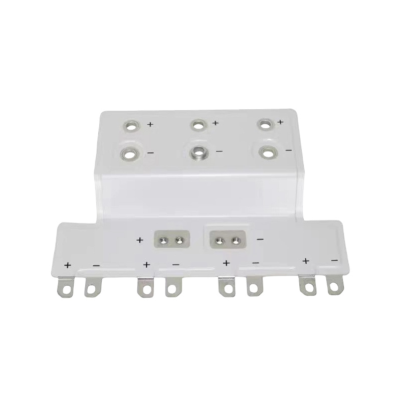
Composite laminated busbars are multilayer power conductors manufactured by combining conductive metal plates or foils with insulating dielectric materials. The conductive layers are typically made from copper, with surface treatments such as tin plating available to improve solderability, contact stability, and resistance to surface oxidation. The insulation system is selected according to the required voltage rating, dielectric strength, partial discharge performance, thermal class, mechanical construction, and production process.
The product can be designed as a straight, stepped, bent, branched, or three-dimensional structure. Holes, slots, terminals, threaded inserts, locating features, and other interfaces may be incorporated according to the customer’s assembly drawings. The busbar can also be designed with clearance zones, creepage paths, edge insulation, and protective barriers to support the required electrical safety margins.
For rail transit applications, the design process normally considers the following parameters:
• Rated voltage and maximum transient voltage
• Continuous current and short-time overload current
• Switching frequency and expected rate of voltage change
• Conductor thickness, width, and current density
• Dielectric strength and partial discharge requirements
• Operating temperature and temperature rise
• Cooling conditions and heat transfer paths
• Vibration, shock, and mechanical retention
• Available installation volume and mounting orientation
• Terminal geometry and connection method
• Required surface treatment and corrosion protection
• Inspection, traceability, and delivery documentation
A significant advantage of custom production is that these factors can be evaluated together rather than separately. A conductor that is electrically adequate may not fit the equipment enclosure. An insulation system with sufficient dielectric strength may not provide the desired thermal performance. A mechanically simple design may have an unnecessarily large current loop. Integrated engineering helps balance these competing requirements.
3. Representative Technical Configurations
The supplied product information includes several representative rail transit busbar configurations. These examples demonstrate the range of dimensions and electrical requirements that can be addressed through custom design. Actual ratings depend on the final geometry, insulation structure, cooling conditions, installation environment, and customer validation requirements.
| Representative Configuration | Conductor Details | Electrical Requirements | Insulation and Test Information |
|---|---|---|---|
| Configuration A | 550 mm × 120 mm; 1.0 mm copper plate; tin-plated surface | 1500 V DC; representative current specification provided as 0 A | Partial discharge: AC 2.6 kV, less than 10 pC |
| Configuration B | 880 mm × 350 mm; 1.5 mm copper plate; tin-plated surface | 2.5 kV DC; 300 A | Dielectric strength: 5 kV DC for 60 seconds, leakage below 2 mA; partial discharge: AC 2.8 kV, less than 10 pC |
| Configuration C | 680 mm × 300 mm; 1.0 mm copper plate; tin-plated surface | 1500 V DC; 50 A | Dielectric strength: 5 kV DC for 60 seconds, leakage below 2 mA; partial discharge: AC 2.8 kV, less than 10 pC |
The first configuration illustrates a compact, high-voltage laminated structure with a 1.0 mm tin-plated copper layer and partial discharge performance specified at AC 2.6 kV. The listed current value is 0 A in the supplied data and should therefore be confirmed with the project engineering team before use as a design rating. This example demonstrates why every electrical specification must be reviewed against the customer’s application and final validation plan.
The second configuration is a larger 880 mm by 350 mm assembly using 1.5 mm copper plate and a 2.5 kV DC voltage requirement. Its representative current rating is 300 A, with a 5 kV DC dielectric withstand test for 60 seconds and leakage below 2 mA. The stated partial discharge result is less than 10 pC at AC 2.8 kV. This type of construction is suitable for applications where a broad conductor area and substantial current capacity are required within a defined equipment envelope.
The third configuration uses a 1.0 mm tin-plated copper plate, measures 680 mm by 300 mm, and is specified for 1500 V DC and 50 A. It includes the same representative dielectric withstand criterion of 5 kV DC for 60 seconds with leakage below 2 mA and partial discharge below 10 pC at AC 2.8 kV. It demonstrates how the same general product family can be adapted for a different balance of size, voltage, current, and insulation performance.
These examples should not be interpreted as a fixed catalog limitation. The manufacturing process can support customized dimensions, conductor arrangements, terminal forms, mounting features, insulation structures, and surface treatments. The final technical drawing and test plan should define the approved production configuration.
4. Low Inductance for Modern Traction Electronics
Low inductance is one of the most important performance advantages of a laminated busbar in a traction power system. When current changes rapidly, the inductance of the connection generates an opposing voltage according to the rate of current change. In power electronic equipment, particularly systems using high-speed semiconductor switching, excessive stray inductance can contribute to voltage overshoot, ringing, electromagnetic emissions, additional semiconductor stress, and increased losses.
A conventional cable arrangement may position conductors several centimeters apart or route them through different paths. This increases the effective current loop area and can result in greater parasitic inductance. A laminated busbar places associated conductors in a controlled, closely coupled geometry. The positive and negative paths, or phase and return paths, can be arranged to reduce the magnetic field around the connection.
Lower inductance supports cleaner switching behavior and can help equipment designers manage the electrical stress placed on power modules, capacitors, and semiconductor devices. It may also reduce the need for additional snubber components or excessive voltage margins, although the complete system must always be evaluated through simulation and testing.
For traction converters, this performance is valuable because the converter may be required to control large amounts of energy while maintaining stable operation during acceleration, regenerative braking, changes in line voltage, and auxiliary load variation. A well-designed laminated busbar creates a more predictable electrical interface between the switching devices and the DC link or output connection.
Low inductance does not result solely from selecting a thicker copper plate. It depends on conductor arrangement, dielectric thickness, overlap area, terminal placement, bend geometry, current direction, and connection to adjacent components. This is why custom design and three-dimensional engineering review are important. The busbar must be optimized as part of the equipment circuit, not considered only as an isolated metal component.
5. Partial Discharge Control and Dielectric Reliability
High-voltage rail equipment requires reliable insulation over a long operating life. Partial discharge is a localized electrical discharge that can occur in voids, interfaces, sharp edges, contaminated areas, or regions of excessive electric field concentration. Repeated partial discharge can gradually damage insulation and reduce the long-term reliability of the assembly.
Composite laminated busbars are designed to control the conditions that contribute to partial discharge. These conditions include air gaps, uneven dielectric interfaces, contamination, insufficient creepage distance, sharp conductor edges, and poorly controlled pressure during lamination. A carefully manufactured structure can reduce internal defects and maintain a more uniform insulation system.
The representative product data specifies partial discharge below 10 pC at AC 2.6 kV or AC 2.8 kV for selected configurations. These values indicate a strong focus on high-voltage insulation quality. The exact test voltage, acceptance criterion, measurement circuit, and test procedure should be confirmed in the project specification because different railway customers and equipment standards may use different test conditions.
Dielectric withstand testing provides another important verification method. Selected configurations are specified for 5 kV DC for 60 seconds with leakage below 2 mA. This test helps confirm that the insulation can withstand a defined overvoltage for a specified duration without breakdown or unacceptable leakage.
Partial discharge testing and dielectric withstand testing serve different purposes. A withstand test verifies resistance to a high applied voltage during a controlled test interval. A partial discharge test provides information about localized discharge activity below the breakdown level. Using both types of evaluation offers a more complete view of insulation performance.
Manufacturing controls are essential to achieving repeatable results. Material cleanliness, layer alignment, pressure control, temperature control, edge finishing, curing conditions, and inspection of the finished assembly can all influence dielectric performance. A supplier with experience in high-voltage connection products is better positioned to identify and control these variables during product development and mass production.
6. Thermal Performance and Heat Resistance
Current-carrying conductors generate heat according to their electrical resistance and load profile. In a compact rail vehicle enclosure, heat may be difficult to remove because air circulation is limited and multiple heat-producing components are installed close together. Excessive temperature can accelerate insulation aging, increase resistance, affect terminal reliability, and reduce the service life of nearby components.
A composite laminated busbar can be designed to support efficient heat distribution through the copper layers and through selected mounting interfaces. Conductor thickness, width, overlap, surface area, and terminal geometry all influence thermal behavior. The dielectric system must also retain its mechanical and electrical properties at the expected operating temperature.
The product design process can include current-density analysis, thermal simulation, temperature-rise testing, and evaluation of the busbar within the customer’s actual enclosure. These methods help identify hot spots near terminals, bends, narrow sections, bolt holes, and transitions between different conductor widths.
Compared with a collection of smaller cables, a flat laminated conductor may distribute current across a broader cross-sectional area and provide a more orderly heat path. It may also reduce the need for multiple cable lugs and overlapping terminals, which can be sources of localized resistance and heat generation.
Thermal performance must be considered together with electrical insulation. Increasing the copper thickness may improve current capacity but can affect flexibility, weight, bend radius, and lamination stress. Increasing the dielectric thickness may improve voltage margin but reduce heat transfer and increase the overall dimensions. Custom engineering allows these trade-offs to be balanced according to the real operating profile of the rail system.
7. Electromagnetic Interference Shielding
Rail transit vehicles contain traction inverters, control electronics, sensors, communication systems, passenger information equipment, braking controls, and monitoring devices. These systems operate in close proximity, so electromagnetic compatibility is a major consideration. High-frequency switching currents can generate conducted and radiated interference if the current path is not properly controlled.
The laminated busbar structure can contribute to electromagnetic interference management by keeping related current paths close together and reducing loop area. Additional shielding or dedicated conductive layers may be incorporated where required by the circuit design. The effectiveness of the final arrangement depends on grounding, enclosure design, cable routing, switching behavior, filtering, and the complete vehicle architecture.
Compared with widely separated conductors, a closely coupled laminated structure offers a more controlled electromagnetic environment. It can reduce unpredictable coupling paths and support more consistent test results during electromagnetic compatibility evaluation. This is particularly useful in traction converters, where rapid switching edges may create significant high-frequency energy.
The busbar should therefore be designed in coordination with the power module, capacitor bank, grounding system, and equipment enclosure. A supplier that can review the mechanical and electrical interfaces together can help avoid late-stage changes caused by interference problems or unsuitable terminal placement.
8. Compact Design and Space Utilization
Space inside rail vehicles is expensive. Electrical equipment is often installed under the floor, on the roof, or within tightly packed cabinets. Maintenance access must be preserved while meeting requirements for insulation distances, cooling, vibration resistance, and protection against accidental contact.
Custom laminated busbars make it possible to use the available space more efficiently. The conductor can follow a defined two-dimensional or three-dimensional route around capacitors, power modules, cooling structures, and mounting frames. Integrated holes and terminals can reduce the need for separate brackets, cable supports, and intermediate connection pieces.
A compact busbar can also help reduce the total assembly envelope. Shorter connection paths may lower material usage and eliminate unnecessary cable bends. A cleaner layout can make inspection easier because the current path and terminal sequence are visually clear.
Space savings should not be evaluated only by comparing the dimensions of the copper component. The complete installation should be considered, including cable bend radii, terminal blocks, fasteners, insulation sleeves, support brackets, and service clearances. In many cases, the main benefit of a laminated busbar is the reduced system volume created by combining several functions into one engineered assembly.
For rail equipment manufacturers, this may create opportunities to reduce cabinet size, increase power density, or reserve more space for cooling and maintenance. A smaller assembly may also support vehicle weight reduction, although the actual result depends on the full equipment design and material selection.
9. Installation Accuracy and Reduced Assembly Risk
Rail power systems are often assembled in production environments where repeatability and traceability are essential. A connection that depends on manually routing several cables can be more difficult to verify than a predefined laminated component with fixed terminal locations and clear orientation features.
Custom busbars can include locating holes, marked reference points, keyed profiles, integrated insulation, and standardized terminal interfaces. These features help reduce the possibility of reversed polarity, incorrect phase order, improper routing, or interference with neighboring parts. They also support more consistent tightening and inspection procedures.
Reduced installation complexity may lower labor costs and shorten assembly time. It can also reduce the number of individual parts that must be stored, picked, installed, and inspected. Fewer separate components generally mean fewer opportunities for missing hardware, incorrect cable length, damaged insulation, or improper bend radius.
Error prevention is particularly important in high-voltage equipment. A small wiring mistake may not be immediately visible during a basic continuity check but could lead to insulation stress, incorrect switching behavior, or serious equipment damage during commissioning. A purpose-designed laminated busbar provides a more controlled connection architecture.
Installation benefits depend on the engineering quality of the interface. The finished design should clearly define hole tolerances, terminal orientation, tightening requirements, insulation clearances, and permissible assembly forces. Documentation and sample approval are important parts of a reliable supply program.
10. Long Service Life in Harsh Rail Environments
Railway equipment must operate for many years with limited opportunities for replacement. The busbar must therefore withstand not only electrical load but also mechanical and environmental stress. Vibration and shock can affect fasteners, terminals, laminations, and interfaces. Humidity and contaminants can influence insulation resistance and surface corrosion. Repeated thermal cycling can create expansion and contraction between copper, insulation, and mounting structures.
Durability begins with material selection. Copper provides high electrical conductivity and good formability, while tin plating can improve surface protection and contact behavior. The insulating material must be selected for its dielectric strength, thermal performance, adhesion, mechanical stability, and compatibility with the intended manufacturing process.
Edge quality is also important. Burrs, sharp corners, and irregular cut edges can damage insulation or concentrate electric fields. Controlled punching, laser processing, milling, deburring, and inspection can help create a more reliable interface between the conductor and dielectric layers.
The mechanical design should avoid unnecessary stress concentrations. Mounting holes require suitable clearances, and bends must respect the material’s forming limits. Terminals should be positioned so that external cable forces do not overload the laminated structure. Where the application requires it, additional support points or flexible connection sections may be incorporated.
Long-term reliability is best demonstrated through a combination of design review, production inspection, electrical testing, thermal evaluation, and application-level qualification. A supplier with experience in copper foil soft connections and precision conductive components can apply relevant knowledge to conductor flexibility, welding, surface treatment, and high-current interfaces.
11. Advanced Manufacturing Process
11.1 Engineering Review and Product Definition
Manufacturing begins with a detailed review of the customer’s electrical schematic, mechanical drawing, installation environment, and qualification requirements. Engineers evaluate the current paths, conductor polarity, phase arrangement, insulation distances, terminal interfaces, mounting constraints, and heat dissipation conditions.
At this stage, unclear or conflicting specifications should be identified before tooling begins. Questions may include whether the current rating is continuous or intermittent, whether voltage values are nominal or maximum, whether the busbar operates in a sealed enclosure, and whether partial discharge testing applies to the complete assembly or a defined section.
The output of the engineering review is a controlled product definition that may include a two-dimensional drawing, three-dimensional model, layer stack-up, material list, inspection plan, and test specification. Design changes should be documented so that prototypes and production parts remain traceable to an approved revision.
11.2 Copper Material Preparation
Copper plate or foil is prepared according to the required thickness, width, conductivity, and forming characteristics. The representative products use 1.0 mm or 1.5 mm copper plate, with tin-plated surfaces specified for the illustrated rail transit configurations. Other material options may be considered when a project requires a different balance of conductivity, strength, flexibility, or surface performance.
Material identification and incoming inspection help confirm thickness, surface condition, dimensional consistency, and suitability for the planned process. Clean handling is important because oils, particles, and oxidation can affect plating, bonding, welding, or insulation adhesion.
11.3 Precision Cutting and Forming
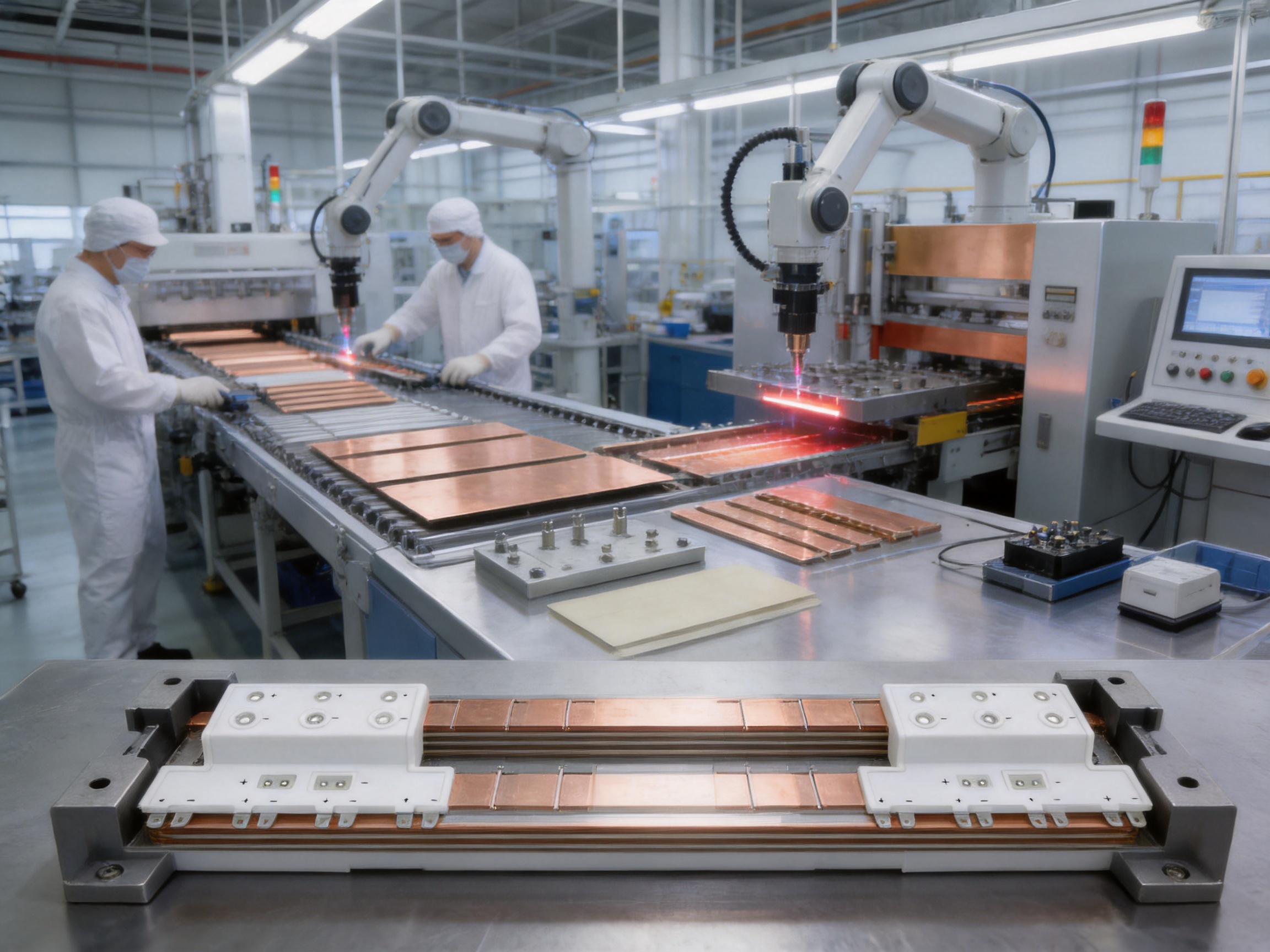
Conductive layers are cut and formed to match the approved geometry. Depending on the shape and production volume, the process may use precision stamping, laser cutting, CNC machining, bending, or a combination of methods. Holes, slots, steps, terminal extensions, and special contours can be produced as part of the conductor preparation process.
Special attention is given to dimensional tolerances and edge condition. The conductor must fit accurately within the insulation structure without damaging adjacent layers. Forming operations are controlled to prevent cracks, distortion, excessive springback, or local thinning that could affect electrical and mechanical performance.
Complex rail busbars may contain several layers with different profiles. The production team must maintain correct orientation and identification throughout the process. Layer marking, fixtures, templates, and controlled work instructions can help prevent assembly errors.
11.4 Surface Treatment and Tin Plating
Tin plating is specified for the representative copper plates in the supplied product information. A tin-plated surface may provide improved resistance to oxidation and support reliable electrical contact. It can also improve solderability where soldered interfaces are part of the customer’s assembly process.
Surface preparation normally includes cleaning and activation before plating. Plating thickness, coverage, adhesion, and appearance should be controlled according to the agreed specification. Areas that require welding, bonding, or special contact performance may require dedicated process instructions.
Good surface treatment depends on both the plating line and pre-treatment quality. Contamination, insufficient cleaning, uneven current distribution, and poor handling can reduce coating consistency. Appropriate inspection and process records help ensure that the supplied parts meet the intended contact and corrosion requirements.
11.5 Insulation Layer Preparation
The dielectric layers are cut and prepared to create the required separation between conductive elements. The insulation design must account for voltage, creepage, clearance, edge coverage, temperature, mechanical stress, and potential environmental exposure.
Insulation layers may include openings for terminals, controlled windows for grounding or mounting, and extended edge regions for additional protection. The shape must prevent unwanted conductor exposure and maintain the required electrical distances after forming and assembly.
Material storage and handling are important because moisture, contamination, and improper temperature can influence dielectric performance. Controlled conditions help preserve the material’s intended characteristics before lamination.
11.6 Layer Alignment and Composite Lamination
Conductive and insulating layers are assembled in a defined sequence using positioning fixtures and process controls. Accurate alignment ensures that terminals, holes, clearances, and active conductor areas correspond to the approved design.
The layers are then laminated under controlled pressure and temperature. The objective is to create a stable composite structure with consistent bonding, minimal voids, and reliable insulation interfaces. Pressure and temperature profiles must be matched to the selected insulation system and assembly thickness.
Improper lamination can lead to wrinkles, delamination, trapped air, uneven thickness, or internal defects. These issues may compromise partial discharge performance or reduce mechanical durability. Process monitoring and sample inspection help maintain stable production conditions.
For high-voltage rail applications, the lamination process is particularly important because internal defects may not be visible from the outside. A mature manufacturing system therefore combines preventive controls with electrical testing and, where appropriate, cross-sectional or other verification methods during development.
11.7 Welding and Terminal Integration
Some busbar designs require welded terminals, copper foil connections, flexible sections, threaded interfaces, or additional conductive attachments. The company’s experience with polymer diffusion welding and laser technology provides a foundation for producing low-resistance, high-reliability conductive joints in precision new energy components.
Welding parameters must be controlled according to the material combination, thickness, joint design, and required mechanical strength. Excessive heat can damage insulation or distort the conductor, while insufficient energy can produce a weak or high-resistance connection. Joint inspection may include visual examination, dimensional checks, resistance measurement, and destructive qualification of process samples.
Where flexible copper foil sections are incorporated, the transition between rigid and flexible areas must be engineered carefully. The design should control current distribution and avoid sharp mechanical stress at the connection boundary. This is valuable for rail equipment that experiences vibration or differential movement between mounted components.
11.8 Finishing, Cleaning, and Marking
After lamination and terminal integration, the busbar may undergo trimming, edge finishing, cleaning, protective treatment, and final dimensional correction. Excess material must be removed without damaging the insulation or exposing conductive layers in prohibited areas.
Product identification may include part number, revision, date code, batch code, polarity marking, or customer-specific traceability information. Clear marking supports installation, inspection, maintenance, and future quality investigation.
11.9 Final Inspection and Electrical Testing
Final inspection may include dimensional verification, hole position checks, conductor thickness confirmation, surface inspection, terminal alignment, insulation appearance, and cleanliness assessment. Electrical checks may include continuity, resistance, insulation resistance, dielectric withstand, and partial discharge testing according to the agreed quality plan.
For representative configurations, the supplied data identifies dielectric withstand testing at 5 kV DC for 60 seconds with leakage below 2 mA and partial discharge limits below 10 pC at specified AC test voltages. These criteria demonstrate the intended focus on high-voltage reliability, but the exact acceptance values for a new project should be confirmed before production.
Test records should be linked to the product batch or serial number wherever required. This provides evidence of conformity and supports the customer’s incoming inspection and railway qualification documentation.
12. Manufacturing Strengths and Technical Capabilities
The company is a high-tech enterprise focused on new energy conductive components and precision electrical connection solutions. Its product scope includes high-voltage electrical copper foil soft connections, special-shaped soft connections, battery soft connections, composite laminated busbars, and related conductive components.
One important strength is the combination of material, processing, and application knowledge. A busbar is not simply a piece of copper; it is a controlled electrical, mechanical, thermal, and insulation assembly. Experience across soft connections, battery interfaces, and high-voltage components allows the engineering team to evaluate how different materials and joining methods behave in practical systems.
The company brings together experienced engineers and technical personnel with capabilities covering product design, research and development, manufacturing, testing, and solution development. This supports faster communication between the customer’s design department and the production team, especially when a product requires multiple prototype revisions.
Advanced professional equipment supports precision processing and repeatable production. Modern production and quality management systems are used to improve stability and consistency. For customized rail components, this is important because the production process must maintain the approved geometry and electrical performance across repeated batches rather than only produce a successful prototype.
The company was established in 2022 and has developed independently based on new energy precision component requirements. Its use of polymer diffusion welding and laser technology patents supports the development of products with ultra-low internal resistance and high reliability. These capabilities are relevant to rail transit busbars where low-loss current transfer, controlled joints, and compact construction are important.
The company has supplied core components to leading enterprises including BYD, CATL, and Jaguar. This experience indicates exposure to demanding new energy supply-chain requirements, although every rail transit project must still be qualified according to its own customer specifications and applicable railway standards.
13. Advantages Compared with Conventional Busbar and Cable Solutions
13.1 Reduced Electrical Loop Area
Closely arranged conductive layers can reduce the loop area compared with separated cable routes. This helps reduce stray inductance and supports cleaner switching performance in converter and inverter applications.
13.2 Integrated Insulation
Instead of installing separate insulation sleeves, spacers, and barriers around multiple conductors, the laminated structure integrates insulation into the component. This can improve organization and reduce the possibility of missing or incorrectly installed protective parts.
13.3 Fewer Connection Points
A custom assembly can replace several cables, lugs, links, and intermediate joints. Fewer connection points may reduce contact resistance variation and simplify inspection, provided that the remaining terminals are correctly engineered and tightened.
13.4 Better Use of Restricted Space
Three-dimensional shaping and integrated mounting features allow the busbar to match the equipment enclosure. This can provide more efficient use of cabinet volume than standard straight conductors.
13.5 Improved Installation Repeatability
Fixed geometry and defined interfaces help make assembly more repeatable. Operators do not need to manually determine cable routing or create multiple bends within a confined area.
13.6 Potential Weight and Labor Savings
The complete system may use fewer support parts and shorter conductive paths. These changes can reduce assembly labor and, depending on the final design, lower total installed weight.
13.7 Controlled High-Voltage Insulation
When manufactured with proper material and process controls, a laminated structure can provide a consistent dielectric system with defined partial discharge and dielectric withstand requirements.
14. Applications in Rail Transit Power Systems
14.1 Traction Converters
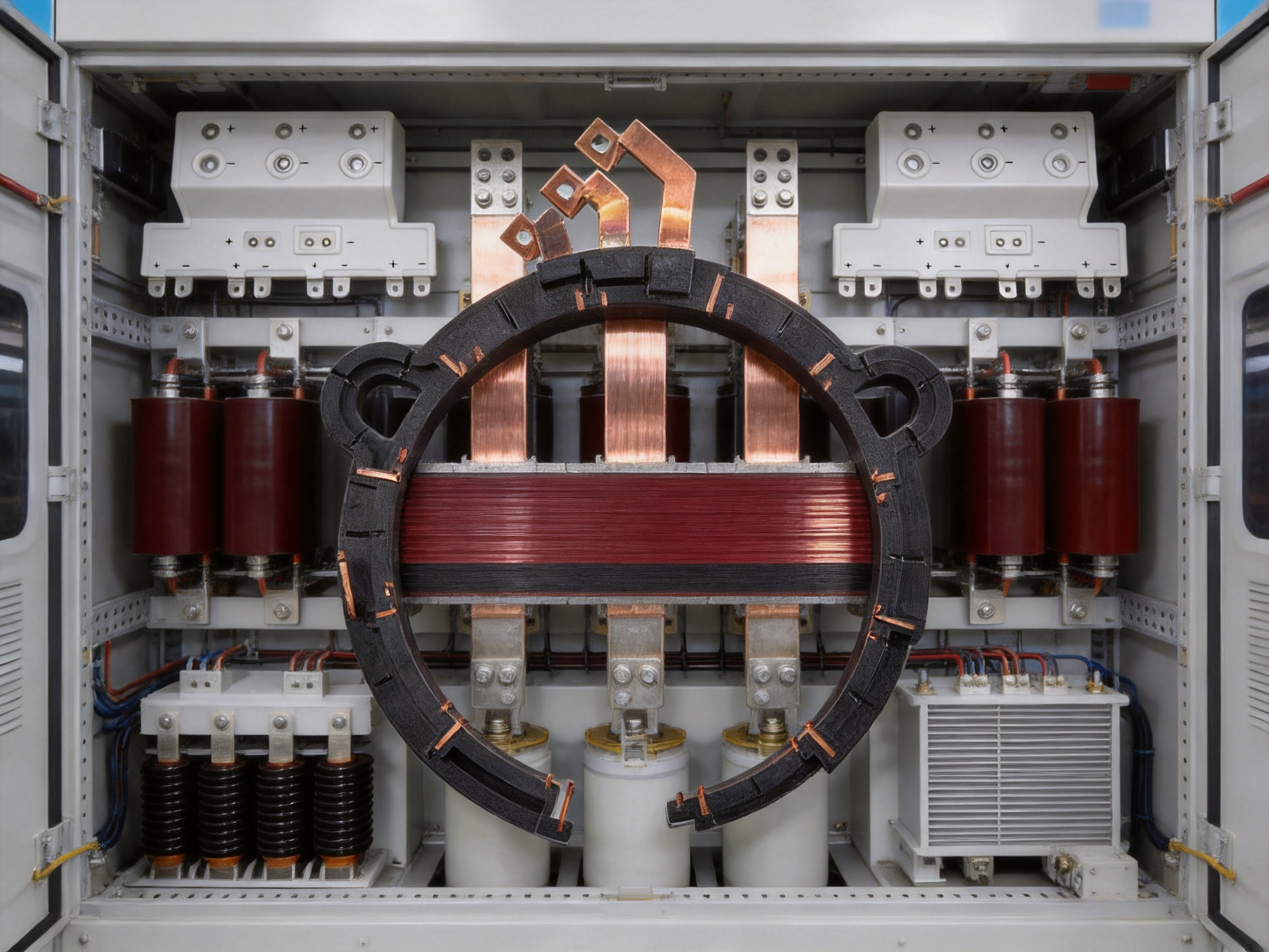
Traction converters transform and control electrical energy supplied to the vehicle’s traction motors. They contain high-power switching devices and DC-link components that can benefit from low-inductance, compact interconnection. Laminated busbars can connect semiconductor modules, capacitors, input terminals, and output phases while controlling the physical relationship between current paths.
The busbar layout can be adapted to the converter’s cooling structure and enclosure. It may include openings for module interfaces, terminal pads for capacitors, and mounting points designed to maintain clearances under vibration.
14.2 Traction Transformers and Associated Equipment
Traction transformers and related high-voltage equipment require reliable connections with controlled insulation. Custom laminated components can be used in selected power distribution sections, converter interfaces, and auxiliary assemblies where a flat, insulated, compact conductor is advantageous.
14.3 Auxiliary Power Systems
Auxiliary converters supply lighting, ventilation, control systems, communication equipment, doors, battery chargers, and other onboard loads. These systems may have lower current requirements than the main traction circuit but still require dependable insulation and compact installation. A product family that supports different voltage and current levels can simplify sourcing across multiple vehicle subsystems.
14.4 Automatic Control and Monitoring Systems
Automatic systems often operate close to high-power switching equipment. Carefully arranged conductive paths can help reduce electromagnetic coupling and make power and control interfaces more orderly. The busbar itself must be coordinated with signal wiring, grounding, shielding, and enclosure design.
14.5 High-Speed Rail and Subway Vehicles
High-speed rail vehicles emphasize weight, reliability, and high power density. Subway systems emphasize compact packaging, frequent acceleration and braking cycles, and long service operation in challenging environments. The same core laminated busbar technology can be adapted to these different requirements by changing layer arrangement, conductor thickness, insulation, terminal structure, and mechanical reinforcement.
15. Design Customization for Original Equipment Manufacturers
Original equipment manufacturers often require components that fit a proprietary enclosure or power module. A standard busbar may be electrically acceptable but mechanically unsuitable. Custom manufacturing enables the conductor to be developed around the equipment rather than forcing the equipment to accommodate a generic part.
Customization may include:
• Overall length, width, and thickness
• Number and order of conductive layers
• Copper thickness and conductor width
• Tin-plated or alternative surface treatment
• Terminal hole position and size
• Threaded inserts and mounting features
• Bent or stepped sections
• Flexible copper foil transitions
• Clearance and creepage structures
• Partial discharge control features
• Protective edge insulation
• Customer-specific labels and packaging
Effective customization requires the exchange of complete information. The customer should provide the electrical schematic, current waveform or load profile where available, voltage class, installation drawing, mating components, environmental conditions, vibration requirements, cooling information, and qualification expectations.
In return, the manufacturer can provide design feedback on conductor width, terminal locations, insulation margins, forming limits, joining methods, and manufacturability. Early cooperation reduces the risk of discovering an interference, thermal, or dielectric problem after tooling and pilot production.
16. Quality Management and Validation Approach
Rail transit components require a disciplined quality approach because reliability is connected to passenger safety, vehicle availability, maintenance cost, and operator reputation. A robust production program should control the entire process from raw material receipt to shipment.
Incoming material inspection verifies that copper, insulation, plating materials, adhesives, and auxiliary parts meet the approved specifications. Process inspection monitors cutting, forming, plating, layer alignment, lamination, welding, and finishing. Final inspection confirms that the completed busbar meets drawing and test requirements.
Prototype validation should evaluate more than basic dimensions. Depending on the project, it may include resistance measurement, thermal testing, dielectric withstand, insulation resistance, partial discharge, vibration, shock, thermal cycling, humidity exposure, and mechanical retention. The selection of tests should be agreed with the customer based on the final application and applicable standards.
Design verification and process validation are related but different. Design verification asks whether the product meets its intended electrical and mechanical requirements. Process validation asks whether the manufacturing method can repeatedly produce conforming products. Both are necessary for a stable rail supply program.
Traceability is valuable when a product includes multiple material lots, plating stages, welding operations, and electrical tests. Controlled records can support root-cause analysis, corrective action, and continuous improvement. Consistent documentation also helps OEM customers prepare their own technical files and approval packages.
17. Cost Efficiency Beyond the Purchase Price
The economic value of a laminated busbar should be evaluated across the total installed cost rather than only the component quotation. A product that is slightly more expensive than a basic copper bar may still reduce total cost by lowering assembly labor, shortening wiring time, reducing support hardware, and improving installation repeatability.
Compact integration can also reduce the size of adjacent enclosures or create space for other equipment. Fewer joints may reduce inspection time and maintenance requirements. More predictable electrical behavior may reduce the need for additional corrective components in a high-frequency converter design.
Long service life is another part of cost efficiency. Railway operators incur significant costs when vehicles are removed from service for troubleshooting or component replacement. A reliable insulated connection can help reduce unplanned downtime, although system availability ultimately depends on the full vehicle design and maintenance program.
Engineering efficiency also influences cost. Early design support can prevent repeated tooling changes and reduce the number of prototype iterations. A supplier that combines development, manufacturing, testing, and quality control can simplify communication and reduce coordination effort across several subcontractors.
18. Why Choose a Specialized Conductive Component Manufacturer
A specialized manufacturer understands that electrical connection products require more than metal fabrication. The supplier must control conductivity, resistance, insulation, mechanical strength, thermal behavior, surface quality, and process repeatability at the same time.
Experience with copper foil soft connections is especially useful for applications requiring flexible transitions or vibration tolerance. Experience with battery soft connections provides knowledge of low-resistance joining, compact current paths, and high-volume precision manufacturing. Experience with composite laminated busbars adds the ability to manage multilayer insulation and high-voltage testing.
The company’s broader focus on new energy conductive components supports a practical understanding of electrified transportation and energy storage systems. Its development of a complete research and development innovation system covering materials science, precision machining, testing, and verification allows different technical disciplines to contribute to product improvement.
This integrated capability is valuable for OEM customers that need more than a drawing-to-part service. The manufacturer can participate in design-for-manufacturing reviews, prototype development, process optimization, and qualification planning. The result is a closer connection between the customer’s system requirements and the finished electrical component.
19. Recommended Customer Development Process
Step 1: Define the Application
Provide information about the rail vehicle, traction or auxiliary circuit, operating voltage, continuous and peak current, switching characteristics, ambient temperature, cooling conditions, vibration, and installation location.
Step 2: Review the Mechanical Interface
Share the enclosure drawing, mating components, mounting points, terminal positions, service clearances, and any restrictions on weight, bend radius, or assembly direction.
Step 3: Select Materials and Layer Structure
Evaluate copper thickness, surface treatment, insulation type, dielectric thickness, shielding requirements, flexible sections, and joining methods. The layer stack-up should be reviewed for both electrical and thermal behavior.
Step 4: Complete Engineering Analysis
Use electrical calculations, inductance analysis, thermal evaluation, mechanical review, and manufacturability assessment to refine the design. Where necessary, use prototypes or samples to confirm critical assumptions.
Step 5: Produce and Test Samples
Prototype samples should be checked for dimensions, fit, resistance, insulation performance, dielectric withstand, and partial discharge where applicable. Customer assembly trials can identify interface issues before production release.
Step 6: Approve the Production Process
After the design is accepted, confirm the bill of materials, process instructions, inspection plan, packaging method, traceability requirements, and change-control procedure.
Step 7: Monitor Ongoing Supply
Production batches should be controlled through incoming inspection, process monitoring, final testing, and documented corrective action. Any material, tooling, or process change should be reviewed according to the customer’s approval requirements.
20. Sustainability and New Energy Development
Electrified transportation is an important part of global efforts to reduce dependence on fossil fuels and improve energy efficiency. Reliable conductive components support the development of electric vehicles, rail systems, renewable energy equipment, and energy storage infrastructure.
Efficient busbar design can reduce unnecessary conductor length, optimize material usage, and support higher power density. A durable component can also reduce replacement frequency and the resource consumption associated with maintenance. These benefits depend on responsible material selection, manufacturing efficiency, product longevity, and appropriate end-of-life handling.
Zhejiang Zhongyan New Energy is investing in key energy-storage technologies and expanding its capabilities in battery cells and connection systems. Its long-term direction includes integrated design of battery cells and connection systems, high-performance customized battery solutions, and continued development of new energy precision components.
This broader technology strategy complements the company’s rail transit busbar business. Both fields require low-resistance electrical paths, compact packaging, reliable insulation, controlled joining, and consistent manufacturing. Knowledge developed in one application area can support innovation in another while maintaining the specific qualification requirements of each industry.
21. Frequently Asked Questions
Q1: What is a composite laminated busbar?
A composite laminated busbar is a multilayer electrical conductor made by arranging copper or other conductive layers with insulating dielectric materials. The layers are bonded or laminated into a compact assembly with defined terminals, mounting features, and electrical clearances.
Q2: Why are laminated busbars suitable for rail transit?
They provide compact, organized, and repeatable power connections. Their closely coupled conductors can reduce inductance, while integrated insulation supports high-voltage applications. Custom geometry also helps the busbar fit restricted spaces in traction converters, transformers, and auxiliary power equipment.
Q3: Can the busbar be customized for a specific traction converter?
Yes. Dimensions, copper thickness, layer arrangement, terminal locations, mounting holes, insulation structure, surface treatment, and flexible sections can be customized according to the equipment design and electrical requirements.
Q4: What voltage and current levels can be supported?
The supplied representative configurations include 1500 V DC, 2.5 kV DC, 50 A, and 300 A examples. The actual voltage and current capability must be confirmed through electrical, thermal, dielectric, and mechanical evaluation of the specific design.
Q5: What does low inductance mean in practical terms?
Low inductance means that the connection generates less opposing voltage when current changes rapidly. In a traction converter, this can help reduce switching overshoot, ringing, electromagnetic emissions, and stress on power semiconductor devices.
Q6: How is partial discharge controlled?
Partial discharge is controlled through suitable insulation materials, accurate layer alignment, proper edge treatment, controlled lamination, reduction of voids and air gaps, appropriate creepage and clearance distances, and electrical testing. Representative products specify less than 10 pC at designated AC test voltages.
Q7: Is tin plating available?
Yes. The representative rail transit configurations use tin-plated copper plates. Tin plating can improve surface protection and contact performance. The required plating thickness and coverage should be defined in the project specification.
Q8: Can flexible copper sections be integrated?
Depending on the design, flexible copper foil or soft connection sections may be integrated into the assembly. This can help accommodate vibration, differential movement, or installation constraints. The transition between rigid and flexible areas must be engineered and tested carefully.
Q9: What tests are available for the finished product?
Possible tests include dimensional inspection, continuity, resistance, insulation resistance, dielectric withstand, partial discharge, thermal performance, mechanical retention, vibration, shock, and environmental testing. The exact test plan should be agreed according to the application and customer standards.
Q10: What is the benefit of working directly with a specialized manufacturer?
Direct cooperation can shorten communication paths and allow electrical, mechanical, material, joining, and production issues to be reviewed together. This supports faster customization, improved manufacturability, stable quality, and more efficient prototype development.
Q11: Are the listed product dimensions standard catalog sizes?
The listed dimensions are representative examples provided for rail transit applications. They should not be treated as a complete catalog. Custom dimensions and structures can be developed based on approved technical drawings.
Q12: How should a customer begin a project?
The customer should provide the electrical specifications, mechanical interface drawings, operating environment, qualification requirements, expected annual quantity, and desired delivery schedule. The engineering team can then review feasibility and propose a suitable layer structure and manufacturing route.
22. Conclusion
Custom composite laminated busbars provide a practical and technically advanced method for distributing power in rail transit systems. By combining precision copper conductors with controlled insulation layers, they support low-inductance circuit design, high-voltage dielectric reliability, partial discharge control, thermal management, electromagnetic compatibility, compact packaging, and repeatable installation.
The representative configurations demonstrate the ability to address different rail requirements, including 1500 V DC and 2.5 kV DC systems, copper plates from 1.0 mm to 1.5 mm, current examples up to 300 A, dielectric withstand testing at 5 kV DC for 60 seconds, and partial discharge results below 10 pC under specified conditions. Final ratings must always be confirmed through application-specific engineering and validation.
The strongest value of a custom busbar comes from the combination of product design and manufacturing control. Precision cutting, forming, tin plating, insulation preparation, layer alignment, composite lamination, welding, finishing, and electrical testing must work together to produce a reliable component. Zhejiang Zhongyan New Energy Co., Ltd. supports this process with engineering experience, specialized equipment, new energy conductive component expertise, and capabilities in materials, precision processing, testing, and verification.
For rail transit equipment manufacturers, traction system integrators, and power electronics developers, a well-designed laminated busbar can reduce connection complexity and create a more compact, dependable, and serviceable power architecture. Through early engineering collaboration and controlled production, the technology can be adapted to the electrical, mechanical, thermal, and environmental demands of modern subway and high-speed rail systems.
References
1. IEC 60243-1, Electrical Strength of Insulating Materials—Test Methods, Part 1: Tests at Power Frequencies.
2. IEC 60664-1, Insulation Coordination for Equipment Within Low-Voltage Systems—Principles, Requirements and Tests.
3. IEC 61373, Railway Applications—Rolling Stock Equipment—Shock and Vibration Tests.
4. IEC 62477-1, Safety Requirements for Power Electronic Converter Systems and Equipment.
5. EN 50124-1, Railway Applications—Insulation Coordination—Part 1: Basic Requirements—Clearances and Creepage Distances.
6. EN 50155, Railway Applications—Rolling Stock—Electronic Equipment.
7. EN 45545-2, Railway Applications—Fire Protection on Railway Vehicles—Part 2: Requirements for Fire Behavior of Materials and Components.
8. IPC-2221, Generic Standard on Printed Board Design Principles, referenced for general insulation spacing and electrical design concepts where applicable.
9. Manufacturer technical information for custom composite laminated busbars used in rail transit power systems.
10. Manufacturer process and quality information for copper foil soft connections, precision conductive components, and new energy electrical connection systems.
Product: Custom Composite Laminated Busbars for Rail Transit Power Systems

Driven by the development of new energy and aiming for "zero carbon".
Copyright © Zhejiang Zhongyan New Energy Co., Ltd. All Rights Reserved.
