 English
 Español

Power Quality Composite Laminated Busbars for Reliable High-Current Distribution
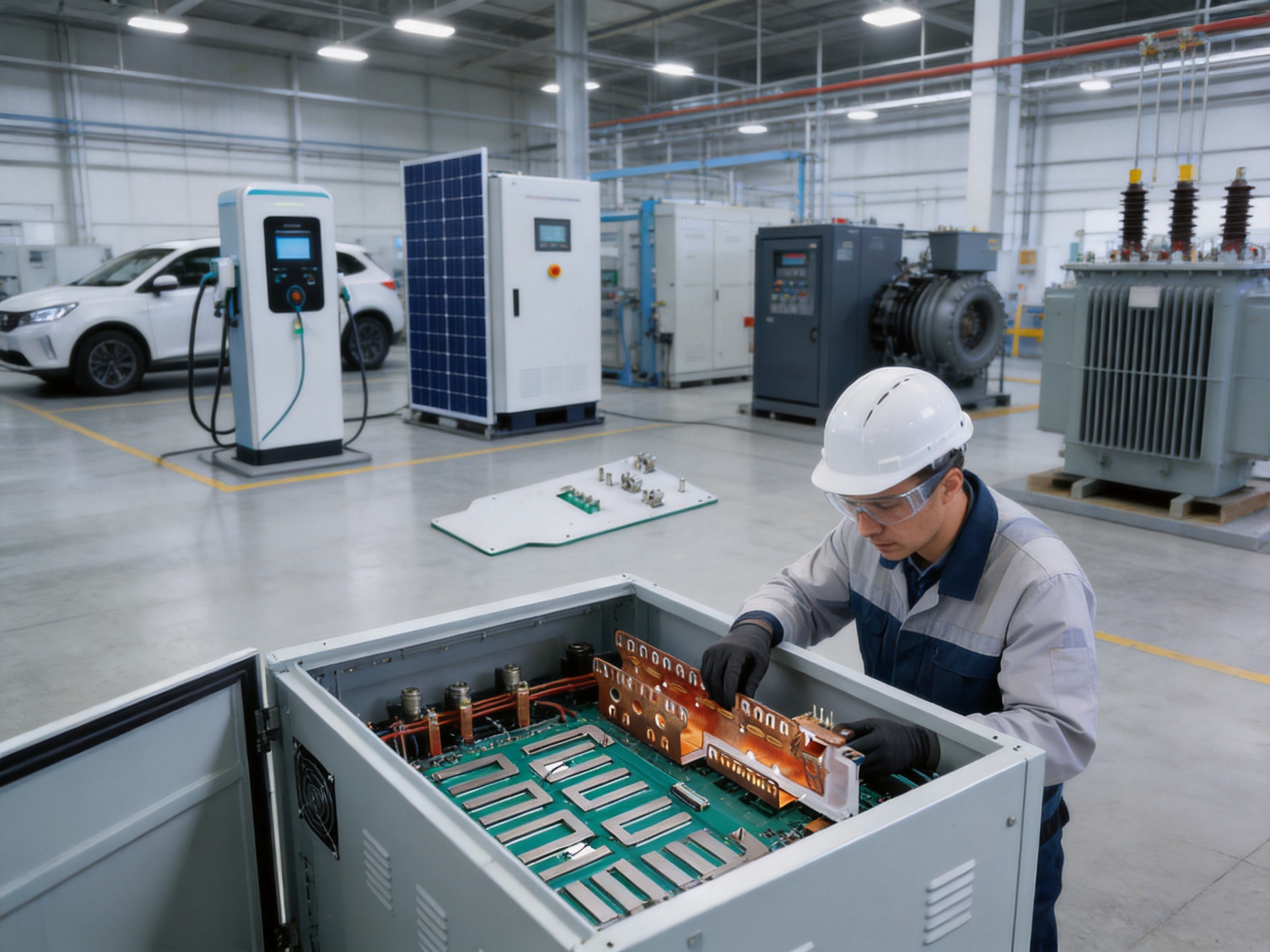
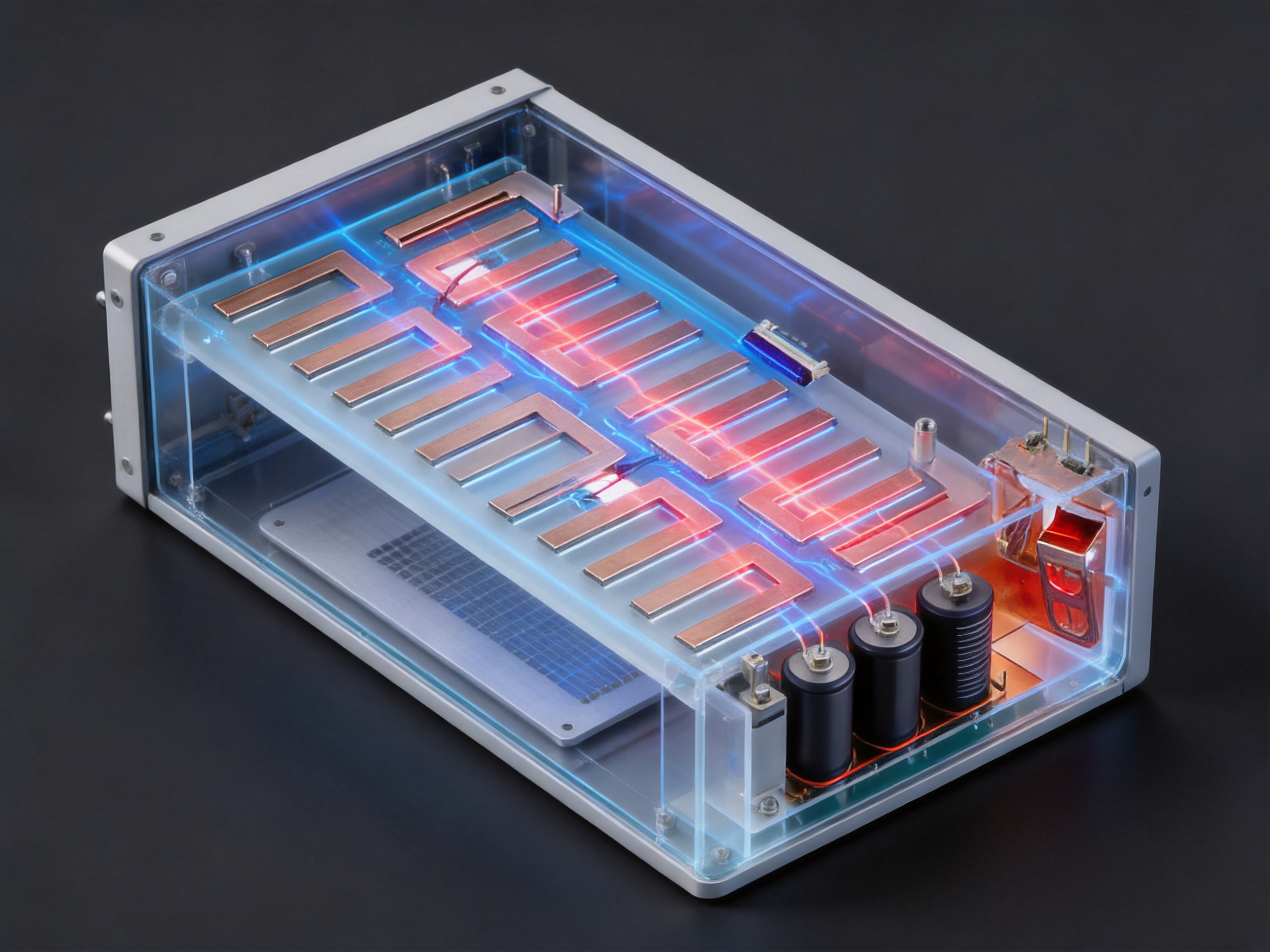
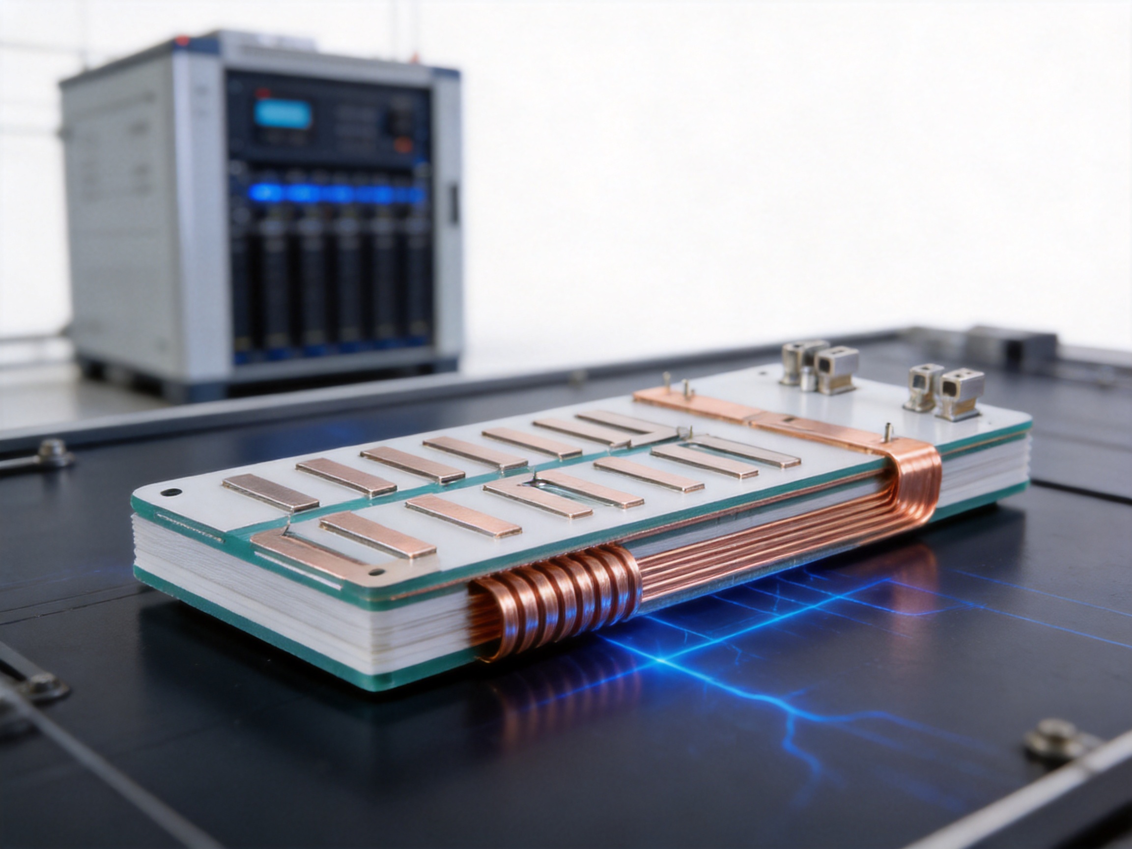
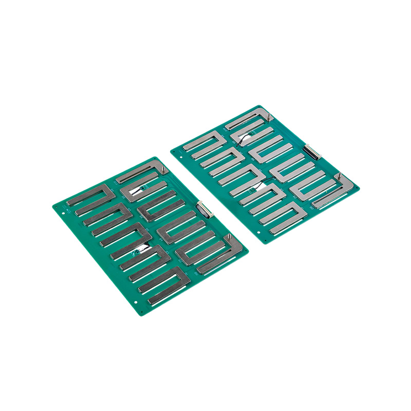
Power Quality Composite Laminated Busbar
Modern power converters, battery systems, renewable-energy installations, industrial drives, and medium- and low-voltage distribution equipment increasingly require electrical connections that combine high current capacity with controlled electrical performance. A busbar is no longer simply a thick metal strip used to carry current from one point to another. In advanced power systems, the busbar is part of the electrical circuit, the thermal-management system, the insulation structure, and the mechanical assembly. Its geometry, material, joint design, insulation arrangement, and manufacturing accuracy can all influence system reliability.
Power Quality Composite Laminated Busbar is designed for applications in which conventional rigid copper busbars may create unnecessary inductance, difficult assembly conditions, mechanical stress, and inconsistent connection performance. By combining precisely formed conductive layers with insulating materials and carefully controlled manufacturing processes, a laminated busbar can provide a compact, low-inductance, thermally efficient, and installation-friendly current path.
The product concept is particularly valuable for power electronics and new-energy equipment. Inverters, converters, battery energy-storage systems, charging equipment, industrial power supplies, and motor drives often experience fast switching transients. If the positive and negative conductors are physically separated by large distances, the resulting loop inductance can increase voltage overshoot and electromagnetic interference. A properly designed laminated busbar places the current paths close together, reducing the area of the electrical loop and helping the system manage high-frequency switching behavior.
In addition to electrical performance, the product addresses practical limitations found in traditional rigid busbar joints. Rigid connections can be difficult to install when equipment tolerances, thermal expansion, vibration, or alignment errors are present. Excessive mechanical stress may be transferred to transformer bushings, power semiconductor terminals, cable lugs, or enclosure supports. A composite laminated structure, combined with flexible or expansion-joint elements where required, can improve assembly tolerance and reduce stress concentration.
Zhejiang Zhongyan New Energy Co., Ltd. manufactures conductive components and precision connection systems for power transmission and distribution, electric vehicles, rail transit, communications, and energy storage. Its capabilities include copper foil soft connections, special-shaped flexible connections, battery soft connections, and other customized electrical components. The company’s experience in precision manufacturing and new-energy connection technology supports the development of laminated busbars for demanding power-quality applications.
Content
- Understanding the Role of a Laminated Busbar
- Product Configuration and Available Electrical Ratings
- How Laminated Construction Improves Power Quality
- Thermal Performance and Current-Carrying Capability
- Mechanical Flexibility and Expansion-Joint Technology
- Insulation, Dielectric Strength, and Safety
- Manufacturing Process and Quality Control
- Advantages Over Conventional Rigid Busbars
- Applications in New-Energy and Industrial Equipment
- Customization and Engineering Support
- Company Manufacturing Strengths
- Recommended Design and Selection Procedure
- Installation and Maintenance Considerations
- Q&A
- What is a composite laminated busbar?
- How does a laminated busbar improve power quality?
- Can the product replace a conventional rigid copper busbar?
- What current ratings are available?
- What voltage ratings are available?
- Why are the copper surfaces tin-plated?
- What is the purpose of the stacked thin-copper expansion joint?
- Can the busbar be customized?
- What tests are performed on the product?
- Is a laminated busbar suitable for battery energy storage?
- How should the correct busbar rating be selected?
- What information should be provided for a quotation or design review?
- Conclusion
- References
- Product: Power Quality Composite Laminated Busbar
Understanding the Role of a Laminated Busbar
A laminated busbar is a multilayer electrical distribution assembly. It generally consists of two or more conductive layers, insulation layers, protective materials, and connection terminals. The conductive layers may be made from copper or aluminum, depending on the current, weight, conductivity, corrosion, and cost requirements of the application. Copper is commonly selected where high conductivity, compact dimensions, and stable connection performance are priorities.
Unlike a simple uninsulated bar, a laminated busbar is engineered as a complete electrical interface. Its design may include positive and negative conductors, phase conductors, signal or sensing paths, insulation barriers, mounting holes, terminal pads, bends, and connection features. The finished assembly can be customized to fit the internal geometry of an inverter, battery pack, switchgear cabinet, charging module, or energy-storage container.
The close arrangement of the conductors is one of the most important features of the design. When forward and return current paths are positioned near one another, their magnetic fields partially cancel. This reduces loop inductance compared with widely spaced cables or conventional separated busbars. Lower inductance can help reduce switching voltage spikes, improve the operating margin of semiconductor devices, and support cleaner high-frequency current delivery.
A laminated busbar can also reduce wiring complexity. Several individual cables, rigid bars, insulating spacers, and support brackets may be replaced by one integrated assembly. This can save internal space and reduce the number of separate parts that must be handled during installation. A defined busbar layout also improves repeatability from one system to another, which is important for standardized production and quality control.
Product Configuration and Available Electrical Ratings
The Power Quality Composite Laminated Busbar is available in customized configurations. The supplied product information includes multiple dimensional and electrical options, allowing the design to be matched to different equipment layouts and current levels. The copper plates or copper foils are tin-plated to support stable contact performance and provide a surface suitable for many connection environments.
| Configuration | Dimensions | Conductor Thickness | Rated Voltage | Rated Current | Dielectric Strength |
|---|---|---|---|---|---|
| Option A | 420 mm × 200 mm | 1.5 mm copper plate | 1000 V DC | 300 A | 5 kV DC for 60 seconds, leakage below 2 mA |
| Option B | 630 mm × 200 mm | 2.0 mm copper plate | 100 V DC | 300 A | 5 kV DC for 60 seconds, leakage below 2 mA |
| Option C | 350 mm × 200 mm | 1.5 mm copper plate | 1000 V DC | 200 A | 5 kV DC for 60 seconds, leakage below 2 mA |
| Option D | 320 mm × 420 mm | 2.0 mm copper plate | 800 V DC | 600 A | 5 kV DC for 60 seconds, leakage below 2 mA |
| Option E | 510 mm × 210 mm | Two layers, 1.5 mm copper foil | 800 V DC | 100 A | 3.5 kV DC for 60 seconds, leakage below 2 mA |
The configurations above illustrate the product’s design range rather than a limitation on customization. Actual ratings should be confirmed for the final application because permissible current depends on conductor thickness, copper area, ambient temperature, installation orientation, cooling conditions, duty cycle, insulation materials, terminal design, and allowable temperature rise.
The listed dielectric-strength values demonstrate the insulation system’s ability to withstand a high-voltage test for a specified duration. The stated leakage-current limits provide an additional indication of insulation integrity during testing. Application engineers should select the appropriate test voltage, creepage distance, clearance, insulation system, and production inspection method according to the relevant equipment and market requirements.
How Laminated Construction Improves Power Quality
Reduced Loop Inductance
In a fast-switching power circuit, every conductor has parasitic inductance. When current changes rapidly, the voltage generated by that inductance can be expressed in simplified form as V = L × di/dt. This means that even a relatively small inductance can create a substantial transient voltage when the current changes in a very short time.
Traditional layouts may use long cables or separated rigid busbars for the positive and negative paths. Such arrangements increase the physical loop area and may increase parasitic inductance. A laminated busbar places the conductors in a controlled, closely coupled structure. The shorter and more compact current loop can reduce the magnitude of voltage overshoot and help protect insulated-gate bipolar transistors, metal-oxide-semiconductor field-effect transistors, silicon carbide modules, and other switching devices.
Lower inductance does not eliminate the need for appropriate semiconductor snubbers, gate-drive design, grounding, shielding, and system-level electromagnetic compatibility measures. However, it provides a stronger foundation for controlling switching behavior. It may also reduce the effort required to manage ringing and transient energy in high-power converter assemblies.
Lower Electromagnetic Interference Potential
Large current loops can radiate magnetic fields and interact with nearby control circuits, sensors, communication wiring, and metal structures. Closely coupled laminated conductors reduce loop area and can help limit radiated electromagnetic energy. This is especially useful in compact equipment where power and control components must be installed close together.
A lower-inductance structure may also reduce high-frequency ringing caused by the interaction of parasitic inductance and capacitance. Cleaner switching waveforms can support more predictable system behavior. Nevertheless, the final electromagnetic performance depends on the complete equipment design, including enclosure construction, grounding, shielding, switching frequency, modulation strategy, cable routing, and filter components.
Improved Voltage Distribution
Composite laminated busbars can be designed with controlled conductor spacing and defined insulation layers. This creates a more predictable electrical geometry than an assembly built from separately routed cables and manually fitted insulating barriers. A controlled layout can reduce accidental proximity between conductors and support consistent clearances throughout the assembly.
For high-voltage direct-current systems, the geometry of the insulation system is particularly important. Sharp edges, uneven surfaces, contamination, mechanical movement, and insufficient creepage distance may increase the risk of partial discharge or surface tracking. Precision forming, edge treatment, insulation placement, and final inspection are therefore essential parts of the product’s value.
Thermal Performance and Current-Carrying Capability
High current produces heat through electrical resistance. A busbar must transfer that heat to the surrounding environment without exceeding the allowable temperature of the conductor, insulation, terminals, or neighboring components. Copper offers high electrical conductivity and supports compact current paths. The final thermal performance, however, depends on much more than the metal itself.
Conductor cross-sectional area, surface condition, contact resistance, joint pressure, airflow, mounting method, ambient temperature, and duty cycle all influence temperature rise. A laminated busbar can be engineered with broad flat conductors that distribute current over a larger area than many small wires. This may improve heat spreading and reduce localized hot spots when the terminal and connection design are properly matched.
The product information includes a configuration rated at up to 600 A, demonstrating suitability for high-current assemblies when the complete system is designed for the required thermal conditions. A 600 A rating should not be interpreted as universal for every enclosure or duty cycle. Engineers should perform thermal validation under representative operating conditions, including continuous current, overload events, switching patterns, ambient temperature, cooling airflow, and neighboring heat sources.
Tin-plated copper surfaces may support consistent electrical contact and help protect the copper from oxidation. Surface plating can also improve solderability or compatibility with selected terminals and fastening methods. The appropriate plating thickness and finish should be verified according to the intended environment, contact system, temperature range, and service life.
Thermal Advantages Compared with Conventional Assemblies
Compared with a collection of smaller wires, a flat copper conductor can offer a more direct thermal path and a more organized internal layout. Compared with a single thick rigid bar, a composite laminated assembly may provide more controlled spacing and greater flexibility in routing. Compared with manually assembled cable harnesses, it can reduce the number of individual connection points that might become loose or generate additional contact resistance.
Thermal performance is also influenced by installation quality. A busbar that is forced into position, misaligned with terminals, or fastened with uneven pressure may experience mechanical stress and localized heating. Customized dimensions and accurately positioned holes help reduce these risks. When the busbar is designed around the equipment enclosure, the assembly can be installed with fewer adjustments and less bending at the final production stage.
Mechanical Flexibility and Expansion-Joint Technology
Traditional rigid busbar joints can be vulnerable to alignment errors, thermal expansion, vibration, and assembly tolerances. When two rigid components are connected without sufficient flexibility, movement may be transferred to equipment terminals or insulating supports. Over time, this stress can contribute to loosening, cracking, deformation, or fatigue at the joint.
The product development concept includes a bendable expansion joint made from stacked thin red-copper sheets. This structure replaces a traditional rigid joint with a flexible current-carrying element. Multiple thin sheets can move slightly relative to one another, allowing the joint to accommodate displacement while maintaining a large conductive cross-section.
Such a flexible joint can be useful at busbar-to-busbar connections, busbar-to-transformer-bushing interfaces, and busbar-to-cable outgoing lines. These points often experience different mechanical conditions. A transformer bushing may have strict allowable loading limits, while a cable connection may move during installation or service. A flexible transition can help decouple these movements from the main rigid conductors.
Flexibility must be engineered carefully. The bend radius, number of layers, copper thickness, connection length, fastening method, and expected movement range all affect service life. Repeated bending beyond the design limit can cause fatigue. The joint should therefore be installed without sharp folds, twisting, excessive tension, or unsupported weight. Proper mechanical support remains important even when a flexible section is included.
Insulation, Dielectric Strength, and Safety
The insulation system is a fundamental part of a laminated busbar. It separates conductive layers, protects personnel and neighboring components, supports voltage withstand, and helps maintain stable electrical performance during the service life of the equipment. Depending on the design, insulation may include dielectric films, bonded layers, molded sections, sleeves, barriers, or additional protective coverings.
The specified product configurations include dielectric-strength tests at 3.5 kV DC or 5 kV DC for 60 seconds, with leakage below 2 mA. These test values provide a basis for quality verification, but the final product must be evaluated according to the voltage level, pollution degree, environmental conditions, and applicable standards of the target equipment.
Insulation design should account for clearance through air and creepage distance along surfaces. Humidity, dust, condensation, salt contamination, chemical exposure, vibration, and temperature cycling can affect insulation performance. Edges and corners should be treated or covered to minimize the possibility of cutting, puncturing, or concentrating electrical stress in the insulating material.
A responsible design process also considers production handling. Insulation can be damaged during drilling, bending, terminal installation, cleaning, or transportation. Electrical testing after assembly helps identify defects that may not be visible during visual inspection. Depending on the application, additional tests may include insulation-resistance measurement, hipot testing, dimensional inspection, continuity testing, torque verification, and thermal evaluation.
Manufacturing Process and Quality Control
The quality of a composite laminated busbar depends on the consistency of every production stage. Copper selection, cutting accuracy, forming, surface treatment, insulation placement, lamination, joining, finishing, and testing must work together. A weakness in one stage can reduce the performance of the entire assembly.
Material Selection and Preparation
Production begins with the selection of suitable copper plate or copper foil. The material must provide the required conductivity, thickness, flexibility, surface quality, and mechanical strength. Copper sheets are inspected for dimensional accuracy, scratches, contamination, oxidation, edge damage, and flatness before processing.
Where tin-plated surfaces are specified, the plating condition must be controlled. Uniform surface coverage supports stable contact behavior and helps protect the conductor from environmental exposure. Preparation may include cleaning, degreasing, surface activation, and inspection before subsequent forming or assembly operations.
Precision Cutting and Forming
Each conductive layer is cut according to the approved drawing. Dimensional precision is important because small deviations can affect hole alignment, terminal contact area, insulation clearance, and installation fit. CNC machining, precision stamping, laser processing, or other suitable methods may be selected according to the material thickness and geometry.
Forming operations create bends, offsets, terminal transitions, and three-dimensional features. Controlled forming reduces the risk of cracks, burrs, deformation, or excessive residual stress. For high-current applications, the formed geometry must preserve the intended cross-sectional area and avoid unnecessary restrictions in the current path.
Insulation Lamination and Layer Registration
During assembly, conductive layers and insulation materials are positioned according to the approved stack-up. Registration accuracy ensures that the intended clearances and overlaps are maintained. The assembly process must prevent wrinkles, trapped contamination, air pockets, and displacement of the insulating layers.
Where bonding or lamination is used, temperature, pressure, time, and material compatibility must be controlled. Excessive process heat may affect insulation or surface treatment, while insufficient pressure may lead to weak bonding or internal voids. Production records support traceability and help identify the cause of any process variation.
Joining and Terminal Processing
Terminals may be formed as part of the copper layer or attached using an appropriate joining method. The joint must provide low electrical resistance and adequate mechanical strength. Depending on the design, processes may include welding, brazing, diffusion joining, riveting, bolting, or other qualified techniques.
Zhejiang Zhongyan New Energy has developed experience with polymer diffusion welding and laser technology for new-energy precision components. These capabilities are relevant to applications requiring low internal resistance, stable joints, and repeatable production. The selected joining process should always be validated for the specific copper thickness, terminal structure, operating current, thermal cycle, and required mechanical strength.
Inspection and Electrical Testing
Final inspection may include dimensional checks, visual examination, surface inspection, insulation verification, dielectric-strength testing, continuity testing, and resistance measurement. For customized products, inspection fixtures can be used to verify hole positions, bend angles, terminal orientation, and overall envelope dimensions.
Testing at the end of production does not replace process control. Quality must be built into the manufacturing sequence through material traceability, equipment maintenance, operator training, controlled work instructions, and documented inspection points. This approach is especially important for products installed in battery systems, power converters, and other equipment where field replacement may be difficult or costly.
Advantages Over Conventional Rigid Busbars
Better Tolerance to Installation Variation
A rigid busbar requires accurate alignment between all connection points. If the enclosure, support brackets, transformer terminals, or cable positions vary slightly, the installer may need to force the busbar into place. This can create unwanted stress and complicate production.
A customized laminated busbar can incorporate bends, offsets, flexible sections, and precisely located connection holes. These features help the component conform to the equipment layout. The result is a more controlled installation process and less dependence on manual adjustment.
More Compact Electrical Packaging
Traditional assemblies may require separate positive and negative busbars with insulation spacers and additional support hardware. A laminated design integrates the layers into one organized component. This can reduce the installation footprint and free space for cooling channels, capacitors, control boards, sensors, or protective devices.
Compact packaging is particularly valuable in electric vehicles, charging modules, battery packs, and industrial converters. Equipment designers can use the available volume more efficiently while maintaining a known conductor arrangement.
Lower Inductance Than Widely Spaced Conductors
Because the forward and return conductors can be placed close together, laminated busbars generally offer lower loop inductance than separated cables or widely spaced rigid bars. This supports high-speed switching applications and may reduce the severity of voltage overshoot and ringing.
The exact inductance value depends on layer spacing, conductor geometry, current distribution, terminal arrangement, and the length of the current path. Therefore, a final design should be evaluated using calculation, simulation, or measurement where switching performance is critical.
Improved Assembly Repeatability
Manual cable routing can vary between production units. Cable length, bend radius, terminal orientation, and clamping force may differ from one assembly to another. A laminated busbar is produced to a defined drawing and can be installed in a prescribed orientation. This supports repeatable electrical and mechanical performance.
Repeatability can also reduce labor time. The installer does not need to measure and route several separate conductors inside the enclosure. A pre-engineered busbar can be mounted using designated holes and connection points, provided that the design and equipment interfaces are properly matched.
Integrated Insulation and Protection
Separate rigid bars require additional insulation barriers, sleeves, spacers, or protective covers. These components may shift during installation or create additional assembly steps. A laminated busbar incorporates insulation into the assembly and provides a more organized approach to electrical separation.
Integrated insulation does not eliminate the need for equipment-level protective measures. The finished assembly must still be protected against accidental contact, abrasion, contamination, moisture, and mechanical damage. However, it can reduce the number of loose insulating parts and simplify the overall design.
Applications in New-Energy and Industrial Equipment
Battery Energy-Storage Systems
Battery energy-storage systems use high-current connections between cells, modules, contactors, fuses, inverters, and power-conversion equipment. A laminated busbar can provide a compact interconnection between the battery rack and power electronics. Its controlled geometry supports insulation coordination and helps manage transient currents during charge and discharge.
Energy-storage applications also require careful consideration of fault currents. The busbar must be selected with suitable continuous-current and short-circuit withstand capabilities. Mechanical supports, protective devices, enclosure design, and thermal monitoring must be integrated into the system-level safety strategy.
Electric Vehicles and Charging Equipment
Electric vehicles and charging equipment have limited internal space and frequently use high switching frequencies. Low-inductance laminated busbars can support compact inverter, onboard charger, DC fast-charger, and battery-distribution designs. Reduced wiring complexity can also help simplify assembly and improve serviceability.
Vehicle applications impose additional requirements, including vibration, thermal cycling, humidity, salt exposure, weight reduction, and long-term fatigue resistance. A product selected for these applications must be validated against the relevant environmental and mechanical conditions.
Solar Inverters and Renewable-Energy Converters
Photovoltaic inverters, wind-power converters, and other renewable-energy systems contain switching devices that transform variable electrical energy into controlled AC or DC power. Laminated busbars can connect capacitors, semiconductor modules, filters, and output terminals while maintaining a compact current path.
These systems may operate continuously for long periods under changing ambient conditions. Thermal design, insulation reliability, and resistance to vibration and humidity are therefore important. Custom dimensions allow the busbar to fit the converter’s internal architecture and cooling arrangement.
Industrial Drives and Power Supplies
Motor drives, welding equipment, UPS systems, industrial rectifiers, and high-power DC supplies can benefit from low-inductance current distribution. The busbar can be designed around semiconductor modules, DC-link capacitors, contactors, and output terminals. Flexible transition sections may reduce stress at points connected to external cables or heavy components.
Transformers and Distribution Equipment
In medium- and low-voltage distribution systems, the quality of busbar joints affects operating reliability. Flexible copper-sheet expansion joints can accommodate movement between rigid sections and reduce the mechanical load on transformer bushings. This is useful where thermal expansion and equipment vibration cannot be ignored.
Customization and Engineering Support
A major advantage of working with a specialized busbar manufacturer is the ability to design the component around the customer’s equipment rather than forcing the equipment to accept a generic part. Customization may include overall length and width, copper thickness, number of conductive layers, insulation material, terminal shape, hole pattern, bend angle, surface treatment, flexible-joint structure, and labeling.
The engineering process normally begins with drawings, three-dimensional models, electrical ratings, installation conditions, and environmental requirements. The manufacturer can review current paths, mounting points, clearance zones, bend locations, and connection interfaces. If the customer does not yet have a complete design, the busbar supplier may help convert system requirements into a manufacturable component.
Important input information includes rated voltage, continuous current, overload current, short-circuit conditions, switching frequency, permissible temperature rise, enclosure dimensions, cooling method, insulation requirements, terminal materials, fastening method, vibration level, and expected service life. Early communication reduces the risk of late-stage interference between the busbar and other equipment.
Prototype production can be used to confirm installation fit and electrical performance before mass production. Prototype testing may include dimensional verification, high-voltage insulation testing, thermal mapping, resistance measurement, vibration evaluation, and installation trials. Design changes should be documented so that the approved version is clearly identified before production begins.
Company Manufacturing Strengths
Zhejiang Zhongyan New Energy Co., Ltd. is a high-tech enterprise focused on new-energy conductive components and precision electrical connection solutions. The company was established in 2022 and has developed capabilities in battery soft connections, high-voltage copper-foil flexible connections, special-shaped soft connections, and related components.
The company brings together experienced engineers and technical teams with expertise in product design, research and development, manufacturing, and solution development. Its production approach emphasizes stable and consistent results through professional equipment, modern quality-management systems, and controlled manufacturing processes.
Its independently developed polymer diffusion welding and laser technologies are intended to support products with low internal resistance and high reliability. These technologies are relevant when a connection must carry high current while remaining compact and mechanically stable. The company also has experience supporting major enterprises in the new-energy sector, including BYD, CATL, and Jaguar, according to the supplied company information.
The company’s broader research direction covers materials science, precision machining, testing, and verification. This multidisciplinary foundation is useful for laminated busbar development because the product combines materials, electrical design, thermal behavior, mechanical structure, insulation, and manufacturing accuracy.
In addition to serving power transmission and distribution, the company supports applications in electric vehicles, rail transit, communications, and energy storage. This application range exposes the engineering team to different requirements for current capacity, flexibility, vibration resistance, dimensional control, and environmental reliability.
Recommended Design and Selection Procedure
Customers should begin by identifying the electrical operating conditions. The rated voltage and current are only the starting points. The design team should also define peak current, overload duration, short-circuit current, switching frequency, current direction, acceptable voltage drop, and allowable temperature rise.
The second step is to establish the mechanical envelope. The busbar’s maximum length, width, height, bend radius, mounting points, terminal locations, and service clearances should be defined. The component must fit without interference with capacitors, cooling plates, insulation barriers, sensors, covers, or moving parts.
The third step is to define the insulation and environmental requirements. These include clearance, creepage distance, dielectric-strength test voltage, insulation resistance, pollution degree, humidity, altitude, temperature range, vibration, shock, chemical exposure, and condensation risk.
The fourth step is to select the conductor and surface treatment. Copper thickness, number of layers, plating, terminal structure, and connection process should be selected according to current density, flexibility, thermal performance, corrosion conditions, and assembly requirements.
The final step is validation. A prototype or first article should be inspected for fit, insulation, resistance, temperature rise, mechanical behavior, and installation quality. If the busbar is used in a high-power switching system, inductance and transient performance should also be evaluated as part of the complete power loop.
Installation and Maintenance Considerations
Before installation, technicians should verify the part number, orientation, insulation condition, terminal cleanliness, and mounting hardware. The busbar should not be forced into alignment. If the connection points do not match, the cause should be investigated rather than corrected by excessive bending or prying.
Fasteners should be tightened according to the specified torque and sequence. Uneven tightening can produce nonuniform contact pressure and increase resistance. Excessive torque may deform the copper or damage insulation, while insufficient torque may allow movement and heating during operation.
Flexible expansion joints should be installed within their intended movement range. They should not support the weight of unrelated components or be used as a substitute for proper mechanical brackets. The bend area should remain free from sharp edges and should not be repeatedly flexed during installation.
Maintenance inspections may include visual examination for discoloration, loose fasteners, insulation damage, corrosion, deformation, and signs of overheating. In high-power systems, periodic thermal imaging can help identify abnormal temperature differences between phases or connection points. Any maintenance procedure must follow the equipment manufacturer’s isolation and safety requirements.
Q&A
What is a composite laminated busbar?
A composite laminated busbar is a multilayer electrical conductor assembly that combines copper or other conductive layers with insulation and connection features. The layers are arranged to provide a compact, controlled, and often low-inductance current path.
How does a laminated busbar improve power quality?
By placing forward and return conductors close together, the busbar can reduce loop inductance and help limit voltage overshoot, ringing, and electromagnetic interference associated with rapid current changes. The final improvement depends on the complete converter and grounding design.
Can the product replace a conventional rigid copper busbar?
It can replace conventional rigid busbars in many applications, provided that the voltage, current, temperature, insulation, mechanical, and short-circuit requirements are properly evaluated. A customized design may include rigid sections, laminated layers, and flexible expansion joints in one assembly.
What current ratings are available?
The supplied configurations include ratings from 100 A to 600 A, with examples using 1.5 mm or 2.0 mm copper conductors. The applicable rating depends on the exact design, cooling conditions, duty cycle, connection method, and allowable temperature rise.
What voltage ratings are available?
The provided examples include 100 V DC, 800 V DC, and 1000 V DC configurations. The final voltage rating must be confirmed according to the insulation system, clearance, creepage, environmental conditions, and applicable equipment requirements.
Why are the copper surfaces tin-plated?
Tin plating can help protect copper surfaces from oxidation and support stable electrical contact. It may also improve compatibility with selected connection methods. The required plating specification should be confirmed for the application environment and service life.
What is the purpose of the stacked thin-copper expansion joint?
The stacked thin-copper expansion joint provides a flexible current path between otherwise rigid sections. It can accommodate limited movement caused by thermal expansion, vibration, installation tolerance, or equipment displacement while reducing mechanical stress on connected terminals.
Can the busbar be customized?
Yes. Dimensions, copper thickness, number of layers, terminal position, hole pattern, bends, insulation, plating, flexible sections, and other features can be developed according to the customer’s equipment and electrical requirements.
What tests are performed on the product?
Depending on the product specification, testing may include dimensional inspection, visual examination, continuity, resistance, insulation resistance, dielectric-strength testing, terminal verification, and thermal validation. The supplied configurations specify dielectric testing at 3.5 kV DC or 5 kV DC for 60 seconds, with leakage below 2 mA.
Is a laminated busbar suitable for battery energy storage?
Yes. Laminated busbars are suitable for many battery energy-storage interconnections, including links between battery modules, contactors, fuses, capacitors, and power converters. The design must account for continuous current, fault current, insulation coordination, temperature, vibration, and service safety.
How should the correct busbar rating be selected?
Selection should consider continuous and peak current, duty cycle, ambient temperature, cooling, conductor cross-section, joint resistance, insulation temperature, short-circuit withstand, voltage, and installation arrangement. A nominal current value alone is not sufficient for final selection.
What information should be provided for a quotation or design review?
Useful information includes electrical schematics, three-dimensional drawings, required dimensions, current and voltage ratings, temperature limits, connection details, insulation requirements, environmental conditions, quantity, testing requirements, and target delivery schedule.
Conclusion
Power Quality Composite Laminated Busbar technology provides a practical solution for modern electrical systems that demand compact packaging, controlled power quality, reliable insulation, and high-current capability. Its closely coupled conductor arrangement can reduce loop inductance and support cleaner switching behavior. Its integrated structure can simplify assembly and improve dimensional repeatability. Its flexible expansion-joint technology can address the mechanical limitations of traditional rigid busbar connections.
The available configurations demonstrate a broad range of dimensions, conductor thicknesses, voltage ratings, current ratings, and dielectric-strength requirements. The product can be adapted for battery systems, energy storage, power converters, renewable-energy equipment, industrial drives, charging systems, transformers, and distribution assemblies.
The product’s performance depends on correct engineering and manufacturing. Precise copper processing, controlled insulation lamination, reliable joining, tin-plated contact surfaces, dimensional inspection, and electrical testing are all necessary to achieve consistent results. Zhejiang Zhongyan New Energy Co., Ltd. combines conductive-component expertise, flexible-connection experience, polymer diffusion welding, laser technology, and new-energy application knowledge to support customized busbar development.
For equipment manufacturers seeking an alternative to widely spaced cables or rigid copper-bar assemblies, a custom laminated busbar can offer a more integrated approach to electrical distribution. When its electrical, thermal, mechanical, and insulation characteristics are validated as part of the complete system, it can contribute to improved reliability, easier installation, and longer service life for advanced power equipment.
References
IEC 60664-1, Insulation Coordination for Equipment Within Low-Voltage Systems: Principles, Requirements and Tests.
IEC 61439 series, Low-Voltage Switchgear and Controlgear Assemblies.
IEC 62477-1, Safety Requirements for Power Electronic Converter Systems and Equipment.
IEEE Std 519, Recommended Practice and Requirements for Harmonic Control in Electric Power Systems.
International Electrotechnical Commission, Electrical Conductors and Busbar System Design Principles.
United States Department of Energy, Power Electronics and Energy-Storage System Engineering Guidance.
Manufacturer-provided technical data for Power Quality Composite Laminated Busbar configurations and electrical test values.
Manufacturer-provided company information concerning conductive-component research, polymer diffusion welding, laser processing, and new-energy connection solutions.
Product: Power Quality Composite Laminated Busbar

Driven by the development of new energy and aiming for "zero carbon".
Copyright © Zhejiang Zhongyan New Energy Co., Ltd. All Rights Reserved.
