 English
 Español

PVC Dipped and Powder-Coated Insulated Busbars: Reliable Power Distribution for Modern Energy Systems
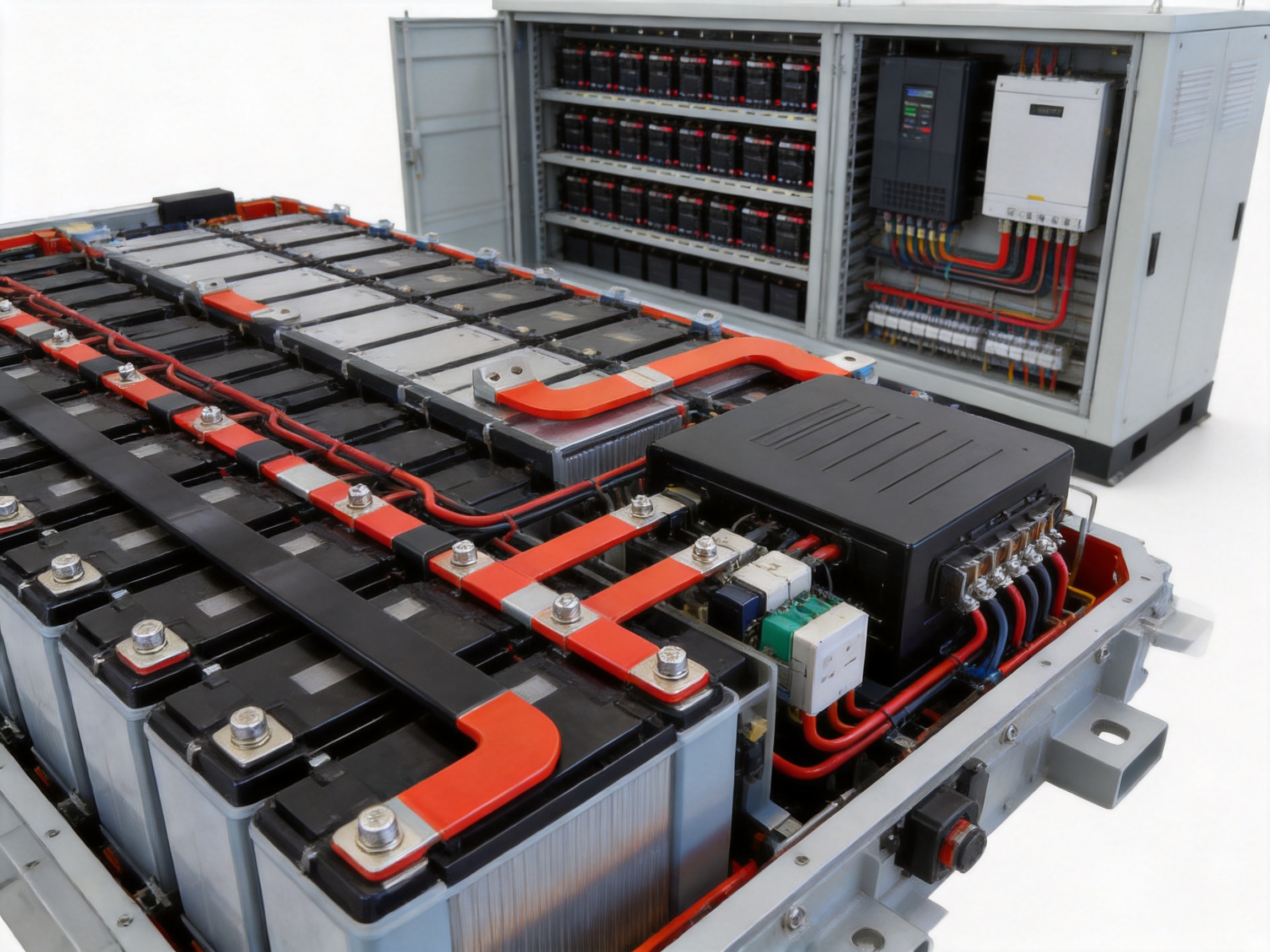
Electrical power systems are becoming more compact, more powerful, and more demanding. New energy vehicles, battery storage systems, industrial drives, switchgear, inverters, and distribution cabinets all require conductive components that can carry high currents safely while occupying limited space. In these applications, the busbar remains one of the most important electrical connection components. However, a bare copper or aluminum busbar is not always sufficient for modern operating environments. Without suitable insulation and surface protection, it may be vulnerable to short circuits, corrosion, mechanical damage, contamination, and accidental contact.
PVC-dipped and powder-coated insulated busbars provide a practical solution to these challenges. By combining the high conductivity of copper or aluminum with a durable insulating layer, these busbars support safer, cleaner, and more reliable electrical designs. They can be manufactured in straight, bent, drilled, tapped, or specially shaped configurations to meet the requirements of specific equipment and installation spaces.
Zhejiang Zhongyan New Energy Co., Ltd. specializes in the development and manufacture of conductive components and customized busbar solutions. Its PVC-dipped and powder-coated busbars are designed for power distribution, electric vehicles, battery packs, energy storage systems, electric motors, industrial equipment, and other high-current applications. The company integrates material selection, precision processing, insulation treatment, inspection, and customized production to provide complete solutions rather than standard raw metal strips alone.
This article explains the construction, performance characteristics, manufacturing technologies, customization capabilities, and application value of insulated copper and aluminum busbars. It also describes how an experienced manufacturer can help equipment designers achieve better electrical safety, space utilization, durability, and production efficiency.
Content
- What Is a PVC-Dipped or Powder-Coated Busbar?
- Core Advantages of Insulated Copper and Aluminum Busbars
- Comparison with Bare Busbars and Conventional Cable Assemblies
- Material Selection: Copper and Aluminum Conductors
- PVC Dipping Technology
- Powder-Coating Technology
- Precision Manufacturing and Customization
- Manufacturing Strengths of a Specialized Supplier
- Application Areas
- Design Considerations for Selecting an Insulated Busbar
- Customization Options
- Why Customized Insulated Busbars Can Improve System Performance
- Installation and Handling Recommendations
- Technical Specifications at a Glance
- Quality Verification and Reliability
- Frequently Asked Questions
- What is the main purpose of coating a copper or aluminum busbar?
- Is PVC dipping better than powder coating?
- Can both copper and aluminum be used?
- Can the busbar be bent into a special shape?
- What insulation thickness is available?
- Can some areas remain uncoated?
- What files are needed for a quotation?
- Are insulated busbars suitable for electric vehicles and battery systems?
- How can a manufacturer support a new project?
- What standards may apply?
- Conclusion
- References
- Product: PVC Dipped & Powder Coated Busbar | Insulated Copper & Aluminum Busbar
What Is a PVC-Dipped or Powder-Coated Busbar?
A busbar is a conductive metal component used to distribute electrical current between circuits, terminals, modules, switches, batteries, or other electrical devices. Compared with multiple cables, a busbar can provide a more compact and organized current path. It may also reduce connection points, simplify assembly, and improve the consistency of electrical resistance across a system.
A PVC-dipped busbar is typically manufactured by applying a plasticized polyvinyl chloride insulating layer over a prepared copper or aluminum conductor. The conductor is first cut, bent, punched, deburred, and cleaned according to the required design. It is then coated through a controlled dipping process that forms a continuous insulating layer around the specified surfaces.
A powder-coated busbar uses an epoxy or other suitable powder coating system. Powder particles are applied to the conductive substrate and then cured under controlled conditions. During curing, the powder forms a continuous protective film with strong adhesion and good resistance to moisture, chemicals, abrasion, and temperature variation.
The conductive core may be produced from high-purity copper, such as T2 or C11000, or from aluminum grades such as 1060 or 1070. The insulation material and process are selected according to the electrical rating, environmental conditions, dimensional requirements, and application of the finished part.
Unlike a simple bare busbar, an insulated busbar combines three functions in one component:
1. It carries electrical current with low resistance.
2. It separates conductive surfaces from neighboring components and grounded structures.
3. It protects the metal substrate against environmental and mechanical influences.
This integrated structure is especially valuable in compact electrical assemblies where clearance is limited and the risk of contact between adjacent conductors is high.
Core Advantages of Insulated Copper and Aluminum Busbars
Improved Electrical Safety
The most important advantage of an insulated busbar is the reduction of accidental electrical contact. A properly applied PVC or epoxy coating creates a barrier between the conductor and surrounding components. This helps reduce the possibility of short circuits, electric shock, arc-related damage, and unintended current paths during installation and operation.
Insulated busbars are particularly useful in high-density power distribution systems. As equipment becomes smaller, conductors are often installed closer together. Traditional air clearance may not provide enough practical protection in every arrangement. A reliable insulation layer adds an additional level of safety without requiring excessive spacing or bulky insulating barriers.
Insulation also helps protect maintenance personnel. Although systems must always be de-energized and handled according to approved safety procedures, insulated surfaces can reduce the risk of accidental contact during assembly, inspection, or service.
High Current-Carrying Capability
Copper and aluminum are widely used because of their favorable electrical conductivity, thermal performance, and manufacturability. T2 and C11000 copper are suitable for applications that require low electrical resistance and high current density. Aluminum grades such as 1060 and 1070 offer a lower material weight and can be useful when overall system mass is an important consideration.
A properly designed busbar can carry substantial current through a compact cross-section. Its broad, flat geometry may also provide an effective heat-dissipation surface. Compared with a collection of smaller wires, a busbar can offer a more direct conductive path and a cleaner layout.
Electrical performance depends on many factors, including cross-sectional area, material grade, length, operating temperature, mounting arrangement, connection quality, and current waveform. For this reason, busbars should be designed according to the actual system requirements rather than selected only by nominal dimensions.
Resistance to Corrosion and Environmental Exposure
Bare metal surfaces may oxidize or corrode when exposed to humidity, dust, oil, salt, chemicals, or other contaminants. Corrosion can increase contact resistance and gradually weaken the reliability of a connection. In severe cases, it may reduce the effective cross-sectional area or cause surface deterioration around terminals and fastening points.
PVC dipping and powder coating provide a protective barrier around the conductor. The coating can help reduce exposure to moisture and corrosive agents while also limiting the accumulation of dust and dirt on the conductive surface. This makes insulated busbars suitable for industrial equipment, outdoor-related power systems, energy storage installations, and other environments where contamination may occur.
The level of protection depends on the selected material, coating thickness, curing quality, exposed areas, and operating environment. Connection surfaces may be intentionally left uncoated or processed separately so that terminals can establish a reliable low-resistance electrical contact.
Mechanical Protection
An insulation layer does more than prevent current leakage. It also protects the metal conductor from scratches, impact, abrasion, and incidental contact with tools or structural parts. This is valuable during transportation, assembly, and maintenance.
Powder-coated surfaces can provide a firm, durable finish that resists normal handling. PVC coatings can provide flexibility and cushioning around selected busbar shapes. When the correct process is used, the finished component can maintain its protective performance during vibration, installation movement, and repeated equipment operation.
Resistance to Temperature Variation
Electrical components may experience significant temperature changes during startup, full-load operation, shutdown, seasonal conditions, or fault events. The material combination must therefore withstand the expected thermal range without cracking, peeling, softening excessively, or losing dielectric performance.
The insulated busbars described in the supplied technical specifications can be configured for a working temperature range of approximately -50°C to 160°C, depending on the selected insulation system, design, and validation requirements. This range supports many demanding industrial and new energy applications, although the final allowable temperature must be confirmed for the exact material formulation and installation conditions.
Efficient Use of Installation Space
A customized busbar can be bent or formed to follow the internal geometry of a cabinet, battery pack, inverter, motor, or power distribution unit. This reduces the need for long cable loops and may help engineers use the available space more efficiently.
Insulation further supports compact design because conductive surfaces can be positioned closer together while maintaining a controlled protective barrier. The result may be a cleaner assembly with fewer separate insulation sheets, sleeves, spacers, and cable supports.
Compactness is particularly important in electric vehicles and energy storage systems. Reducing unnecessary cable length and organizing high-current paths can help lower weight, simplify assembly, and improve the serviceability of the finished product.
Comparison with Bare Busbars and Conventional Cable Assemblies
Bare busbars remain useful in many electrical systems, especially when they are installed inside controlled enclosures with sufficient clearance and additional insulating barriers. However, they require more attention to spacing, protective covers, contamination control, and installation procedures. Any accidental contact between adjacent bare conductors can create a serious fault condition.
Insulated busbars provide a built-in protective layer. This can reduce dependence on separate covers and simplify the layout of high-current conductors. The insulation also provides a visual distinction between circuits when different colors are specified.
Compared with conventional cable assemblies, busbars may provide a more compact and rigid current path. Cables are flexible and convenient for many applications, but they can require more routing space, support points, lugs, bends, and termination operations. A custom busbar can combine the conductor, formed geometry, mounting holes, and insulation into a single engineered component.
The following table summarizes general differences. Actual performance depends on the design, material, and application.
| Item | Bare Busbar | Insulated Busbar | Multi-Cable Assembly |
|---|---|---|---|
| Electrical insulation | Requires external barriers or clearance | Integrated PVC or powder coating | Provided by cable jackets |
| Space utilization | Good, but clearance may be required | Very good for compact layouts | May require routing and bending space |
| Mechanical rigidity | High | High with surface protection | Flexible, depending on cable type |
| Customization | Cutting, bending, punching, and forming | Cutting, bending, punching, forming, and coating | Length, terminals, and harness routing |
| Protection against contamination | Limited without enclosure protection | Improved by the coating layer | Generally provided by the cable jacket |
| Assembly efficiency | Requires careful insulation and mounting | Can reduce separate insulation parts | May involve multiple cables and terminals |
| Typical applications | Switchgear, cabinets, power systems | EVs, ESS, inverters, motors, industrial equipment | Control systems, flexible connections, general wiring |
Insulated busbars do not replace every cable or every bare conductor. Instead, they are most valuable where high current, compact installation, mechanical stability, and electrical protection must be combined in one part.
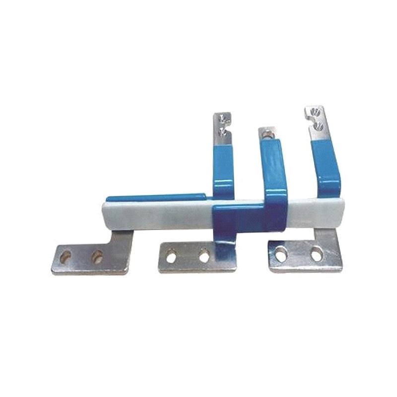
PVC Dipped & Powder Coated Busbar | Insulated Copper & Aluminum Busbar
Material Selection: Copper and Aluminum Conductors
Copper Busbars
Copper is selected for many busbar applications because of its high electrical conductivity, excellent contact performance, and proven reliability. T2 and C11000 copper are common choices for power distribution and high-current applications. Copper busbars can be used in switchgear, distribution cabinets, battery packs, electric motors, inverters, transformers, and industrial equipment.
Copper also offers good thermal conductivity, which helps transfer heat away from the current path. This is important in applications where continuous current produces heat and the busbar is installed in a confined space.
Another benefit is its suitability for precision fabrication. Copper can be laser cut, punched, bent, drilled, tapped, and machined into complex shapes. This allows a manufacturer to produce parts with specific terminal positions, mounting holes, offsets, and connection structures.
Aluminum Busbars
Aluminum provides a useful alternative when low weight, cost control, or large cross-sectional dimensions are important. Grades such as 1060 and 1070 are used in electrical applications because of their suitable conductivity and workability.
An aluminum busbar may be advantageous in transportation and new energy applications where every reduction in mass contributes to system efficiency. Aluminum can also be manufactured into broad or thick conductive sections to support the required current capacity.
Aluminum surfaces require appropriate preparation and connection design because oxide formation can affect contact performance. A professional manufacturing process considers surface cleaning, terminal design, contact treatment, and fastening conditions to produce a stable electrical connection.
Selecting the Appropriate Conductor
The choice between copper and aluminum should be based on electrical, thermal, mechanical, dimensional, and economic requirements. Important design questions include:
What is the continuous and peak current?
What voltage and insulation level are required?
What operating temperature and cooling conditions are present?
Is low mass a priority?
What type of terminal or joining method will be used?
Are there restrictions on available space or bending radius?
Will the busbar be exposed to vibration, humidity, oil, salt, or chemical contaminants?
Will the component be installed in a battery pack, cabinet, motor, inverter, or outdoor system?
By reviewing these factors before production, engineers can choose a conductor that balances current capacity, weight, durability, and manufacturing cost.
PVC Dipping Technology
PVC dipping is a practical method for applying an insulating layer to a copper or aluminum busbar. The process begins with a carefully prepared metal component. Its dimensions, hole locations, bend angles, edges, and surface condition must be controlled before coating. Any sharp burrs or contamination may affect coating uniformity and adhesion.
Surface Preparation
Surface preparation may include deburring, cleaning, degreasing, and other treatments appropriate to the conductor material. A clean and stable surface helps the insulation adhere consistently. For aluminum, special attention may be required because the natural oxide layer can influence coating adhesion and electrical contact performance.
Controlled Dipping
During dipping, the prepared busbar is introduced into the PVC coating system under controlled process conditions. The coating thickness can be adjusted according to the electrical insulation requirement, geometry, and intended use. The process must account for flat surfaces, corners, bends, holes, and transitions between coated and uncoated areas.
Uniformity is important. Excessive coating may interfere with assembly dimensions, while insufficient coverage may reduce dielectric protection. Professional production therefore uses controlled parameters and inspection procedures to maintain consistent coverage across batches.
Drying and Finishing
After coating, the component is processed to stabilize the insulating layer. The finished surface should be visually consistent and free from obvious defects such as bubbles, pinholes, cracks, peeling, or exposed conductive areas where insulation is required.
Terminal surfaces may be masked or finished separately. This ensures that bolts, lugs, clamps, or other connectors can establish the required electrical contact. The exact masking and finishing method depends on the drawing and the assembly design.
PVC dipping is often selected where a resilient insulating jacket, color coding, and practical protection against moisture and handling are required. It can be used for both straight and formed busbars when the component geometry is compatible with the process.
Powder-Coating Technology
Powder coating uses dry coating particles that are applied to the conductive substrate and then cured to form a continuous protective film. Epoxy powder coating is widely considered for electrical insulation because it can provide strong adhesion, good dielectric properties, and resistance to moisture and many industrial contaminants.
Application and Coverage
Before powder application, the busbar must be cleaned and prepared. The coating is applied to the specified surfaces, with attention to edges, corners, bends, and recessed areas. The production team must also control the areas that need to remain conductive, such as terminal faces or connection pads.
The target thickness may be adjusted according to the required insulation performance and assembly tolerance. The supplied specification identifies an insulation thickness range of approximately 0.5 millimeters to 2.0 millimeters for customizable designs. The actual value should be confirmed against the product drawing and applicable test requirements.
Curing and Adhesion
After powder application, the part is heated under controlled conditions so that the powder melts, flows, and cures. Correct curing is essential. Under-cured coating may lack the required mechanical and electrical properties, while excessive heat or unsuitable processing may affect the substrate, dimensions, or coating appearance.
Strong adhesion helps the coating remain attached during vibration, temperature cycling, handling, and service. The final surface should be inspected for consistent coverage, smoothness, edge protection, and absence of visible defects.
Advantages of Powder Coating
Powder coating is suitable for applications that require a durable, uniform, and chemically resistant finish. It can provide an effective barrier against moisture, dust, oil, and corrosion-related exposure. Epoxy coatings can also support demanding industrial applications where a robust surface is required.
Color options may include red, black, blue, gray, yellow, green, and other customer-specified colors. Color coding can help identify positive and negative conductors, phases, circuits, or functional groups during assembly and maintenance.
Precision Manufacturing and Customization
The performance of an insulated busbar depends not only on the metal and coating but also on dimensional accuracy. A busbar may need to fit between battery modules, around structural supports, inside a cabinet, or within the limited space of an inverter or motor assembly. A small error in length, bend angle, hole position, or terminal height may prevent installation or create mechanical stress.
Laser Cutting
Laser cutting can produce accurate profiles, slots, and openings in copper or aluminum sheet and bar materials. It is useful for prototypes, complex shapes, and customized production. Accurate cutting helps maintain the designed current path and ensures that mounting and connection features are positioned correctly.
Punching and Drilling
Punching and drilling are used to create mounting holes, terminal holes, slots, and other connection features. Hole diameter, position, edge distance, and burr control all influence assembly quality. For high-current connections, the contact area and fastening geometry must be carefully designed to reduce resistance and avoid localized heating.
Bending and Forming
Busbars can be bent into stepped, offset, U-shaped, L-shaped, or other three-dimensional configurations. Forming allows the conductor to connect components at different heights or directions while maintaining a compact layout.
Controlled bending is important because excessive deformation can reduce the effective cross-section, create cracks, damage the insulation, or introduce residual stress. Professional processing uses suitable tooling and production controls to achieve repeatable bend angles and stable dimensions.
Tapping and Threaded Features
Some busbars require tapped holes or threaded connection features. These can support direct fastening to terminals, brackets, or electrical modules. Thread quality, depth, alignment, and burr removal must be checked to ensure secure assembly.
Surface Finishing
Surface finishing may include deburring, polishing, cleaning, plating of selected contact areas, or other treatments specified by the design. The purpose is to improve safety, contact reliability, coating adhesion, or corrosion resistance.
Insulation should never be applied without considering the final connection structure. Coated surfaces that are intended to carry current must be properly exposed or finished. Likewise, uncoated areas must be positioned so that they do not create an unintended short-circuit risk after assembly.
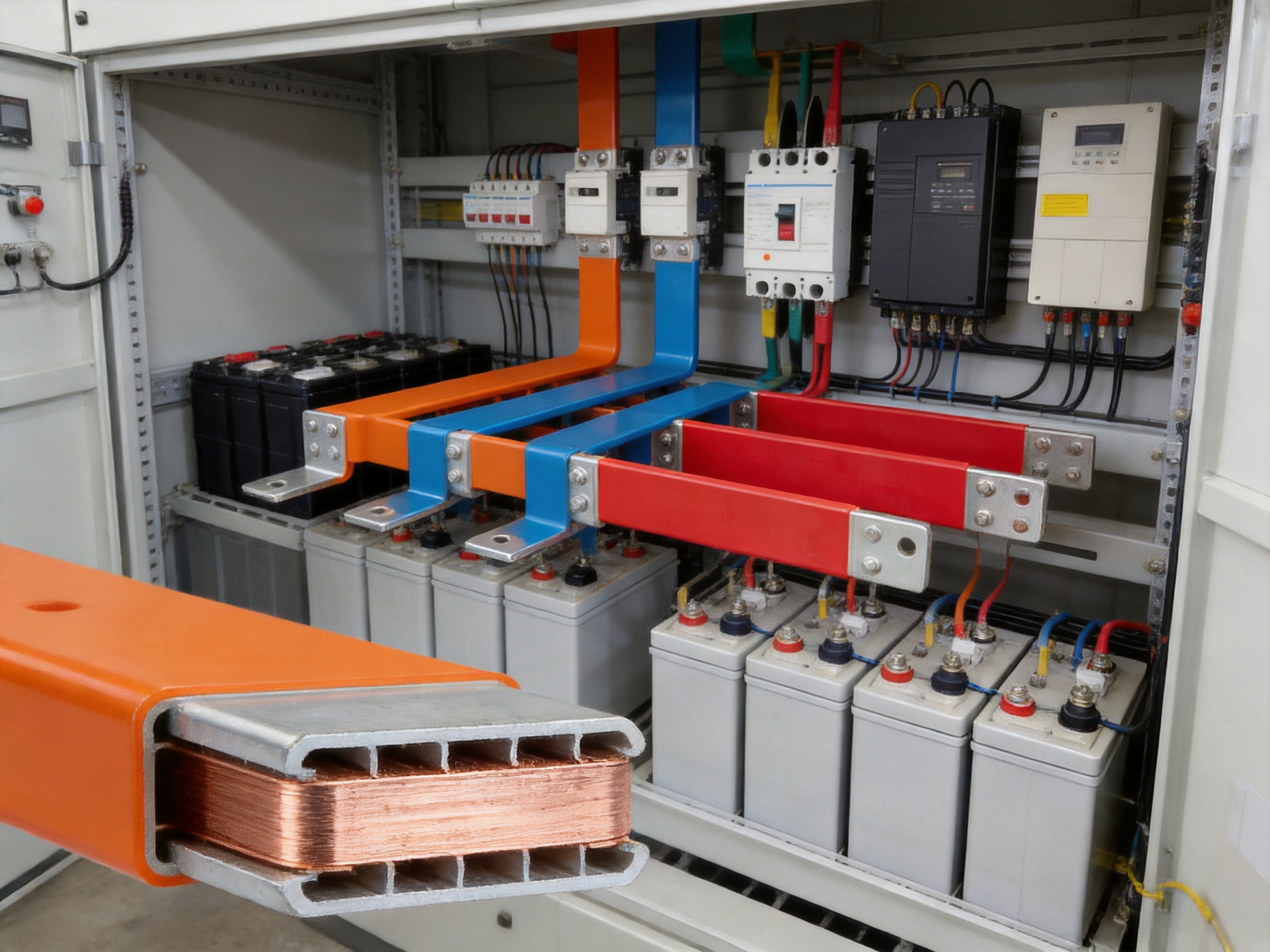
Manufacturing Strengths of a Specialized Supplier
A specialized busbar manufacturer offers advantages beyond basic metal cutting. The company must understand electrical design, material behavior, insulation processes, high-current connections, and the manufacturing limitations of complex shapes.
Zhejiang Zhongyan New Energy Co., Ltd. focuses on new energy conductive components and precision electrical connection solutions. Its product experience includes high-voltage electrical copper foil soft connections, special-shaped soft connections, battery soft connections, and related conductive parts. This background is relevant to insulated busbar production because many of the same requirements apply: low resistance, reliable connection, dimensional control, vibration resistance, and stable performance under demanding conditions.
The company brings together experienced engineers and technical teams and operates professional production equipment for design, processing, and testing. Its stated capabilities cover product design, research and development, manufacturing, and customized solution support.
Established in 2022, the company has developed expertise in new energy precision components, including battery soft connections. It uses independently developed polymer diffusion welding and laser technology patents in the production of components designed for low internal resistance and high reliability. These capabilities strengthen its understanding of high-current connection design and precision joining.
The company has also supplied products to leading enterprises in the new energy sector, including BYD, CATL, and Jaguar. Such project experience can help a manufacturer understand the importance of traceability, repeatability, design review, and consistent quality in automotive and energy applications. Specific product approvals and customer requirements should always be confirmed for each project.
Integrated Engineering Support
Many busbar projects begin with incomplete information. A customer may provide a hand sketch, a three-dimensional model, a sample, or a preliminary drawing. An experienced supplier can review the proposed structure and identify potential issues related to bending, insulation clearance, hole accessibility, coating coverage, terminal contact, and installation sequence.
OEM and ODM support can be provided based on CAD, DXF, PDF, or other technical documents. Engineering teams may help convert a design concept into a production-ready drawing, confirm material thickness, recommend suitable insulation, and identify areas that require masking or special finishing.
Support for Prototypes and Production
New energy equipment often requires several design revisions before mass production. A capable manufacturer should be able to support prototype development, sample approval, small-batch production, and volume manufacturing while maintaining control over dimensions and process parameters.
Prototype support is especially valuable for complex three-dimensional busbars. It allows the customer to verify fit, connection sequence, insulation clearances, and thermal behavior before committing to larger volumes.
Quality and Process Management
Consistent quality requires more than final inspection. It depends on incoming material control, equipment maintenance, process parameter management, operator training, in-process checks, and final verification.
Important inspection points may include:
Conductor material and thickness.
Overall length, width, and bend dimensions.
Hole position, hole diameter, and threaded features.
Surface cleanliness and burr condition.
Coating thickness and visual uniformity.
Adhesion of the PVC or powder coating.
Insulation integrity and dielectric performance.
Terminal contact area and exposed metal dimensions.
Color, packaging, and product identification.
The exact inspection plan should reflect the product drawing, customer specification, applicable standards, and risk level of the application.
Application Areas
Electric Vehicles and Battery Packs
Electric vehicles require compact, reliable high-current connections between battery modules, busbar assemblies, contactors, fuses, inverters, and other power electronics. Insulated busbars can help reduce the risk of accidental contact inside battery enclosures while providing a controlled current path.
Because battery packs are exposed to vibration, temperature changes, and limited installation space, the busbar must be designed with both electrical and mechanical considerations in mind. Custom bends, mounting holes, insulated sections, and connection pads can help the busbar fit the pack architecture.
Energy Storage Systems
Stationary and mobile energy storage systems contain battery racks, power conversion equipment, protection devices, and distribution assemblies. Insulated busbars can be used to connect modules and distribution points while supporting safer maintenance and improved internal organization.
Energy storage equipment may operate for long periods under continuous load. Low resistance, controlled temperature rise, durable insulation, and resistance to humidity and dust are therefore important considerations.
Power Distribution Cabinets and Switchgear
Switchgear and distribution cabinets frequently use busbars to distribute power among breakers, switches, terminals, and outgoing circuits. Insulated busbars can support compact arrangements and reduce the need for separate insulating shields.
Color-coded insulation may help installers identify phases or circuit functions. Custom holes and bends can simplify connection to breakers and terminal assemblies while maintaining an orderly internal layout.
UPS Systems and Inverters
Uninterruptible power supplies and inverters contain high-current DC and AC sections. Busbars can connect batteries, capacitors, switching devices, and output distribution components. Insulated designs are beneficial where high voltage and dense component placement create increased clearance and contact concerns.
Electric Motors and Industrial Drives
Industrial drives and motor control systems may require compact conductive links between power modules, terminals, filters, and switching components. Insulated busbars can resist vibration and help protect conductors in equipment that experiences repeated electrical and mechanical cycles.
New Energy Power Systems
Solar, wind, hydrogen-related, and other new energy systems often include power converters, battery storage, distribution equipment, and high-current switching assemblies. Custom busbars can simplify the interconnection of these subsystems and contribute to a more organized cabinet or module design.
Design Considerations for Selecting an Insulated Busbar
Current and Thermal Requirements
The design must specify continuous current, peak current, fault current, duty cycle, and permissible temperature rise. A busbar that is appropriate for short-duration current may not be suitable for continuous operation. Engineers should evaluate the conductor cross-section, cooling conditions, enclosure ventilation, and proximity of heat-sensitive components.
Voltage and Insulation Requirements
Voltage level, transient conditions, pollution degree, clearance, creepage, and dielectric test requirements should be considered. The insulation thickness and material should be selected according to the system design and applicable standards rather than by appearance alone.
Mechanical Layout
The busbar should fit the enclosure or module without forced alignment. Mounting points should support the component without creating unnecessary stress. Bend radii, terminal heights, hole locations, and access for tools must be checked during the design stage.
Connection Method
Bolted, clamped, welded, brazed, or other connection methods may be used depending on the application. The selected method affects exposed contact areas, surface treatment, hole design, and assembly instructions.
Environmental Conditions
Humidity, water exposure, dust, oil, salt spray, vibration, chemicals, and temperature cycling can all influence material and coating selection. A PVC coating or epoxy powder coating should be selected and validated for the actual service environment.
Regulatory and Customer Requirements
Potential requirements may include RoHS, CE, IEC-related specifications, UL94 V-0 flame-retardant performance, customer-specific insulation tests, and automotive or energy storage quality procedures. These requirements should be identified before production because they may influence material selection, coating formulation, testing, labeling, and documentation.
Customization Options
Insulated busbars can be customized in many ways to match the customer’s equipment:
Material: T2 or C11000 copper, 1060 or 1070 aluminum, or another approved grade.
Thickness and width: Selected according to current capacity, mechanical strength, and available space.
Length: Manufactured to suit the exact distance between connection points.
Shape: Straight, L-shaped, U-shaped, stepped, offset, or special three-dimensional geometry.
Holes: Round holes, slots, mounting holes, terminal holes, or customer-defined patterns.
Threads: Tapped holes or other fastening features.
Insulation: PVC dipping or epoxy powder coating.
Insulation thickness: Approximately 0.5 to 2.0 millimeters for customizable designs, subject to project requirements.
Color: Red, black, blue, gray, yellow, green, or another specified color.
Exposed areas: Defined terminal pads, contact faces, grounding points, or connection sections.
Surface treatment: Cleaning, deburring, polishing, selected plating, or other approved treatment.
Documentation: CAD, DXF, PDF, samples, technical drawings, inspection reports, and packaging specifications.
This degree of customization makes insulated busbars suitable for both standard equipment platforms and highly specialized assemblies.
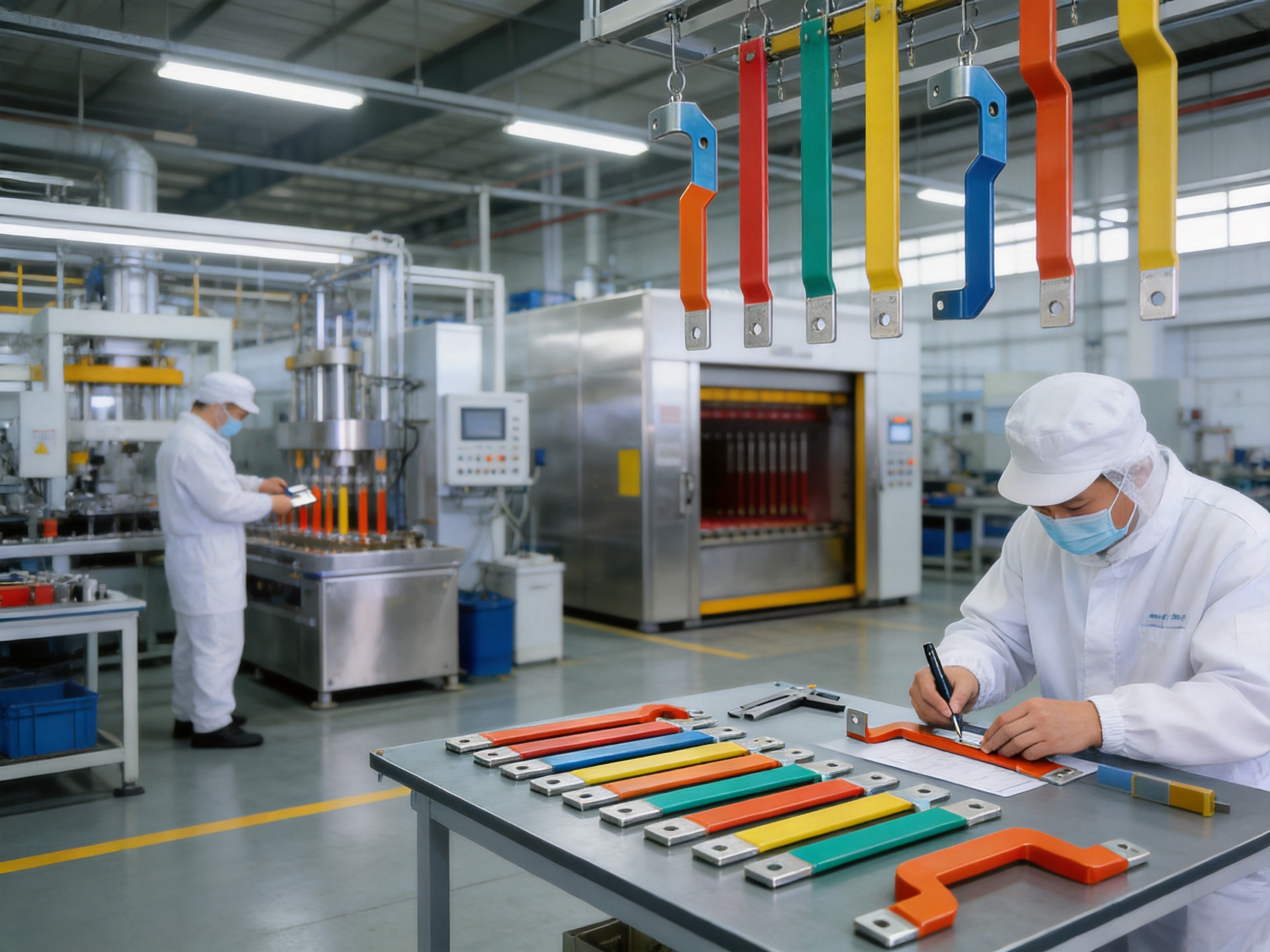
Why Customized Insulated Busbars Can Improve System Performance
A customized busbar is designed around the equipment rather than forcing the equipment to accommodate a generic part. This can provide several practical benefits.
First, it can reduce the number of intermediate joints. Fewer joints may simplify assembly and reduce potential points of increased resistance. Second, the busbar can be formed to minimize unnecessary routing and support hardware. Third, an integrated insulating layer can reduce the need for separate sleeves, covers, and barriers.
Customized geometry may also improve production consistency. When a busbar arrives preformed and pre-insulated, operators do not need to manually bend, wrap, or insulate the conductor during final assembly. This can shorten installation time and reduce variation between units.
In high-volume manufacturing, these advantages can influence labor cost, assembly cycle time, quality control, and field service. In lower-volume or specialized systems, customized busbars can help solve space and connection problems that standard cables or flat bars cannot address efficiently.
Installation and Handling Recommendations
Even a high-quality insulated busbar should be handled correctly. The component should be inspected before installation to confirm that the coating is intact and that no cracks, cuts, peeling, or exposed conductive areas are present outside the designated contact zones.
Installation personnel should avoid dragging coated surfaces across sharp edges. Tools should be selected to prevent damage to the insulation. Bolts, washers, and contact surfaces should be installed according to the specified torque and assembly procedure.
Connection areas must be clean and free of contamination. If a terminal surface has been intentionally left uncoated, it should not be covered with paint, dirt, or an unsuitable sealant. Contact pressure should be distributed evenly, and the completed joint should be checked for alignment and mechanical stability.
Busbars should be supported at the locations indicated by the design. Unsupported lengths may experience vibration or movement, especially in vehicle and industrial applications. Where the system is exposed to thermal cycling, designers should also consider the relative expansion of the busbar, insulation, fasteners, and supporting structures.
Technical Specifications at a Glance
| Specification | Available or Typical Option |
|---|---|
| Conductor materials | T2/C11000 copper; 1060/1070 aluminum |
| Insulation processes | PVC dipping; epoxy powder coating |
| Insulation thickness | Approximately 0.5 mm to 2.0 mm, customizable |
| Working temperature | Approximately -50°C to 160°C, depending on design and material |
| Processing methods | Laser cutting, bending, punching, drilling, tapping, and finishing |
| Insulation colors | Red, black, blue, gray, yellow, green, and custom colors |
| Documentation support | CAD, DXF, PDF, samples, and customer drawings |
| Potential compliance requirements | RoHS, CE, IEC, and optional UL94 V-0, subject to project validation |
| Typical uses | EVs, battery packs, ESS, switchgear, cabinets, UPS, inverters, motors, and industrial equipment |
The values in this table are general production options. Final specifications should be confirmed through an engineering review and approved product drawing.
Quality Verification and Reliability
Reliability is determined by the complete product system, including the conductor, insulation, terminals, mounting arrangement, and operating environment. A suitable verification plan may include dimensional inspection, coating thickness measurement, visual examination, adhesion checks, electrical resistance testing, insulation resistance testing, dielectric withstand testing, and temperature-related evaluation.
For applications exposed to vibration, vibration testing or mechanical retention evaluation may be appropriate. For outdoor or humid environments, moisture resistance and corrosion-related testing may be required. For battery and automotive applications, thermal cycling and long-term durability validation may also be considered.
Manufacturers and customers should agree on the applicable tests before mass production. Clear acceptance criteria help prevent misunderstanding and ensure that the finished busbar matches the intended use.
Frequently Asked Questions
What is the main purpose of coating a copper or aluminum busbar?
The coating provides electrical insulation and protects the conductor from accidental contact, short circuits, moisture, dust, oil, corrosion, scratches, and other environmental or mechanical influences. It also supports compact installation by reducing dependence on separate insulating barriers.
Is PVC dipping better than powder coating?
Neither process is universally better. PVC dipping may be suitable where a resilient insulating layer, color coding, and practical environmental protection are required. Epoxy powder coating may be preferred where strong adhesion, a durable surface, and resistance to industrial exposure are important. The correct choice depends on voltage, temperature, geometry, environment, assembly method, and customer specifications.
Can both copper and aluminum be used?
Yes. Copper grades such as T2 and C11000 are suitable when high conductivity and strong contact performance are priorities. Aluminum grades such as 1060 and 1070 may be selected when low weight or specific material economics are important. The connection design must account for the characteristics of the chosen metal.
Can the busbar be bent into a special shape?
Yes. Busbars can be manufactured with customized bends, offsets, steps, mounting features, and three-dimensional forms. The design should define bend radii, dimensions, hole locations, and terminal positions before production.
What insulation thickness is available?
The supplied technical information identifies a customizable range of approximately 0.5 millimeters to 2.0 millimeters. The final thickness depends on the voltage, insulation requirements, geometry, coating process, and assembly tolerance.
Can some areas remain uncoated?
Yes. Terminal pads, grounding points, and other electrical contact areas may be masked or finished separately. The uncoated areas should be clearly identified on the drawing to ensure correct processing and safe assembly.
What files are needed for a quotation?
A CAD, DXF, PDF, three-dimensional model, technical sketch, or physical sample may be used. It is also helpful to provide material, thickness, current, voltage, insulation, color, quantity, tolerance, testing, and packaging requirements.
Are insulated busbars suitable for electric vehicles and battery systems?
Yes. They are commonly considered for battery packs, high-voltage distribution, inverters, contactor assemblies, energy storage systems, and other new energy equipment. The final design must be validated for current, voltage, temperature, vibration, insulation, and installation conditions.
How can a manufacturer support a new project?
A specialized manufacturer can review drawings, recommend materials and coating processes, develop prototypes, manufacture samples, perform dimensional and electrical checks, revise the design, and support volume production. This engineering involvement can reduce development risks and improve assembly efficiency.
What standards may apply?
Possible requirements include RoHS, CE, IEC-related specifications, and optional UL94 V-0 flame-retardant performance. The exact standards depend on the finished equipment, market, application, and customer approval process. Compliance should be confirmed project by project.
Conclusion
PVC-dipped and powder-coated insulated busbars combine the conductivity of copper or aluminum with electrical insulation, environmental protection, mechanical durability, and design flexibility. They are well suited to modern systems where high current, compact installation, safety, and long service life must be achieved at the same time.
Compared with bare busbars, insulated versions reduce the risk of accidental contact and can simplify high-density layouts. Compared with multiple cable assemblies, customized busbars may reduce routing space, connection points, and assembly operations. Their value is greatest when they are designed around the exact geometry and electrical requirements of the equipment.
Zhejiang Zhongyan New Energy Co., Ltd. supports these requirements through experience in new energy conductive components, battery soft connections, high-voltage copper foil connections, special-shaped connections, laser processing, polymer diffusion welding, precision manufacturing, and customized engineering. Its capabilities cover design, development, production, and solution support for demanding power transmission and energy applications.
For project developers, equipment manufacturers, and electrical engineers, the best results come from early cooperation between the design team and the busbar supplier. By confirming material, current, insulation, geometry, connection method, environmental conditions, testing, and compliance requirements at the beginning, customers can obtain a busbar that is safer, easier to install, more consistent in production, and better matched to the performance goals of the finished system.
References
1. IEC technical principles for low-voltage electrical assemblies, busbar systems, insulation coordination, and electrical safety.
2. General engineering practices for copper and aluminum conductors used in power distribution equipment.
3. RoHS requirements for the restriction of hazardous substances in electrical and electronic equipment.
4. CE conformity principles applicable to electrical equipment placed on relevant markets.
5. UL94 flammability classification principles for polymeric materials used in electrical and electronic components.
6. Manufacturer-provided technical information for PVC-dipped and epoxy powder-coated insulated busbars.
7. Manufacturer-provided information on copper foil soft connections, battery soft connections, polymer diffusion welding, laser processing, and new energy conductive components.
Product: PVC Dipped & Powder Coated Busbar | Insulated Copper & Aluminum Busbar

Driven by the development of new energy and aiming for "zero carbon".
Copyright © Zhejiang Zhongyan New Energy Co., Ltd. All Rights Reserved.
