 English
 Español

PBCR Series Soft Braided Tape: High-Flexibility Copper Connections for High-Current Busbar Systems
Introduction
Modern electrical equipment increasingly requires connection components that combine high current capacity, mechanical flexibility, vibration resistance, compact installation, and dependable long-term conductivity. Traditional rigid busbars are highly effective for fixed power distribution, but they may not be suitable where equipment movement, thermal expansion, vibration, installation tolerances, or repeated mechanical stress are present. A flexible copper connector is often required to bridge these interfaces while maintaining a stable and low-resistance electrical path.
The PBCR Series Soft Braided Tape is designed for this purpose. It is a flexible copper connection product belonging to the category of stranded copper wires and stranded copper connectors. The product uses electrolytic copper wires with an individual wire diameter of approximately 0.15 mm. Its fine braided structure delivers high flexibility while maintaining the current-carrying capability required for demanding power applications.
Unlike a basic strip of braided copper that requires additional terminal preparation, the PBCR Series is supplied as an integrated connector with mounting holes. This ready-to-use structure helps eliminate separate tinning, pressing, and terminal assembly processes. As a result, the product can simplify installation, reduce the number of components in a connection, and improve consistency during production or field servicing.
PBCR Soft Braided Tape is suitable for transformer busbar slot connections, grounding systems, welding applications, switchgear, power distribution equipment, and other high-current electrical assemblies. Depending on the selected cross-sectional area and configuration, the product can support current levels ranging from standard industrial requirements to applications approaching 4,600 amperes.
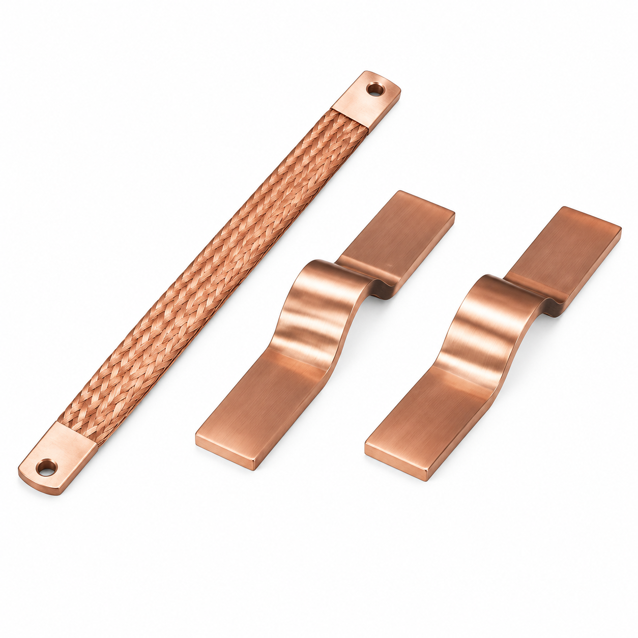
PBCR Series Soft Braided Tape
What Is a Soft Braided Copper Connector?
A soft braided copper connector is an electrical connection component made by interweaving numerous fine copper wires into a flexible conductive body. The braid can bend, compress, and accommodate movement more effectively than a solid copper bar or a conventional rigid connector. Copper provides excellent electrical conductivity, while the braided construction creates mechanical flexibility without requiring a hinge, cable lug, or complex articulated assembly.
The term “soft” describes the physical behavior of the braid rather than a lack of strength. The product is engineered to remain conductive and mechanically stable while absorbing movement and vibration. A fine-wire construction is especially useful where the connector must be routed through a confined space, aligned with mounting holes, or connected between components that do not remain perfectly stationary.
In a typical electrical system, a soft braided connector may be installed between a busbar and a transformer terminal, between a switchgear assembly and a moving panel, or between power equipment and a grounding point. It can also be used in high-current battery, energy-storage, welding, and power-conversion systems where space limitations and vibration make rigid connections unsuitable.
The PBCR Series combines the basic benefits of copper braid with an integrated connection design. Instead of requiring a separate terminal lug to be attached at each end, the connector includes formed ends with holes for bolted installation. This helps maintain a straightforward current path and reduces assembly work.
Fine electrolytic copper wires
The PBCR Series uses electrolytic copper wire with a nominal diameter of 0.15 mm. The use of many small wires allows the braid to flex repeatedly with lower localized stress than a solid conductor. Fine wires also enable the connector to conform to different installation positions and absorb small amounts of movement caused by thermal expansion or equipment vibration.
Electrolytic copper is widely used in power connections because it offers high electrical conductivity and good forming characteristics. In a braided structure, these characteristics support both efficient current transmission and reliable mechanical shaping during manufacturing.
Integrated connector ends
Each connector is manufactured with integrated connection ends and mounting holes. This configuration is intended to be ready for installation after the required dimensional and electrical specifications have been confirmed. It can help reduce dependence on separate cable lugs, crimping tools, pressing operations, or field-applied terminal treatments.
The integrated design is particularly valuable for repeat production. When the same connector configuration is used across a product family, operators can install the part using a consistent bolted procedure. This may improve assembly efficiency and reduce the risk of variation caused by manual terminal preparation.
Main Advantages of the PBCR Series
High electrical conductivity
Copper is the primary conductive material in the PBCR Series, allowing the connector to carry substantial current while maintaining a compact cross section. The available configurations include cross-sectional areas of 70, 100, 120, 185, and 240 square millimeters. The supplied specifications list current-carrying values at both a 30 kelvin temperature rise and a 50 kelvin temperature rise.
For example, the 70 square millimeter versions are listed with current capacities of 226 amperes at a 30 kelvin temperature rise and 362 amperes at a 50 kelvin temperature rise. The 240 square millimeter versions are listed with current capacities of 556 amperes and 890 amperes under the same respective conditions. These figures provide a useful reference for preliminary component selection, although final application ratings should always be verified against the complete installation environment.
High flexibility
Flexibility is one of the defining advantages of the PBCR Series. The fine-wire braid can accommodate bending and movement more effectively than a rigid copper bar. This makes the connector suitable for interfaces where components expand, vibrate, or require adjustment during installation.
High flexibility also helps installers work inside crowded electrical cabinets and equipment compartments. A rigid bar often requires precise alignment before holes can be matched. A braided connector can provide greater tolerance for small differences in position, making it easier to connect terminals that are not perfectly aligned.
Vibration resistance
Electrical systems used in transportation, industrial machinery, transformers, power converters, and energy-storage equipment may experience continuous or intermittent vibration. A rigid connection can transfer mechanical stress directly to terminals, bolts, insulators, or busbar supports. Over time, this stress may contribute to loosening, fatigue, cracking, or damage at the connection interface.
The soft braided construction helps reduce the transmission of vibration through the connection. Instead of forcing the entire assembly to move as a rigid unit, the braid can absorb a portion of the movement. This feature is especially important in applications where electrical continuity must be maintained despite mechanical disturbance.
Reduced installation weight
The PBCR Series is designed as an integrated connection rather than a combination of a flexible conductor, separate terminal ends, and additional pressed or soldered components. This all-in-one approach can reduce the overall weight of the connection assembly. Lower weight is beneficial in equipment where every component contributes to the load on a support structure, terminal, or enclosure.
Weight reduction can also simplify handling during installation. A lighter connector is easier to position, especially when technicians are working inside a cabinet or at an elevated installation point. In assemblies with numerous parallel connections, the cumulative weight reduction can become significant.
Ready-to-use configuration
The integrated holes and formed ends allow the product to be installed using a bolted connection method. The design avoids the need for tinning or pressing joints as part of the normal installation process. This can shorten assembly time and decrease the number of tools and consumables required by the production line.
Reducing secondary operations can also improve process control. Tinning and pressing quality may vary depending on operator technique, equipment settings, surface preparation, and inspection procedures. A manufactured integrated connector provides a more consistent starting point for assembly.
Support for high-current applications
PBCR Soft Braided Tape is intended for high-current connections, including applications described with strength of up to 4,600 amperes. The exact permissible current depends on the selected cross section, length, installation orientation, ambient conditions, permissible temperature rise, ventilation, contact pressure, and surrounding components.
The product should therefore be selected as part of a complete thermal and electrical design process. The stated current values are useful technical references, but they should not replace system-level validation. Engineers should evaluate temperature rise, short-circuit forces, mounting hardware, insulation clearance, and the effect of adjacent conductors before final approval.
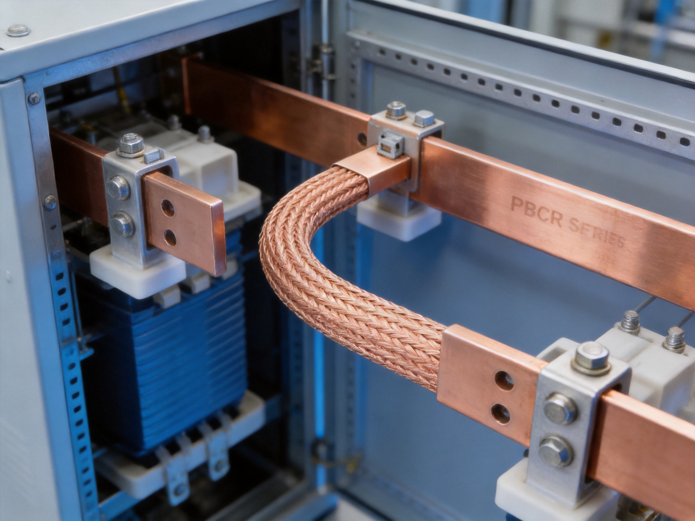
Comparison with Conventional Connection Solutions
Compared with rigid copper busbars
Rigid copper busbars are well suited to fixed, accurately aligned connections. They provide a stable current path and can be formed into complex shapes through cutting, bending, punching, and surface treatment. However, a rigid busbar has limited ability to absorb movement. If two connected components move relative to one another, mechanical stress may be transferred to the mounting points.
The PBCR Series is more appropriate when flexibility is a primary requirement. It can compensate for small positional differences, thermal movement, and vibration while continuing to conduct current. This makes it a complementary product rather than a universal replacement for rigid busbars. In a complete busbar system, rigid bars can provide the main distribution path while soft braided connectors are used at moving, vibrating, or expansion-sensitive interfaces.
Compared with ordinary copper braid
Ordinary copper braid may provide excellent flexibility, but it often requires separate terminals to connect the braid to equipment. These additional components can increase assembly time, weight, and the number of potential electrical interfaces. A poorly prepared terminal can also create localized resistance and heating.
The PBCR Series integrates the connection ends and mounting holes into the product. This can reduce the need for additional terminal components and make the connection more convenient to install. The integrated structure is also useful for standardized equipment designs where repeatability and fast assembly are important.
Compared with flexible cable
Flexible cable is commonly used for power connections because it bends easily and can be routed through complex paths. However, cable requires insulation, cable lugs, crimping, bending-radius control, and terminal preparation. In high-current applications, the cable assembly may become large, heavy, and difficult to install.
A bare copper braided connector can provide a compact alternative where insulation is not required from the connector itself or where the surrounding assembly provides the required protection. It can also offer a broad, low-profile connection between flat terminals. The correct choice depends on insulation requirements, touch protection, environmental exposure, routing distance, and applicable safety standards.
Compared with manually fabricated connections
Manually fabricated flexible connections may involve cutting braid, attaching terminals, pressing joints, applying surface treatments, and inspecting each assembly. Such processes can be suitable for prototypes or low-volume repairs, but they may create inconsistency in high-volume production.
A manufactured PBCR connector offers a defined part number, cross section, dimensional configuration, and packaging unit. This supports controlled procurement, repeatable installation, and easier replacement. It also allows equipment designers to specify a known component rather than relying on a custom assembly made at the installation site.
Product Configurations and Technical Selection
The PBCR Series is available in several cross-sectional areas and lengths. Product designations identify the approximate cross section and configuration. The range includes 70, 100, 120, 185, and 240 square millimeters, with listed lengths or connection dimensions of 230, 330, and 430 millimeters depending on the model.
Hole and end dimensions also vary between models. Several 70 and 100 square millimeter versions are identified with an 8 to 10 millimeter end-hole configuration. The 120 square millimeter models use a 10 millimeter configuration, while the 185 and 240 square millimeter models are identified with 10 to 12 millimeter connection dimensions.
The following table summarizes the supplied product information. Dimension fields are reproduced according to the provided specification structure. Engineers should confirm the latest dimensional drawing before production use, particularly where clearance, bolt size, mounting pitch, and hole tolerances are critical.
| Part Number | Description | Cross Section (mm²) | Current at Δ30K (A) | Current at Δ50K (A) | Listed Dimension 1 (mm) | Listed Dimension 2 (mm) | Length (mm) | Diameter 1 (mm) | Diameter 2 (mm) | A1 (mm) | A2 (mm) | J (mm) | M (mm) | Packaging | Weight (kg) |
|---|---|---|---|---|---|---|---|---|---|---|---|---|---|---|---|
| 23000402 | PBCR 70-230-8-10 | 70 | 226 | 362 | 291 | 466 | 230 | 8.5 | 10.5 | 9 | 11 | 20 | 4.3 | 2 | 0.17 |
| 23000403 | PBCR 70-330-8-10 | 70 | 226 | 362 | 291 | 466 | 330 | 8.5 | 10.5 | 9 | 11 | 20 | 4.3 | 2 | 0.24 |
| 23000404 | PBCR 70-430-8-10 | 70 | 226 | 362 | 291 | 466 | 430 | 8.5 | 10.5 | 9 | 11 | 20 | 4.3 | 2 | 0.30 |
| 23000405 | PBCR 100-230-8-10 | 100 | 298 | 477 | 385 | 616 | 230 | 8.5 | 10.5 | 9 | 11 | 24 | 5 | 2 | 0.24 |
| 23000406 | PBCR 100-330-8-10 | 100 | 298 | 477 | 385 | 616 | 330 | 8.5 | 10.5 | 9 | 11 | 24 | 5 | 2 | 0.34 |
| 23000407 | PBCR 100-430-8-10 | 100 | 298 | 477 | 385 | 616 | 430 | 8.5 | 10.5 | 9 | 11 | 24 | 5 | 2 | 0.44 |
| 23000408 | PBCR 120-230-10 | 120 | 363 | 581 | 468 | 749 | 230 | 10.5 | 10.5 | 11 | 11 | 32 | 4.4 | 2 | 0.29 |
| 23000409 | PBCR 120-330-10 | 120 | 363 | 581 | 468 | 749 | 330 | 10.5 | 10.5 | 11 | 11 | 32 | 4.4 | 2 | 0.41 |
| 23000410 | PBCR 120-430-10 | 120 | 363 | 581 | 468 | 749 | 430 | 10.5 | 10.5 | 11 | 11 | 32 | 4.4 | 2 | 0.53 |
| 23000411 | PBCR 185-330-10-12 | 185 | 416 | 666 | 537 | 859 | 330 | 10.5 | 12.5 | 12 | 14 | 32 | 7.1 | 2 | 0.64 |
| 23000412 | PBCR 185-430-10-12 | 185 | 416 | 666 | 537 | 859 | 430 | 10.5 | 12.5 | 12 | 14 | 32 | 7.1 | 2 | 0.82 |
| 23000413 | PBCR 240-330-10-12 | 240 | 556 | 890 | 718 | 1149 | 330 | 10.5 | 12.5 | 12 | 14 | 32 | 9.2 | 2 | 0.83 |
| 23000414 | PBCR 240-430-10-12 | 240 | 556 | 890 | 718 | 1149 | 430 | 10.5 | 12.5 | 12 | 14 | 32 | 9.2 | 2 | 1.07 |
How to choose the cross section
The cross section should be selected according to the continuous operating current, expected temperature rise, installation conditions, and available space. A larger cross section generally provides greater current-carrying capacity, but it may also increase weight, cost, and installation space. The best selection balances electrical performance with mechanical and economic requirements.
Designers should consider whether the connector operates in an enclosed cabinet, an open and ventilated environment, or near heat-producing components. Adjacent conductors, enclosure temperature, duty cycle, and current waveform may all affect the actual operating temperature. Connections exposed to overloads or high ambient temperatures may require additional design margin.
How to choose the length
The connector length should allow the braid to reach both terminals without being stretched, sharply folded, or forced into an unsuitable bend. A connector that is too short may transfer mechanical stress to the terminals. A connector that is excessively long may create unnecessary loops, interfere with nearby components, or increase inductive effects in certain high-current layouts.
The listed 230, 330, and 430 millimeter configurations provide options for different mounting distances. Before ordering, the installer should verify the terminal-to-terminal distance, bolt spacing, required bend direction, and clearance from grounded or energized components.
How to choose the hole configuration
The mounting holes must match the terminal bolts or studs used in the equipment. The hole configuration also affects contact area, bolt loading, installation access, and the ability to maintain a stable joint under vibration. Bolts, washers, nuts, and torque values should be selected according to the equipment design and applicable electrical installation practices.
Where corrosion, contamination, or repeated thermal cycling is expected, the contact interface should be properly prepared and protected. The braid should be mounted flat and should not be twisted around the bolt unless the approved installation method specifically permits it.
Applications in Electrical and Energy Systems
Transformer busbar slot connections
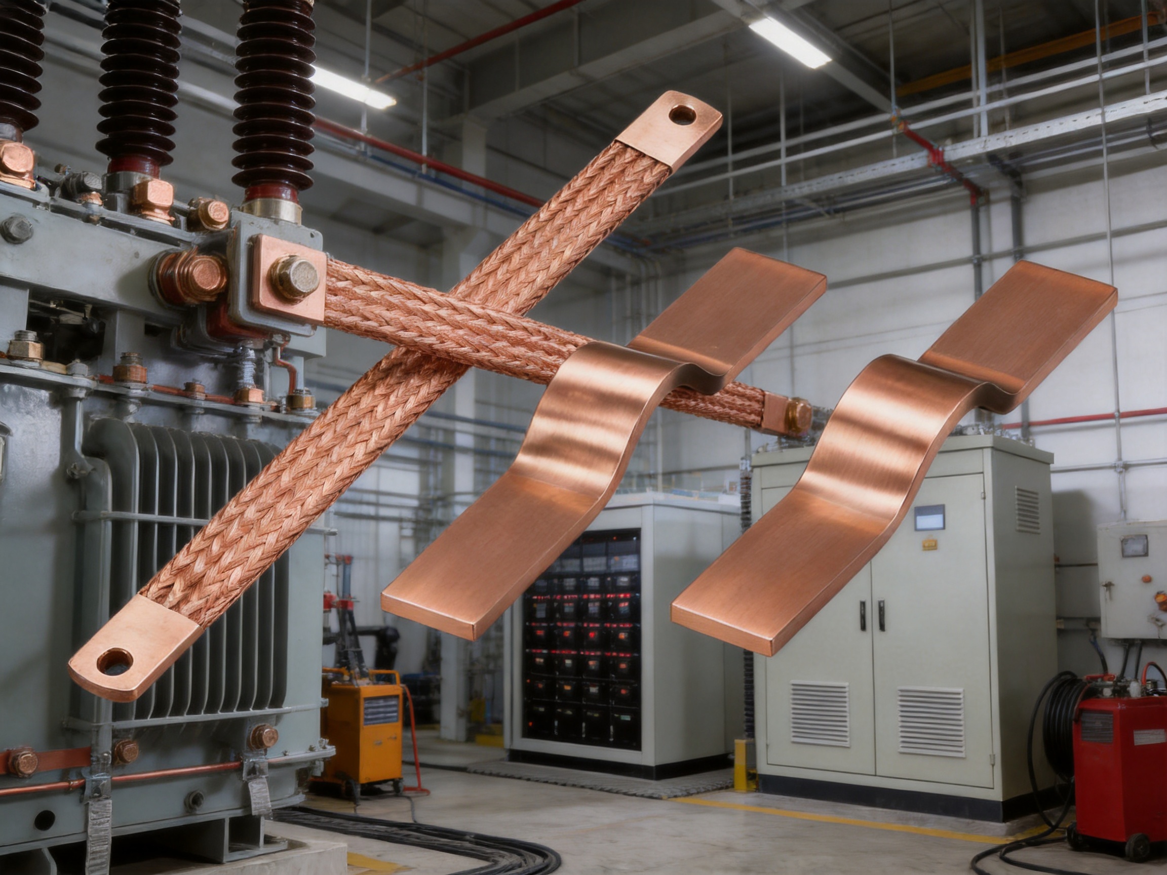
Transformer connections can experience thermal expansion, electromagnetic forces, and mechanical vibration. A soft braided connector can provide a flexible transition between the transformer terminal and the busbar system. This helps reduce stress at the connection points while preserving the required current path.
The PBCR Series is identified as a preferred product for transformer busbar slot connections. Its flexible body can be routed within the available space, while its integrated ends support a direct bolted connection. The ability to select different lengths and cross sections allows the connector to be adapted to different transformer layouts.
Switchgear and power distribution equipment
Switchgear assemblies often contain busbars, circuit breakers, disconnectors, current transformers, and other components mounted within a compact enclosure. The relative position of these components may create a need for flexible connections, particularly at hinged panels, removable units, or vibration-sensitive interfaces.
PBCR connectors can be used between fixed and movable portions of an assembly when the electrical and safety design permits. Their low-profile braided construction can help preserve cabinet space while accommodating movement and installation tolerances.
Grounding and bonding
The supplied product information identifies a 100 square millimeter configuration for grounding and welding applications. Flexible copper braid is commonly useful for bonding equipment frames, doors, panels, transformer structures, and other conductive parts that require electrical continuity while allowing movement.
Grounding applications must be designed according to the expected fault current, clearing time, mechanical protection, environmental exposure, and relevant electrical codes. The nominal cross section alone does not determine suitability. Engineers should verify the short-circuit duty and ensure that the connector is installed so that it remains mechanically protected and electrically continuous.
Welding equipment
Welding equipment requires high-current connections that can withstand movement, vibration, and repeated operating cycles. A flexible copper braid can provide a useful connection between power sources, welding transformers, electrodes, and moving assemblies, subject to the equipment manufacturer’s specifications.
Because welding current may be intermittent and may involve high peak values, the selection should consider duty cycle as well as continuous current. The connector should also be protected from abrasion, spatter, excessive heat, and sharp bending during operation.
Battery and energy-storage equipment
Battery systems and energy-storage equipment contain numerous conductive interfaces within limited spaces. Flexible connectors can link busbars, battery modules, switching devices, inverters, and grounding structures while accommodating assembly tolerances and vibration.
The PBCR Series belongs to a broader product portfolio that includes battery soft connections, battery terminal insulation covers, cells contact systems, and battery storage connectors. This product-family approach can help system designers source complementary conductive components from a manufacturer with experience in new-energy connection systems.
Rail transit and industrial machinery
Rail vehicles and industrial machines are exposed to vibration and mechanical movement. Connections in these environments must maintain electrical continuity while tolerating dynamic operating conditions. The soft braided construction of the PBCR Series can support such applications where the current, environment, and protection requirements are compatible.
For transportation applications, additional validation may be required for fire behavior, environmental resistance, mechanical fatigue, insulation coordination, and electromagnetic performance. Product selection should be integrated with the relevant vehicle or machinery qualification program.
Advanced Manufacturing Capabilities
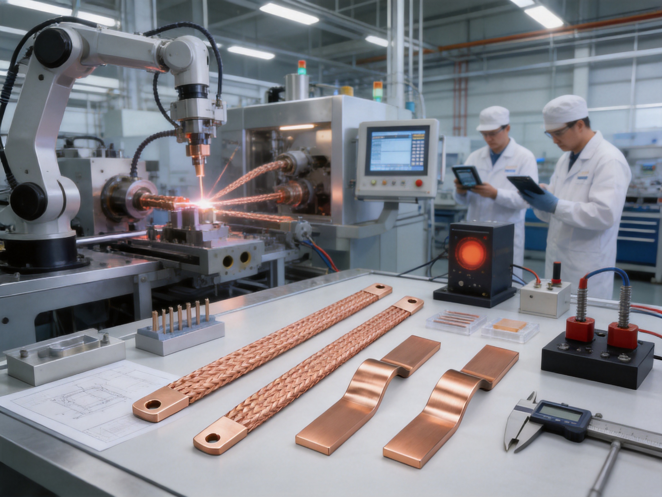
The performance of a flexible copper connector depends not only on the raw material but also on the accuracy of braiding, terminal formation, hole production, joining, inspection, and packaging. Zhejiang Zhongyan New Energy Co., Ltd. is a high-technology manufacturer specializing in new-energy conductive components and precision electrical connection solutions.
Experience in soft connection manufacturing
The company has an experienced engineering and technical team focused on soft connections and conductive components. Its capabilities cover product design, research and development, manufacturing, and solution development. This combination is important because flexible connectors are application-dependent products. Electrical capacity, flexibility, mounting geometry, temperature behavior, and mechanical durability must be considered together.
Rather than treating the connector as a generic length of copper braid, an experienced manufacturer can develop a configuration around the customer’s terminal position, current requirement, installation envelope, and operating conditions. This supports customized dimensions, hole patterns, cross sections, and assembly requirements.
Polymer diffusion welding technology
The company has independently developed polymer diffusion welding technologies for new-energy precision components. This technology is associated with the production of low-internal-resistance and highly reliable conductive connections. In suitable applications, advanced joining processes can reduce electrical resistance and improve the consistency of the connection interface.
Although the PBCR Series is a braided copper connector with integrated ends, the company’s wider joining expertise strengthens its ability to develop related soft connections and customized conductive assemblies. Process knowledge in welding and diffusion-based joining can help address complex requirements in battery systems, high-voltage components, and precision power connections.
Laser processing
Laser technology can support precise cutting, shaping, marking, and joining operations. In conductive component manufacturing, controlled laser processing can be useful where dimensional accuracy, repeatability, and localized energy input are required.
The use of advanced laser technology contributes to the development of customized components with demanding geometries. It can also support stable manufacturing of parts that require accurate interfaces, repeatable hole positions, or carefully controlled joining regions.
Quality and process management
Stable performance requires more than a good design. Manufacturing systems must control material quality, wire dimensions, braid formation, terminal shape, hole size, surface condition, and final inspection. The company states that it operates modern production and quality management systems to provide stable and consistent products and services.
For industrial customers, consistency is especially important because flexible connectors are often installed in large quantities. A small difference in terminal geometry or hole position can affect assembly time and contact quality. A controlled process helps reduce such variation and supports repeatable production across different orders.
Research and development integration
The company is developing a research and development system covering materials science, precision machining, testing, and verification. This integrated approach allows product performance to be evaluated from multiple perspectives. Material selection affects conductivity and flexibility. Precision machining affects fit and assembly. Testing verifies electrical, thermal, and mechanical behavior.
By combining these disciplines, the manufacturer can support both standard products and application-specific development. This is valuable for customers working on new battery platforms, power-distribution equipment, transportation systems, and energy-storage products where conventional catalog components may not provide the required combination of performance and geometry.
Customization and OEM Support
Every electrical system has different terminal locations, installation clearances, current requirements, and mechanical conditions. A flexible connector that works well in one assembly may not be ideal in another. Customization is therefore an important advantage when selecting a supplier.
Customization may include cross-sectional area, overall length, hole diameter, hole spacing, end dimensions, braid width, terminal shape, surface treatment, insulation, labeling, and packaging. The appropriate options depend on the intended application and the production quantity.
Design support
Customer drawings, samples, or application information can be used as the basis for product development. Important information includes continuous current, peak current, temperature limits, terminal material, bolt size, available space, expected movement, vibration conditions, and environmental exposure.
For new designs, the manufacturer can help evaluate whether a braided connector, laminated busbar, rigid busbar, copper foil connection, or another conductive component is most appropriate. This design-oriented approach can prevent problems caused by selecting a product based only on nominal current.
Prototype and production transition
A reliable OEM process should support the transition from prototype to volume production. Prototype parts can be used to verify fit, routing, bending behavior, contact pressure, and installation time. Once the design is approved, production documentation and inspection requirements can be standardized.
This transition is particularly important in battery and energy-storage equipment, where small changes to module layout may affect the required connector length and terminal geometry. A manufacturer with both engineering and manufacturing capability can respond more efficiently to such design changes.
Supply-chain advantages
Using a defined product series with clear part numbers can simplify procurement and inventory management. The PBCR range provides multiple cross sections and lengths, allowing customers to select a standard configuration where possible while retaining access to customized solutions when necessary.
Consistent packaging and part identification also help reduce warehouse errors. For high-volume assemblies, packaging quantities should be coordinated with production-line requirements to support efficient material handling and traceability.
Installation and Design Recommendations
Prepare the mounting surfaces
The mating surfaces should be clean, flat, and free from contamination that could increase contact resistance. Oxide, oil, dust, paint, and burrs should be removed or controlled according to the equipment design. The connection should not be installed over an uneven surface that prevents full contact.
Use suitable hardware
Bolts, nuts, washers, and other hardware should be selected for the electrical and mechanical duty of the connection. The hardware must provide adequate clamping force without damaging the braid or distorting the terminal ends. Torque should follow the equipment design or approved installation specification.
Avoid twisting and excessive bending
The connector should be installed in its natural orientation. Excessive twisting can concentrate stress in the terminal area and may reduce the effective contact surface. Sharp bends should be avoided unless they are specifically permitted by the product design.
The braid should have enough slack to accommodate expected movement. However, unnecessary loops and loose sections should be avoided because they may interfere with nearby components or become vulnerable to abrasion.
Check thermal conditions
After installation, the connection should be assessed under representative operating conditions. Temperature rise may be influenced by current, enclosure ventilation, contact resistance, nearby heat sources, and duty cycle. A thermal inspection can help identify poor contact, insufficient clamping, or an undersized connector.
Protect against environmental hazards
Where the connector is exposed to moisture, chemicals, salt spray, dust, abrasion, or accidental contact, suitable protective measures should be applied. Bare copper components may require enclosure protection, insulation barriers, coatings, or approved environmental treatments depending on the application.
Quality, Reliability, and Application Validation
Electrical reliability is determined by the complete connection system. The copper braid, integrated terminals, mounting hardware, mating busbars, and surrounding support structure all contribute to performance. A high-quality connector cannot compensate for poor installation or unsuitable system design.
Validation should include dimensional inspection, electrical resistance measurement, current-carrying testing, temperature-rise testing, mechanical movement, vibration, and visual examination. The exact test program depends on the application and customer requirements.
For transformer and switchgear applications, thermal cycling and vibration testing may be important. For battery and energy-storage systems, designers may also evaluate insulation coordination, short-circuit performance, fault-current behavior, and the effects of repeated charge and discharge cycles.
Where the connection is part of a safety-critical grounding or bonding path, the test program should confirm electrical continuity under the expected fault and environmental conditions. Documentation should identify the approved part number, installation method, inspection criteria, and replacement requirements.
Why Choose an Experienced Conductive Component Manufacturer?
Flexible conductive components are precision products. Their performance is affected by wire diameter, braid density, cross-sectional area, terminal formation, surface condition, dimensional accuracy, and joining quality. An experienced manufacturer can manage these factors through specialized equipment and established process controls.
Zhejiang Zhongyan New Energy Co., Ltd. focuses on conductive components for power transmission and distribution, electric vehicles, rail transit, communications, and energy storage. Its product scope includes copper foil soft connections, special-shaped soft connections, battery soft connections, laminated busbars, cell contact systems, battery storage connectors, and insulation-related components.
The company was established in 2022 and has developed capabilities in new-energy precision components, including battery soft connections. Its stated customer base includes leading enterprises such as BYD, CATL, and Jaguar. These customer relationships indicate experience with demanding industrial supply requirements, although each project should still be evaluated according to its own technical and quality criteria.
The company’s broader development direction includes lithium battery manufacturing and integrated battery cell and connection-system design. This creates an opportunity for customers to obtain not only an individual copper connector but also coordinated conductive components for larger battery and energy-storage assemblies.
For OEM customers, the combination of engineering support, advanced joining technology, precision manufacturing, and application knowledge can reduce development risk. It can also support the creation of customized components that are difficult to source from general electrical wholesalers.
PBCR Series Value for System Designers
From a system-design perspective, the PBCR Series provides a practical way to introduce flexibility into an otherwise rigid busbar arrangement. Rigid conductors can be used for efficient distribution, while soft braided connectors accommodate movement at selected interfaces. This hybrid approach can improve mechanical reliability without sacrificing the structural advantages of busbars.
The product’s integrated terminal design can reduce assembly complexity. Fewer separate components mean fewer parts to purchase, store, prepare, and inspect. For automated or semi-automated production, a standardized connector can also simplify work instructions and reduce installation variability.
The available cross sections and lengths support a broad range of current and physical configurations. Standardized options can shorten procurement time, while customized manufacturing can address special mounting geometries or project-specific requirements.
Another important benefit is the balance between conductivity and flexibility. A connection must not only carry current; it must also survive the mechanical environment. The PBCR Series is designed around this balance, making it suitable for applications where ordinary rigid bars, cables, or manually assembled braids may create compromises.
Frequently Asked Questions
What is the PBCR Series Soft Braided Tape used for?
The PBCR Series is used for flexible high-current electrical connections. Typical applications include transformer busbar slot connections, grounding and bonding, welding equipment, switchgear, power distribution equipment, energy-storage systems, and other electrical assemblies that require vibration resistance and mechanical flexibility.
What material is used in the braid?
The product uses electrolytic copper wires with an approximate individual wire diameter of 0.15 millimeters. The copper wires are braided to form a flexible conductive connector.
Does the connector require tinning or pressing during installation?
The product is supplied as an integrated connector with holes and is intended to be ready for use. Its design reduces or eliminates the need for separate tinning or pressing joints during normal installation. The approved assembly procedure should still be followed for the specific equipment.
What cross-sectional areas are available?
The supplied product range includes 70, 100, 120, 185, and 240 square millimeter configurations. Additional custom sizes may be considered according to application requirements and manufacturing feasibility.
What current can the PBCR Series carry?
The listed current values range from 226 amperes at a 30 kelvin temperature rise for the 70 square millimeter version to 556 amperes at a 30 kelvin temperature rise for the 240 square millimeter version. At a 50 kelvin temperature rise, the listed values range from 362 amperes to 890 amperes. The product description also identifies applications with strength of up to 4,600 amperes. Actual ratings must be confirmed for the complete installation and duty cycle.
Which lengths are available?
The listed models include 230, 330, and 430 millimeter configurations. The suitable length depends on terminal spacing, routing, required flexibility, and installation clearance.
Can the connector be customized?
Customization support is available for conductive components. Possible requirements may include length, cross section, hole configuration, terminal geometry, surface treatment, insulation, marking, and packaging. A technical drawing or sample is recommended for accurate evaluation.
Is the PBCR Series suitable for outdoor use?
The connector may be used in outdoor or exposed equipment only when the complete assembly provides suitable protection against moisture, corrosion, contamination, ultraviolet exposure, and mechanical damage. Environmental requirements should be reviewed before selecting the product.
Can the braid replace a grounding cable?
It may be suitable for certain grounding or bonding applications, including the identified 100 square millimeter grounding application, but suitability depends on fault current, duration, installation method, mechanical protection, and applicable regulations. A qualified electrical engineer should approve the design.
How should the connector be installed?
The connector should be mounted flat against clean mating surfaces using suitable bolts, washers, and nuts. It should not be twisted or sharply bent, and it should have sufficient slack to accommodate expected movement. Hardware torque and clearances should follow the equipment specification.
What information is needed for a quotation?
Useful information includes required current, temperature conditions, connector length, hole size and spacing, terminal material, installation environment, expected movement, quantity, packaging requirements, and a drawing or photograph of the intended assembly.
Conclusion
The PBCR Series Soft Braided Tape is a practical solution for electrical systems that need both high conductivity and mechanical flexibility. Its electrolytic copper braid, fine 0.15 millimeter wire construction, integrated mounting ends, and multiple cross-sectional options make it suitable for a wide variety of high-current connection tasks.
Its advantages over conventional rigid bars, ordinary un-terminated braid, flexible cable assemblies, and manually fabricated connectors include improved flexibility, vibration resistance, reduced assembly work, lower connection weight, and a ready-to-use integrated structure. These benefits can help designers improve installation efficiency and reduce mechanical stress at electrical interfaces.
The product is supported by a manufacturer with experience in new-energy conductive components, precision soft connections, polymer diffusion welding, laser technology, materials development, testing, and customized manufacturing. This combination of product capability and engineering support is valuable for customers developing transformer, switchgear, battery, energy-storage, electric-vehicle, rail-transit, and industrial equipment.
For the best result, the connector should be selected through a complete electrical, thermal, mechanical, and environmental review. When the cross section, length, hole configuration, mounting hardware, and protection method are correctly matched to the application, the PBCR Series can provide a dependable flexible connection for demanding power systems.
References
1. Product specification data for the PBCR Series Soft Braided Tape, including cross-sectional areas, current-carrying values, dimensions, packaging, and weight.
2. Copper Development Association, technical guidance on copper conductivity, current-carrying capacity, and electrical connection design.
3. International Electrotechnical Commission, general principles for low-voltage switchgear and controlgear assemblies.
4. International Electrotechnical Commission, guidance for power connections, conductor temperature rise, and electrical equipment testing.
5. Engineering design practices for flexible busbar connections, transformer interfaces, grounding conductors, and vibration-resistant electrical assemblies.
Product: PBCR Series Soft Braided Tape

Driven by the development of new energy and aiming for "zero carbon".
Copyright © Zhejiang Zhongyan New Energy Co., Ltd. All Rights Reserved.
