 English
 Español
Busbar Sizing and Calculation 2026: Resistance, Voltage Drop, Weight and Current Density
Search for a busbar calculator and you will find dozens of them, most returning a single number with no indication of where it came from. That number is worth very little unless you know which question it answered, because busbar sizing is really two separate calculations that are often confused with each other.
This guide sets out the physics behind the numbers — resistance, voltage drop, temperature rise, skin effect and inductance — with worked arithmetic you can follow and adapt. Every figure below is calculated from published material properties, so you can check the maths yourself.
Content
- Two different questions
- The material properties you need
- Step 1 — resistance from geometry
- Step 2 — correcting for temperature
- Step 3 — voltage drop and power loss
- Step 4 — current density, and why it is only a starting point
- Estimating temperature rise
- Skin effect: why DC sizing fails at high frequency
- Inductance: the loop matters, not the bar
- Weight: for shipping, structure and supports
- What no calculator can tell you
- Frequently asked questions
- Sizing a busbar with confidence
Two different questions
The first question is electrical: how much resistance does this bar add, and how much voltage does it lose at my current? That is straightforward geometry and material science, and it has an exact answer.
The second question is thermal: at what current does this bar's temperature rise exceed what the insulation, the enclosure and the standard allow? That one has no universal answer, because it depends on cooling conditions — ambient temperature, enclosure ventilation, how many bars are grouped together, and whether the bar is painted or sleeved.
A calculator that gives you an amp figure without asking about the enclosure has answered the first question and quietly pretended it was the second.
The material properties you need
Three properties drive everything that follows. Resistivity and density are fixed by the material; the temperature coefficient tells you how much resistivity changes as the bar heats up.
| Property | Copper (annealed, 100% IACS) | Aluminium (EC grade, ≈61% IACS) |
|---|---|---|
| Resistivity at 20 °C | 1.724 × 10⁻⁸ Ω·m | 2.826 × 10⁻⁸ Ω·m |
| Density | 8.96 g/cm³ | 2.70 g/cm³ |
| Temperature coefficient of resistivity (20 °C) | ≈0.00393 per °C | ≈0.00403 per °C |
The ratio between the two resistivities is where the familiar statement comes from: aluminium conducts roughly 60 per cent as well as copper, so it needs a larger cross-section for the same current.
Step 1 — resistance from geometry
For a straight bar at a uniform temperature, resistance follows the standard relationship:
R = ρ × L / A
where R is resistance in ohms, ρ is resistivity in ohm-metres, L is length in metres, and A is the cross-sectional area in square metres.
Worked example
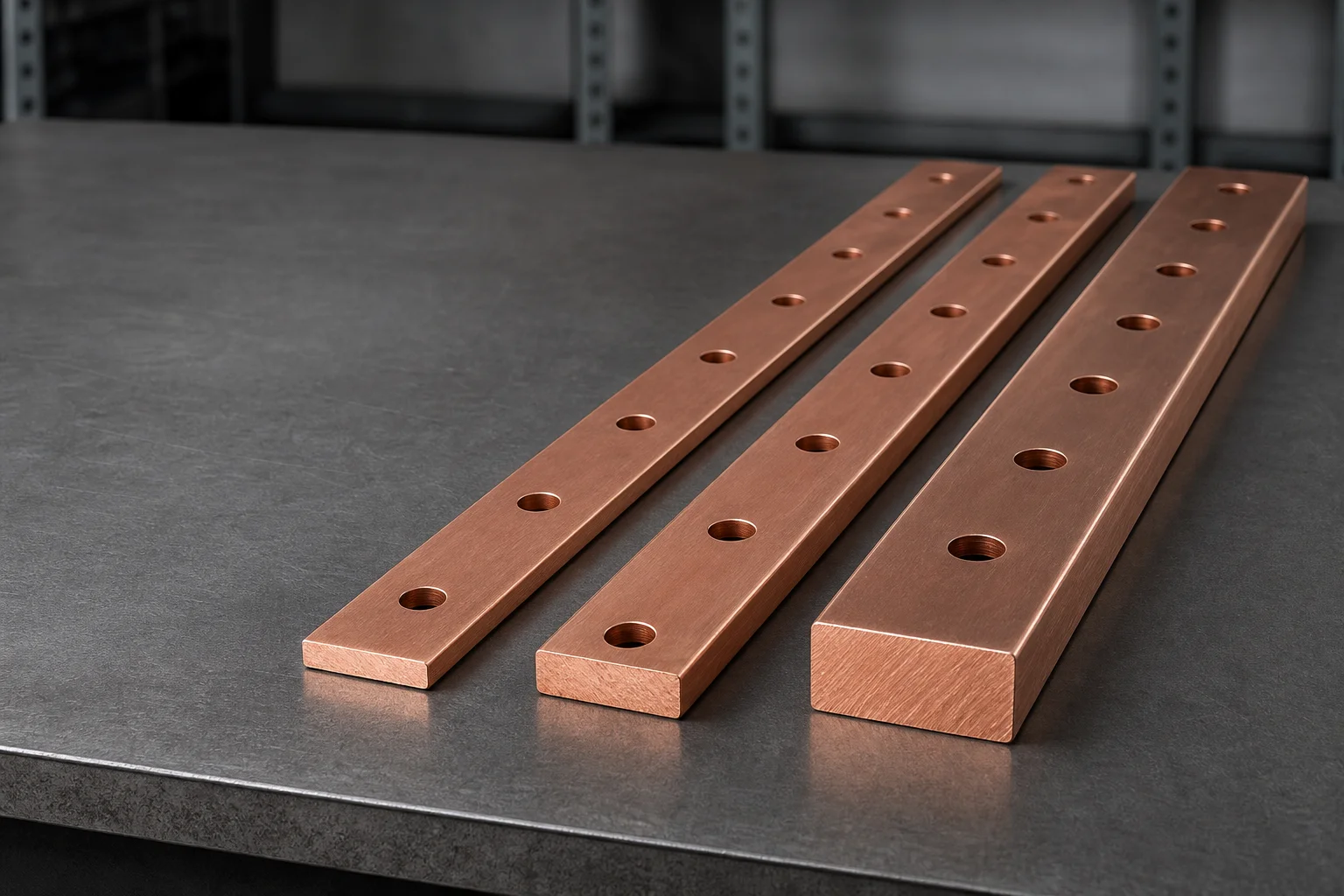
Take a copper bar 50 mm wide and 10 mm thick, one metre long, at 20 °C.
- Cross-sectional area: 50 mm × 10 mm = 500 mm² = 500 × 10⁻⁶ m²
- R = 1.724 × 10⁻⁸ × 1 / (500 × 10⁻⁶) = 3.448 × 10⁻⁵ Ω
- R ≈ 0.0345 mΩ per metre
That single number — about a thirty-fifth of a milliohm per metre — is the foundation for everything else. Notice how small it is: this is why busbars are used instead of cable for high-current connections. The equivalent cable would need a much larger conductor to match it.
Step 2 — correcting for temperature
Resistance rises as the bar heats up. Over the range that matters for busbars, the relationship is close to linear:
RT = R20 × [1 + α × (T − 20)]
Continuing the example, at a conductor temperature of 85 °C:
- Temperature difference: 85 − 20 = 65 °C
- Multiplier: 1 + 0.00393 × 65 = 1.255
- R = 0.0345 mΩ × 1.255 ≈ 0.0433 mΩ per metre
Resistance has increased by about 26 per cent. This is not a rounding error, and it is the reason a busbar's losses at working temperature are meaningfully higher than a cold measurement suggests. It is also why the temperature you size against is the conductor's working temperature, not the ambient.
Step 3 — voltage drop and power loss
With resistance known, two more numbers follow directly.
Voltage drop: V = I × R
Power loss: P = I² × R
At 800 A through that one-metre bar at 85 °C:
- Current density: 800 A / 500 mm² = 1.6 A/mm²
- Voltage drop: 800 × 0.0433 × 10⁻³ = 0.0346 V, about 35 mV
- Power loss: 800² × 0.0433 × 10⁻³ ≈ 28 W
Under 35 millivolts of drop and 28 watts of heat. For a 500 mm² bar carrying 800 amps, those are healthy numbers — and the power loss figure is exactly what feeds into the thermal question, because those 28 watts have to go somewhere.
Why the length matters more than people expect
Both drop and loss scale linearly with length. A bar run that doubles in length doubles the loss and doubles the drop, with no change in current density. On long runs it is usually far cheaper to add copper — a wider or thicker bar, or a parallel bar — than to accept the losses, because losses are paid continuously for the life of the installation.
Step 4 — current density, and why it is only a starting point
Current density is simply current divided by cross-sectional area, in A/mm². It is the quickest way to sanity-check a size, and the most commonly misused figure in busbar design, because the same material can carry very different current densities depending on how it is cooled.
A bar in free air with unobstructed faces sheds heat far better than the same bar packed into a sealed enclosure alongside other warm bars. A painted or sleeved bar radiates differently from a bare one. Ambient temperature sets how much headroom exists before the limit is reached. Because of this, a current-density figure copied from someone else's installation carries no guarantee — it was calculated against their cooling conditions, not yours.
The practical approach is to reverse the calculation. Pick a bar size, work out the loss from the resistance method above, then estimate the temperature rise and check it against the limit set by the applicable standard, the insulation rating and the enclosure. If the rise is too high, go up a size and repeat.
Estimating temperature rise
Temperature rise is a heat balance: the power dissipated in the bar must leave through its exposed surface. Approximately:
ΔT ≈ P / (h × Asurface)
where Asurface is the exposed surface area in square metres and h is a combined convection-and-radiation coefficient. For a small naturally cooled surface, h is of the order of 10 W/m²·K — but it varies with orientation, emissivity and airflow, which is why this is an approximation for checking, not a rating.
For the example bar, the exposed perimeter is 2 × (50 + 10) = 120 mm, so one metre presents about 0.12 m² of surface. With 28 W of loss:
- ΔT ≈ 28 / (10 × 0.12) ≈ 23 K
So a 23 °C rise above ambient — comfortable in a 40 °C room, and noticeably less comfortable in a sealed enclosure at 60 °C ambient. That is exactly the kind of decision the calculation is meant to inform.
Two things push this estimate off: coating and grouping. A good dip-coated or powder-coated finish raises surface emissivity and helps radiation, which is a genuine advantage of those products beyond electrical insulation. Grouping does the opposite — parallel bars heat each other, and the middle bar of a group runs hottest.
Skin effect: why DC sizing fails at high frequency
At DC, current uses the whole cross-section. At AC it crowds toward the surface, reducing the effective area. The depth at which current density falls to about 37 per cent of its surface value is the skin depth:
δ = √(ρ / (π × f × μ₀))
Evaluating this for the two materials at power frequencies gives numbers that are useful to keep in mind:
| Material | Skin depth at 50 Hz | Skin depth at 60 Hz |
|---|---|---|
| Copper | ≈ 9.3 mm | ≈ 8.5 mm |
| Aluminium | ≈ 12.0 mm | ≈ 11.0 mm |
Since most low-voltage busbars are less than 10 mm thick, the skin effect at 50 or 60 Hz is present but moderate for a single flat bar. It becomes material when bars are thick, when several thin bars are used in parallel, or when the frequency rises well above the mains — in inverters, drives and high-frequency power electronics.
Where it matters, flat is better than round: a thin wide bar has more surface per unit of area than a thick bar, which is one reason laminated busbar construction uses many thin conductors rather than one thick one.
Inductance: the loop matters, not the bar
Busbar inductance is dominated by the loop formed between the outgoing and returning conductors, not by the bar itself. A rough relationship for two parallel plates of width w separated by a distance d is:
L per metre ≈ μ₀ × d / w
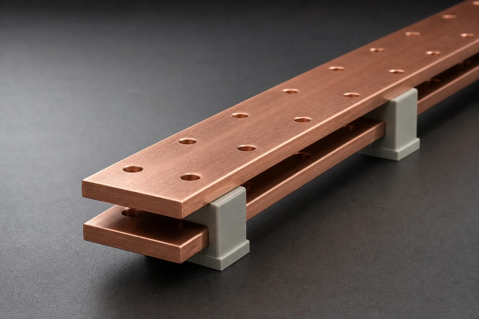
For a 50 mm wide pair separated by 10 mm, that gives about 0.25 µH per metre. The important part is the ratio d/w: halving the gap halves the inductance, while widening the bar reduces it further. This is the entire engineering reason laminated busbars exist — thin conductors with a thin insulator between them put the return path as close as physically possible to the go path, collapsing the loop area.
The practical implication is that a bar's shape can be electrically adequate and still be poor for a fast-switching circuit, and that re-arranging the same bars can change behaviour more than changing their size.
Weight: for shipping, structure and supports
Weight follows from volume and density, and it is worth calculating early because it drives support spacing, insulator loading and freight cost.
Weight = cross-sectional area × length × density
For the same 50 × 10 mm bar, one metre long:
- Volume: 500 mm² × 1000 mm = 500,000 mm³ = 500 cm³
- Copper: 500 × 8.96 = 4,480 g = 4.48 kg
- Aluminium: 500 × 2.70 = 1,350 g = 1.35 kg
The aluminium bar is about 30 per cent of the copper weight for the same volume — and even after upsizing its cross-section by roughly 1.6 times to match conductivity, it still comes out substantially lighter.
What no calculator can tell you
The arithmetic above is necessary but not sufficient. Four things sit outside it:
- Short-circuit withstand. The thermal and mechanical forces during a fault are a separate calculation against the assembly standard, and they often dictate the final size rather than the continuous rating.
- Joint performance. A correctly sized bar with a badly torqued or oxidised joint will run hotter than the bar ever will. The joint, not the bar, is usually the limiting component.
- Mechanical duty. Vibration, thermal cycling and fault forces all load the supports and the bar, and no electrical calculation covers them.
- Corrosion and environment. Humidity, salt and dissimilar metals change the joint resistance over years, which changes the temperature rise.
The honest summary is that a calculation gets you to a defensible starting size. Confirming it requires the applicable standard for your assembly plus the manufacturer's data for the actual bar, plating and joint you intend to use.
Frequently asked questions
Is there a standard busbar size calculator I can trust?
A calculator is reliable for the geometric part — resistance, voltage drop, weight — because that is pure physics and the inputs are unambiguous. Treat any ampacity or temperature-rise output as an estimate only, since it must assume cooling conditions. If the tool does not ask about ambient temperature, enclosure and grouping, treat its current figure as indicative.
Why does the same bar carry different current in different installations?
Because the limit is temperature rise, and temperature rise depends on how well the bar sheds heat. The same bar in free air, in a ventilated enclosure and in a sealed box will have three different ratings. The bar has not changed; the cooling has.
How do I convert between cross-section and current?
You cannot, directly — that is the whole point. Current capacity is set by the temperature rise, which depends on resistance, surface area and cooling. Two bars with the same cross-section but different shapes (one square, one flat and wide) have different surface areas and therefore different temperature rises at the same current.
When should I use copper and when aluminium?
Copper when space is tight or joints are numerous and small; aluminium when the run is long, the current is high, weight matters, and the joints can be properly prepared and maintained. Plated aluminium is the middle ground where joints matter but weight is still a priority.
Does plating change the calculation?
Only slightly for resistivity, since tin plating is thin and its resistivity is higher but its contribution is small. It matters much more for the joint — a plated surface resists oxidation and keeps joint resistance stable over time, which is what actually determines whether the calculated performance is still true after five years.
Sizing a busbar with confidence
Work through it in order: resistance from geometry, corrected for working temperature; voltage drop and loss from the current; then a temperature-rise check against the real cooling conditions. That sequence gives you a size you can defend, and it makes clear which assumptions are doing the work. Where the answer is marginal, the right move is to ask the manufacturer to run the calculation against your actual enclosure and ambient — a supplier who will do that for you is worth more than any calculator.
Zhejiang Zhongyan New Energy Co., Ltd. manufactures copper and aluminium busbars in custom widths, thicknesses and hole patterns, with tinned, dip-coated and insulated options, and can quote bars to your drawing with the cross-section you have calculated.
Driven by the development of new energy and aiming for "zero carbon".
Copyright © Zhejiang Zhongyan New Energy Co., Ltd. All Rights Reserved.
